Securitytronix EZII ST-EZ32 Owner's manual
- Category
- Digital Video Recorders (DVR)
- Type
- Owner's manual
This manual is also suitable for

ST-EZ32
QUICK START GUIDE
www.securitytronix.com
www.nacebrands.com

ST-EZ32 QUICK START GUIDE
1
TABLE OF CONTENTS
Chapter1 Description of Panels ...................................................................................................................... 6
1.1 Front Panel ...................................................................................................................................... 6
1.2 Rear Panel ..................................................................................................................................... 10
Chapter 2Installation and Connections ........................................................................................................ 13
2.1 NVR Installation ............................................................................................................................ 13
2.2 Hard Disk Installation .................................................................................................................... 13
2.3 Connections ................................................................................................................................... 17
Wiring of Alarm Input ...................................................................................................................... 17
Wiring of Alarm Output ................................................................................................................... 17
Using Alarm Connectors .................................................................................................................. 18
Controller Connection ...................................................................................................................... 18
2.4 HDD Storage Calculation Chart .................................................................................................... 19
Chapter 3Menu Operation ............................................................................................................................ 20
3.1 Menu Structure .............................................................................................................................. 20
3.2 Startup and Shutdown .................................................................................................................... 20
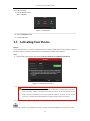
3.3 Activating Your Device ................................................................................................................. 21
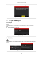
3.4 Login and Logout .......................................................................................................................... 22
User Login ....................................................................................................................................... 22
User Logout ..................................................................................................................................... 23
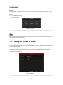
3.5 Using the Setup Wizard ................................................................................................................. 23
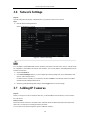
3.6 Network Settings ........................................................................................................................... 24
3.7 Adding IP Cameras ........................................................................................................................ 24
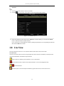
3.8 Live View ...................................................................................................................................... 25
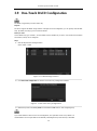
3.9 One-Touch RAID Configuration ................................................................................................... 26
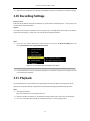
3.10 Recording Settings......................................................................................................................... 27
3.11 Playback ........................................................................................................................................ 27
Chapter 4Remote Access................................................................................................................................. 29
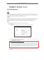
4.1 Web Browser ................................................................................................................................... 29
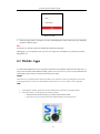
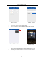
4.2 Mobile Apps .................................................................................................................................... 30

ST-EZ32 QUICK START GUIDE
2
Quick Start Guide
About this Manual
This Manual is applicable to Securitytronix EZII Network Video Recorders (NVR).
The Manual includes instructions for using and managing the product. Pictures, charts, images and all other
information hereinafter are for description and explanation only. The information contained in the Manual
is subject to change, without notice, due to firmware updates or other reasons.
Please use this user manual under the guidance of professionals to ensure a safe and proper deployment.
Legal Disclaimer
THIS HARDWARE AND SOFTWARE IS PROVIDED BY SECURITYTRONIX "AS IS'' AND ANY
EXPRESS OR IMPLIED WARRANTIES, INCLUDING, BUT NOT LIMITED TO, THE IMPLIED
WARRANTIES OF MERCHANTABILITY AND FITNESS FOR A PARTICULAR PURPOSE ARE
DISCLAIMED. IN NO EVENT SHALL SECURITYTRONIX S BE LIABLE FOR ANY DIRECT, INDIRECT,
INCIDENTAL, SPECIAL, EXEMPLARY, OR CONSEQUENTIAL DAMAGES (INCLUDING, BUT NOT
LIMITED TO, PROCUREMENT OF SUBSTITUTE GOODS OR SERVICES; LOSS OF USE, DATA, OR
PROFITS; OR BUSINESS INTERRUPTION) HOWEVER CAUSED AND ON ANY THEORY OF
LIABILITY, WHETHER IN CONTRACT, STRICT LIABILITY, OR TORT (INCLUDING NEGLIGENCE OR
OTHERWISE) ARISING IN ANY WAY OUT OF THE USE OF THIS HARDWARE AND SOFTWARE,
EVEN IF ADVISED OF THE POSSIBILITY OF SUCH DAMAGE.
THE USE OF THE PRODUCT SHALL BE WHOLLY AT YOUR OWN RISK. SECURITYTRONIX SHALL
NOT BE LIABLE FOR ANY ABNORMAL OPERATION, BREACH OF PRIVACY OR OTHER DAMAGES
RESULTING FROM CYBER ATTACK, HACKER ATTACK, VIRUS INFECTION, OR OTHER INTERNET
SECURITY RISKS. SURVEILLANCE LAWS VARY BY JURISDICTION. PLEASE CHECK ALL
RELEVANT LAWS IN YOUR JURISDICTION BEFORE USING THIS PRODUCT IN ORDER TO ENSURE
THAT USE CONFORMS TO ALL APPLICABLE LAWS. SECURITYTRONIX SHALL NOT BE LIABLE IN
THE EVENT THAT THIS PRODUCT IS USED WITH ILLEGITIMATE PURPOSES.
For further assistance, or if you encounter any issue while using this product, please contact
your distributor or Securitytronix at: 800-688-9282 Press 3 for support, then 2 for CCTV.

3
Regulatory Information
FCC Information
FCC compliance: This equipment has been tested and found to comply with the limits for a Class A digital device,
pursuant to part 15 of the FCC Rules. These limits are designed to provide reasonable protection against harmful
interference when the equipment is operated in a commercial environment. This equipment generates, uses, and
can radiate radio frequency energy and, if not installed and used in accordance with the instruction manual, may
cause harmful interference to radio communications. Operation of this equipment in a residential area is likely to
cause harmful interference in which case the user will be required to correct the interference at his own expense.
FCC Conditions
This device complies with part 15 of the FCC Rules. Operation is subject to the following two conditions:
1. This device may not cause harmful interference.
2. This device must accept any interference received, including interference that may cause undesired operation.
EU Conformity Statement
This product and - if applicable - the supplied accessories too are marked with "CE" and comply
therefore with the applicable harmonized European standards listed under the EMC Directive
2004/108/EC, the RoHS Directive 2011/65/EU.
2012/19/EU (WEEE directive): Products marked with this symbol cannot be disposed of as unsorted
municipal waste in the European Union. For proper recycling, return this product to your local
supplier upon the purchase of equivalent new equipment, or dispose of it at designated collection
points. For more information see: www.recyclethis.info
2006/66/EC (battery directive): This product contains a battery that cannot be disposed of as unsorted
municipal waste in the European Union. See the product documentation for specific battery
information. The battery is marked with this symbol, which may include lettering to indicate
cadmium (Cd), lead (Pb), or mercury (Hg). For proper recycling, return the battery to your supplier or to a
designated collection point. For more information see: www.recyclethis.info
Industry Canada ICES-003 Compliance
This device meets the CAN ICES-3 (A)/NMB-3(A) standards requirements.
ST-EZ32 QUICK START GUIDE

4
Safety Instruction
These instructions are intended to ensure that user can use the product correctly to avoid danger or property loss.
The precaution measure is divided into “Warnings” and “Cautions”
Warnings: Serious injury or death may occur if any of the warnings are neglected.
Cautions: Injury or equipment damage may occur if any of the cautions are neglected.
Warnings
Proper configuration of all passwords and other security settings is the responsibility of the installer and/
or
end-user.
While using this product, you must be in strict compliance with the electrical safety regulations of the
nation and region. Please refer to technical specifications for detailed information.
Input voltage should meet both the SELV (Safety Extra Low Voltage) and the Limited Power Source
with 100~240 VAC or 12 VDC according to the IEC60950-1 standard. Please refer to technical
specifications for detailed information.
Do not connect several devices to one power adapter as adapter overload may cause over-heating or a
fire hazard.
Please make sure that the plug is firmly connected to the power socket.
If smoke, odor or noise rise from the device, turn off the power at once and unplug the power cable, and
then please contact technical support.
Preventive and Cautionary Tips
Before connecting and operating your device, please be advised of the following tips:
Ensure the unit is installed in a well-ventilated, dust-free environment.
Unit is designed for indoor use only.
Keep all liquids away from the device.
Ensure environmental conditions meet factory specifications.
Ensure unit is properly secured to a rack or shelf. Major shocks or jolts to the unit as a result of dropping
it may cause damage to the sensitive electronics within the unit.
Use the device in conjunction with a UPS if possible.
Power down the unit before connecting and disconnecting accessories and peripherals.
Surveillance grade HDDs should be used with this recorder.
Improper use or replacement of the battery may result fire or explosion hazard. Replace with the same or
equivalent type only. Dispose of used batteries according to the instructions provided by the battery
manufacturer.
Warnings Follow these
safeguards to prevent serious
injury or death.
Cautions Follow these precautions
to prevent potential injury or
material damage.
ST-EZ32 QUICK START GUIDE

5
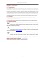
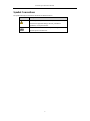
Symbol Conventions
The symbols that may be found in this document are defined as follows.
Symbol
Description
Indicates a potentially hazardous situation, which if not avoided,
could result in equipment damage, data loss, performance
degradation, or unexpected results.
Provides additional information to emphasize or supplement
important points of the main text.
ST-EZ32 QUICK START GUIDE

6
Chapter1 Description of Panels
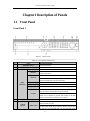
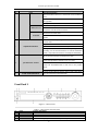
1.1 Front Panel
Front Panel 1
Figure 1. 1 Front Panel
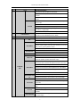
Table 1. 1 Description of Interfaces
No.
Name
Function Description
1
POWER ON/OFF
Power on/off switch.
2
IR Receiver
Receiver for IR remote
3
Status
Indicators
ALARM
Turns red when a sensor alarm is detected.
READY
Ready LED is normally blue, indicating that the device is
functioning properly.
STATUS
Turns blue when device is controlled by an IR remote.
Turns red when controlled by a keyboard and purple when IR
remote and keyboard is used at the same time.
HDD
Flashes red when data is being read from or written to HDD.
MODEM
Reserved for future usage.
TX/RX
Flashes blue when network connection is functioning properly.
GUARD
Guard LED turns blue when the device is in armed status; at this
time, an alarm is enabled when an event is detected.
The LED turns off when the device is unarmed. The arm/disarm
status can be changed by pressing and holding on the ESC
button for more than 3 seconds in live view mode.
4
DVD-R/W
Slot for DVD-R/W.
5
Control
Buttons
DIRECTION
The DIRECTION buttons are used to navigate between different
fields and items in menus.
In the Playback mode, the Up and Down button is used to speed
up and slow down recorded video. The Left and Right button
ST-EZ32 QUICK START GUIDE

7
No.
Name
Function Description
will select the next and previous record files.
In Live View mode, these buttons can be used to cycle through
channels.
In PTZ control mode, it can control the movement of the PTZ
camera.
ENTER
The ENTER button is used to confirm selection in any of the
menu modes.
It can also be used to tick checkbox fields.
In Playback mode, it can be used to play or pause the video.
In single-frame Playback mode, pressing the button will advance
the video by a single frame.
In Auto-switch mode, it can be used to stop /start auto switch.
6
USB Interfaces
Universal Serial Bus (USB) ports for additional devices such as
USB mouse and USB Hard Disk Drive (HDD).
7
Front Panel Lock
You can lock or unlock the panel by the key.
8
Composite
Keys
ESC
Back to the previous menu.
Press for Arming/disarming the device in Live View mode.
REC/SHOT
Enter the Manual Record setting menu.
In PTZ control settings, press the button and then you can call a
PTZ preset by pressing Numeric button.
It is also used to turn audio on/off in the Playback mode.
PLAY/AUTO
The button is used to enter the Playback mode.
It is also used to auto scan in the PTZ Control menu.
ZOOM+
Zoom in the PTZ camera in the PTZ Control setting.
A/FOCUS+
Adjust focus in the PTZ Control menu.
It is also used to switch between input methods (upper and
lowercase alphabet, symbols and numeric input).
EDIT/IRIS+
Edit text fields. When editing text fields, it will also function as
a Backspace button to delete the character in front of the cursor.
On checkbox fields, pressing the button will tick the checkbox.
In PTZ Control mode, the button adjusts the iris of the camera.
In Playback mode, it can be used to generate video clips for
backup.
Enter/exit the folder of USB device and eSATA HDD.
MAIN/SPOT/ZOO
M-
Switch between main and spot output.
In PTZ Control mode, it can be used to zoom out the image.
F1/ LIGHT
Select all items on the list when used in a list field.
In PTZ Control mode, it will turn on/off PTZ light (if
applicable).
In Playback mode, it is used to switch between play and reverse
play.
F2/ AUX
Cycle through tab pages.
In synchronous playback mode, it is used to switch between
channels.
MENU/WIPER
Press the button will help you return to the Main menu (after
successful login).
ST-EZ32 QUICK START GUIDE

8
No.
Name
Function Description
Press and hold the button for 5 seconds will turn off audible key
beep.
In PTZ Control mode, the MENU/WIPER button will start wiper
(if applicable).
In Playback mode, it is used to show/hide the control interface.
PREV/FOCUS-
Switch between single screen and multi-screen mode.
In PTZ Control mode, it is used to adjust the focus in
conjunction with the A/FOCUS+ button.
PTZ/IRIS-
Enter the PTZ Control mode.
In the PTZ Control mode, it is used to adjust the iris of the PTZ
camera.
9
Alphanumeric Buttons
Switch to the corresponding channel in Live view or PTZ
Control mode.
Input numbers and characters in Edit mode.
Switch between different channels in Playback mode.
The light of the button is blue when the corresponding channel is
recording; it is red when the channel is in network transmission
status; it is pink when the channel is recording and transmitting.
10
JOG SHUTTLE Control
Moves the active selection up and down in a menu.
Cycles through different channels in live view mode.
Jumps 30s forward/backward in video files in the playback
mode.
Controls the movement of the PTZ camera in PTZ control mode
11
SLOW DOWN/SPEED UP
Slow down/speed up in playback mode.
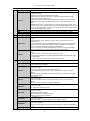
Front Panel 2
Figure 1. 2 Front Panel
Table 1. 2 Description of Front Panel
No.
Name
Function Description
1
POWER ON/OFF
Power on/off switch.
2
USB Interface
Connect to USB mouse or USB flash memory.
3
IR Receiver
Receiver for IR remote control. devices.
4
POWER
Power indicator lights green when the DVR is powered up.
ST-EZ32 QUICK START GUIDE

9
READY
Ready indicator is normally green, indicating that the DVR is functioning properly.
STATUS
Indicator turns green when DVR is controlled by an IR remote control with the
address from 1~254;
Indicator turns red when the SHIFT button is used;
Indicator does not light when the DVR is controlled by a keyboard or by the IR
remote control with the address of 255;
Indicator turns green when the DVR is controlled by IR remote control (with the
address from 1~254) and keyboard at the same time , and the SHIFT button is not
used;
Indicator turns orange : (a) when the DVR is controlled by IR remote control (with
the address from 1~254) and keyboard at the same time and the SHIFT button is used
as well; (b) when the DVR is controlled by IR remote control (with the address from
1~254) and the SHIFT button is used.
ALARM
Alarm indicator turns red when a sensor alarm is detected.
HDD
HDD indicator blinks red when data is being read from or written to the HDD.
Tx/Rx
TX/RX indictor blinks in green when network connection is functioning properly.
5
DVD-ROM
Slot for DVD-ROM.
6
DIRECTION
The DIRECTION buttons are used to navigate between different fields and items in
menus.
In Playback mode, the Up and Down button is used to speed up and slow down
recorded video.
In All-day Playback mode, the Left/Right button can be used to select the recorded
video of next/previous day; in Playback by Normal Video Search, the Left/Right
button can be used to select the next/previous recorded file.
In Live View mode, the directional buttons can be used to cycle through channels.
In PTZ control mode, it can control the movement of the PTZ camera.
ENTER
Confirm selection in any of the menu modes. It can also be used to tick checkbox
fields.
In Playback mode, it can be used to play or pause the video.
In Single-frame Playback mode, pressing the ENTER button will advance the video
by a single frame.
In Auto-switch mode, it can be used to stop /start auto switch.
7
SHIFT
Switch of compound keys between the numeric/letter input and functional control.
1/MENU
Enter numeral “1”;
Access the main menu interface.
2ABC/F1
Enter numeral “2”;
Enter letters “ABC”;
The F1 button can be used to select all items on the list;
In PTZ Control mode, the F1 button can be used to zoom out (zoom-) the PTZ
camera;
In live view or playback mode, the F1 button can be used to switch between main
and spot video output.
3DEF/F2
Enter numeral “3”;
Enter letters “DEF”;
In PTZ Control mode, the F1 button can be used to zoom in (zoom+) the PTZ
camera;
The F2 button can be used to cycle through tab pages.
4GHI/ESC
Enter numeral “4”;
Enter letters “GHI”;
Exit and back to the previous menu.
5JKL/EDIT
Enter numeral “5”;
Enter letters “JKL”;
Delete characters before cursor;
Select the checkbox and ON/OFF switch;
Start/stop record clipping in playback.
6MNO/PLAY
Enter numeral “6”;
Enter letters “MNO”;
In Playback mode, it is used for direct access to playback interface.
7PQRS/REC
Enter numeral “7”;
Enter letters “PQRS”;
Manual record, for direct access to manual record interface; manually enable/disable
record.
8TUV/PTZ
Enter numeral “8”;
ST-EZ32 QUICK START GUIDE

10
Enter letters “TUV”;
Access PTZ control interface.
9WXYZ/PREV
Enter numeral “9”;
Enter letters “WXYZ”;
Multi-camera display in live view;
In Playback mode or MenuPlaybackTag playback interface, this button can be
used to delete the selected tag.
0/A
Enter numeral “0”;
Switch between input methods (upper and lowercase alphabet, symbols and numeric
input).
In Playback mode, this button can be used to add the default tag.
8
JOG SHUTTLE
Control
Move the active selection in a menu. The inner ring will move the selection up and
down; the outer ring will move it left and right.
In Playback mode, the inner ring is used to jump 30s forward/backward in video
files. The outer ring can be used to speed up/slow down the video.
In Live View mode, it can be used to cycle through different channels.
In PTZ control mode, in can control the movement of the PTZ camera.
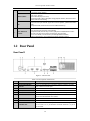
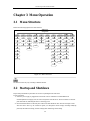
1.2 Rear Panel
Rear Panel 1
Figure 1. 3 Rear Panel
Table 1. 3 Description of Interfaces
No.
Item
Description
1
LAN1/LAN2 Interface
2 RJ-45 10/100/1000 Mbps self-adaptive Ethernet interfaces provided.
2
LINE IN
RCA connector for audio input.
3
AUDIO OUT
2 RCA connectors for audio output.
4
HDMI1/HDMI2
HDMI video output connector.
5
VGA1/VGA2
DB9 connector for VGA output. Display local video output and menu.
6
USB 3.0 interface
Universal Serial Bus (USB) ports for additional devices such as USB
mouse and USB Hard Disk Drive (HDD).
7
RS-232 Interface
Connector for RS-232 devices.
8
eSATA
Connects external SATA HDD, CD/DVD-RM.
9
Controller Port
D+, D- pin connects to Ta, Tb pin of controller. For cascading devices,
the first NVR’s D+, D- pin should be connected with the D+, D- pin of
the next NVR.
ST-EZ32 QUICK START GUIDE

11
No.
Item
Description
ALARM IN
Connector for alarm input.
ALARM OUT
Connector for alarm output.
10
AC 100V ~ 240V
100 to 240 VAC power supply.
11
Power Switch
Switch for turning on/off the device.
12
GROUND
Ground (needs to be connected when NVR starts up).
ST-EZ32 QUICK START GUIDE

12
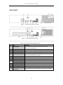
Rear Panel 2
Figure 1. 4 Without POE Interface Series
Figure 1. 5 With POE Interface Series
Table 1. 4 Description of Rear Panel Interfaces
No.
Item
Description
1
LAN Interface
1 network interface provided for POE Series and 2 network
interfaces for non POE series.
2
AUDIO OUT
RCA connector for audio output.
3
LINE IN
RCA connector for audio input.
4
HDMI
HDMI video output connector.
5
USB 3.0 interface
Universal Serial Bus (USB) ports for additional devices such as USB
mouse and USB Hard Disk Drive (HDD).
6
RS-232 Interface
Connector for RS-232 devices.
7
VGA
DB9 connector for VGA output. Display local video output and menu.
8
RS-485 Interface
Half-duplex connector for RS-485 devices.
9
ALARM IN
Connector for alarm input.
ALARM OUT
Connector for alarm output.
10
GROUND
Ground (needs to be connected when NVR starts up).
11
AC 100V ~ 240V
100V ~ 240VAC power supply.
12
Power Switch
Switch for turning on/off the device.
13
Network Interfaces with
PoE function
Network interfaces for the cameras and to provide power over Ethernet.
ST-EZ32 QUICK START GUIDE

13
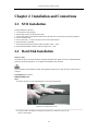
Chapter 2 Installation and Connections
2.1 NVR Installation
During installation of the NVR:
1. Use brackets for rack mounting.
2. Ensure ample room for audio and video cables.
3. When routing cables, ensure that the bend radius of the cables are no less than five times than its diameter.
4. Connect the alarm cable.
5. Allow at least 2cm (≈0.75-inch) of space between rack mounted devices.
6. Ensure the NVR is grounded.
7. Environmental temperature should be within the range of 14ºF ~ 131ºF.
8. Environmental humidity should be within the range of 10% ~ 90%.
2.2 Hard Disk Installation
Before you start:
Disconnect the power from the NVR before installing a hard disk drive (HDD). A factory recommended HDD
should be used for this installation. Up to eight SATA hard disks can be installed.
As the installation steps of HDD are similar among different models, here we take the steps of certain series as
examples.
Tools Required: Screwdriver.
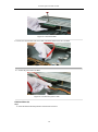
HDD Installation (A)
Steps:
1. Remove the NVR cover by unfastening the screws on the back and side.
Figure 2. 1 Remove the Cover
2. Install the HDD in the HDD rack using the provided screws. Fasten the screws on the
button to fix the HDD.
ST-EZ32 QUICK START GUIDE

14
Figure 2. 2 Install the HDD
3. Connect one end of the data cable to the NVR motherboard and the other end to the HDD.
Figure 2. 3 Connect the data cable
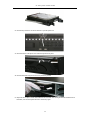
4. Connect the power cable to the HDD.
Figure 2. 4 Connect the power cable
HDD Installation (B)
Steps:
1. Fasten the hard disk mounting handle to the hard disk with screws.
ST-EZ32 QUICK START GUIDE

15
2. Insert the key and turn in clockwise direction to open the panel lock.
3. Press the buttons on the panel of two sides and open the front panel.
4. Insert the hard disk along the slot until it is placed into position.
5. Repeat the above steps to install other hard disks onto the NVR. After having finished the installation of all
hard disks, close the front panel and lock it with the key again.
ST-EZ32 QUICK START GUIDE

16
ST-EZ32 QUICK START GUIDE

17
2.3 Connections
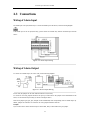
Wiring of Alarm Input
The alarm input is an open/closed relay. To connect the alarm input to the device, use the following diagram.
If the alarm input is not an open/close relay, please connect an external relay between the alarm input and the
device.
Figure 2. 5 Alarm Input Wiring
Wiring of Alarm Output
To connect to an alarm output (AC or DC load), use the following diagram:
Figure 2. 6 Alarm Output Wiring
For DC load, the jumpers can be used within the limit of 12V/1A safely.
To connect an AC load, jumpers should be left open (you must remove the jumper on the motherboard in the
NVR). Use an external relay for safety (as shown in the figure above).
There are 4 jumpers (JP1, JP2, JP3, and JP4) on the motherboard, each corresponding with one alarm output. By
default, jumpers are connected. To connect an AC load, jumpers should be removed.
Example:
If you connect an AC load to the alarm output 3 of the NVR, then you must remove the JP 3 jumper.
ST-EZ32 QUICK START GUIDE

18
Using Alarm Connectors
To connect alarm devices to the NVR:
1. Disconnect the pluggable block from the ALARM IN /ALARM OUT terminal block.
2. Unfasten stop screws from the pluggable block, insert signal cables into slots and fasten stop screws. Ensure
signal cables are tight.
3. Connect the pluggable block back into terminal block.
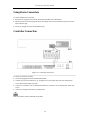
Controller Connection
Figure 2. 7 Controller Connection
To connect a controller to the NVR:
1. Disconnect pluggable block from the KB terminal block.
2. Unfasten stop screws from the KB D+, D- pluggable block, insert signal cables into slots and fasten stop
screws. Ensure signal cables are in tight.
3. Connect Ta on controller to D+ on terminal block and Tb on controller to D- on terminal block. Fasten stop
screws.
4. Connect the pluggable block back into terminal block.
Make sure both the controller and NVR are grounded.
ST-EZ32 QUICK START GUIDE

19
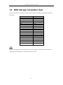
2.4 HDD Storage Calculation Chart
The following chart shows an estimation of storage space used based on recording at one channel for an hour at a
fixed bit rate.
Bit Rate
Storage Used
96K
42M
128K
56M
160K
70M
192K
84M
224K
98M
256K
112M
320K
140M
384K
168M
448K
196M
512K
225M
640K
281M
768K
337M
896K
393M
1024K
450M
1280K
562M
1536K
675M
1792K
787M
2048K
900M
4096K
1.8G
8192K
3.6G
16384K
7.2G
Please note that supplied values for storage space used is just for reference. The storage values in the chart are
estimated by formulas and may have some deviation from actual value.
ST-EZ32 QUICK START GUIDE
Page is loading ...
Page is loading ...
Page is loading ...
Page is loading ...
Page is loading ...
Page is loading ...
Page is loading ...
Page is loading ...
Page is loading ...
Page is loading ...
Page is loading ...
Page is loading ...
Page is loading ...
-
 1
1
-
 2
2
-
 3
3
-
 4
4
-
 5
5
-
 6
6
-
 7
7
-
 8
8
-
 9
9
-
 10
10
-
 11
11
-
 12
12
-
 13
13
-
 14
14
-
 15
15
-
 16
16
-
 17
17
-
 18
18
-
 19
19
-
 20
20
-
 21
21
-
 22
22
-
 23
23
-
 24
24
-
 25
25
-
 26
26
-
 27
27
-
 28
28
-
 29
29
-
 30
30
-
 31
31
-
 32
32
-
 33
33


Securitytronix EZII ST-EZ32 Owner's manual
- Category
- Digital Video Recorders (DVR)
- Type
- Owner's manual
- This manual is also suitable for
Ask a question and I''ll find the answer in the document
Finding information in a document is now easier with AI
Other documents
-
Northern TVIDVR4 Quick Manual
-
 Vezco VZ-NVR-12M256-24HD Quick start guide
-
Northern NVR4POE Quick Manual
-
 LT Security LTN8608-P8N Quick start guide
-
WorldEyeCam 3108 User guide
-
WorldEyeCam NVR6000-16 User guide
-
Security Tronix ST-NVR-128 Owner's manual
-
 Hunt CCTV HAR503-24 User manual
-
Hills NVR-CH16 User manual
-
Tyco ADEMD4B000TV User manual


