Hitachi CS 27EPA(S) User manual
- Category
- Power chainsaws
- Type
- User manual
This manual is also suitable for

PRODUCT NAME
Hitachi Engine Pole Saw
Models CS 27EPAP(S)
CS 27EPA(S)
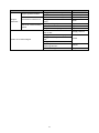
TROUBLESHOOTING GUIDE ---------------------------------------------------------------------------------------------- 1
1. Troubleshooting and correction ------------------------------------------------------------------------------- 1
REPAIR GUIDE ----------------------------------------------------------------------------------------------------------------- 3
1. Precaution on maintenance, inspection and repair ------------------------------------------------------ 3
2. Inspection criteria for each section and consumable parts -------------------------------------------- 3
CONTENTS
Page
LIST Nos.
CS 27EPAP: F021
CS 27EPA: F020
Sep. 2012
International Sales Division
䠟

-1-
1. Troubleshooting and correction
Problem Cause Corrective action
Starter grip
cannot be
pulled.
Crank shaft does not turn.
Seized piston ring
Disassemble and
replace.
Seized connecting rod bearing
Seized piston and cylinder
Worn piston or cylinder
Crank shaft turns. Defective starter body ass'y
Engine
does not
start.
Dry spark plug
Empty fuel tank Replenish with fuel.
Clogged pump filter body comp. Clean or replace.
Folded or improperly connected or
damaged shield tube ass'y
Check or replace.
Defective air vent valve of tank cap
ass’y
Replace.
Clogged carburetor ass’y Clean.
Defective carburetor ass’y Check or replace.
No spark
Stained or defective spark plug Clean or replace.
Improperly connected high tension
cable and terminal
Check.
Damaged high tension cable Replace.
Improper air gap Adjust.
Defective ignition coil ass'y Replace.
Defective stop switch Replace.
Improperly connected or damaged
internal wires
Check or replace.
No compression
Defective piston ring
Replace.
Defective oil seals of crank case ass'y
Engine
starts but
cannot
continue
idling.
Weak sparking
Stained or defective spark plug Clean or replace.
Improper air gap Adjust.
Defective ignition coil ass'y Replace.
Weak compression
Defective piston ring
Replace. Defective oil seals of crank case ass'y
Worn piston or cylinder
Improper fuel-air mixture
Clogged carburetor ass’y Clean.
Defective carburetor ass’y Check or replace.
Clogged pump filter body comp. Clean or replace.
Folded or improperly connected or
damaged shield tube ass'y
Check or replace.
Too low idling speed Adjust.
Engine
starts and
accelerates
but ...
Engine stops.
Clogged carburetor ass’y Clean.
Defective carburetor ass’y Check or replace.
Clogged pump filter body comp. Clean or replace.
Accelerates improperly.
(Engine does not rev up.)
Defective carburetor ass’y Check or replace.
Clogged cleaner element of cleaner
ass’y
Clean.
Muffler clogged with carbon Clean.
Exhaust port of cylinder clogged with
carbon
Clean.
Faulty ignition coil ass’y Replace
Degraded fuel Replace
TROUBLESHOOTING GUIDE

-2-
Problem Cause Corrective action
Engine
starts but ...
Engine speed fluctuates.
Clogged carburetor ass’y Clean.
Defective carburetor ass’y Check or replace.
Consumes excessive fuel.
Defective carburetor ass’y Check or replace.
Clogged cleaner element of cleaner
ass’y
Clean.
Saw chain rotates at idling
speed.
Improper idling adjustment Adjust.
Worn clutch section Replace.
Degraded clutch spring Replace.
Chain oil is not discharged.
Insufficient amount of chain oil in
the oil tank
Supply chain oil.
Clogged chain oil discharge port
Clean.
Clogged oil filler port on the chain
bar
Clogged oil filter
Poor adjustment of chain oil
discharge amount
Adjust.
Crack of fuel pipes Replace.

-3-
This section describes troubleshooting and repair procedures for common phenomena that may occur
during pole saw operation. The procedures described here and in the “TROUBLESHOOTING GUIDE”
should be studied and referenced as needed to ensure efficient diagnosis and prompt repair of problems.
1. Precautions on maintenance, inspection and repair
• As the fuel used in the pole saw is highly flammable, carefully keep sources of fire out of the area.
Start the engine as described below, and when confirming operation, be sure to use mixed fuel of
gasoline and two-cycle oil at a ratio of 25 to 50 : 1).
• When the engine section is disassembled, always be sure to replace gaskets and oil seals with new
ones at reassembly.
• Before starting disassembly and repair, thoroughly drain all fuel from the unit into a suitable container.
• Always ensure that the engine has fully cooled down before attempting disassembly.
• When starting, operating or performing maintenance on the unit, always avoid touching hot portions of
the muffler and other hot components, high tension cable and spark plug; otherwise, you run the risk of a
serious burn injury or electric shock.
• Before starting the engine with the saw chain and the chain bar attached, make sure that there are no
other people nearby.
• Ensure proper ventilation when performing repair indoors or in other protected areas.
• Upon completion of repair, carefully confirm that all screws, nuts and bolts are properly tightened, the
throttle trigger returns properly to the idling position when released, and the engine stops when you set
the stop switch to the STOP position.
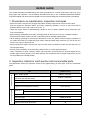
2. Inspection criteria for each section and consumable parts
The table below shows the inspection criteria to be applied during or after repair, and the consumable
parts.
Item Standard value
Inspection criteria
Idling rotation speed 2,800 to 3,200 min
-1
No-road max. rotation speed (after warming up)
[with chain bar and saw chain]
9,000 to 13,000 min
-1
Clutch engagement 3,900 to 4,700 min
-1
Engine acceleration Smooth acceleration
Clearance between external circumference of
magneto rotor and ignition coil ass'y
0.3 to 0.4 mm
Consumable parts
Spark plug
Europe, Russia, China, and Australia NGK BMR7A
Other regions CHAMPION CJ6
Gap between electrodes of the spark plug 0.6 to 0.7 mm
Saw chain type OREGON 90SG
Saw chain pitch x gauge 9.53 mm (3/8 in.) x 1.09 mm (0.043 in.)
Number of saw chain drive links 40
REPAIR GUIDE

-4-
Refer to
page
Seized piston ring
Disassemble and
replace.
12, 13
Seized connecting rod
bearing
Disassemble and
replace.
12, 13
Seized piston and cylinder
Disassemble and
replace.
12, 13
Defective starter body ass'y
Disassemble and
replace.
11, 12
Empty fuel tank Replenish with fuel. ʊ
Clogged pump filter body
comp.
Clean or replace. 9
Folded, improperly connected
or damaged shield tube ass'y
Inspect or replace. 9
Defective air vent valve of
tank cap ass’y
Replace. 9
Clogged carburetor ass’y Clean. 10
Defective carburetor ass’y Inspect or replace. 10
Stained or defective spark
plug
Clean or replace. 7
Improperly connected high
tension cable and terminal
Inspect. 8, 9
Damaged high tension cable Replace. 8, 9
Improper air gap Adjust. 8
Defective ignition coil ass'y Replace. 8
Defective stop switch Replace. 8, 9
Improperly connected or
damaged internal wires
Inspect or replace. 8, 9
Defective piston ring Clean or replace. 12, 13
Worn piston Replace. 12, 13
Defective oil seals of crank
case ass'y
Replace. 12, 13
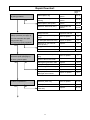
Pull the starter handle to perform
startup operation (see page 7),
and check whether the spark
plug is wet or dry.
Is fuel being properly supplied?
Yes
Remove the spark plug and
check the spark (see page 7).
Is there a
p
ro
p
er s
p
ark?
Is there compression?
Yes
No
Yes
No
No
Pull the starter handle.
Is pulling possible?
Yes
No
Repair flowchart

-5-
Is fuel consumption excessive?
Does the saw chain rotate at idling?
Yes
No
Yes
No
Refer to
page
Weak spark
Stained or defective
spark plug
Clean or
replace.
7
Improper air gap Adjust. 8
Defective ignition coil
ass'y
Replace. 8
Weak
compression
Defective piston ring Replace. 12, 13
Defective oil seals of
crank case ass'y
Replace. 12, 13
Improper
fuel-air mixture
Clogged carburetor
ass'y
Clean. 10
Defective
carburetor ass'y
Clean or
replace.
10
Clogged pump filter
body comp.
Clean or
replace.
9
Folded, improperly
connected or damaged
shield tube ass'y
Inspect or
replace.
9
Too low idling speed Adjust. 10
Improper
fuel-air mixture
Clogged carburetor
ass'y
Clean. 10
Defective carburetor
ass'y
Inspect or
replace.
10
Clogged pump filter
body comp.
Clean. 9
Improper
fuel-air mixture
Defective carburetor
ass'y
Inspect or
replace.
10
Clogged cleaner
element of cleaner
ass'y
Clean. 9
Carbon clogged in muffler, cylinder or
Exhaust vents
Clean. 9
Faulty ignition coil ass’y Replace. 8
Degraded fuel Replace. ʊ
Clogged carburetor ass'y Clean. 10
Defective carburetor ass'y
Inspect or
replace.
10
Defective carburetor ass'y
Inspect or
replace.
10
Clogged cleaner element of cleaner ass'y Clean. 9
Idling adjustment of carburetor too high Readjust. 10
Worn clutch section Replace. 11, 12
Degraded clutch spring Replace. 11, 12
Does engine stop by opening the
choke lever? Does engine stop by
accelerating? Does the engine
speed fluctuate at high speed?
Engine starts.
Does combustion continue?
Does engine accelerate by
triggering the throttle trigger?
Does the engine speed fluctuate?
No
Yes
Yes
No
Yes
No
Yes
No

-6-
Refer to
page
Insufficient amount of chain oil in the
oil tank
Supply oil. ʊ
Clogged chain oil discharge port Clean. 15, 16, 17
Clogged chain bar oil feed port Clean. 15, 16, 17
Clogged oil filter Clean. 15, 16, 17
Poorly adjusted discharge amount of
chain oil
Adjust. 15, 16, 17
Crack of fuel pipes Replace. 15, 16, 17
Is chain oil discharged?
No

-7-
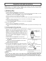
Ignited sparks
Plu
g
ca
p
Spark Plug [12]<12>
High tension cable
Metallic portion of the engine
(Avoid the area near the spark plug mounting
hole on the cylinder.)
* Wearing thick cotton gloves is recommended.
Electrode
Gap between
electrodes
(0.6 to 0.7 mm)
Spark Plug [12]<12>
[Bold] numbers in the descriptions below correspond to item numbers in the Parts List and exploded
assembly diagram for the Model CS 27EPAP; <Bold> numbers correspond to those in the Parts List and
exploded assembly diagram for the Model CS 27EPA.
1. Starting the engine
(1) When the engine is cold:
(a) Set the Stop Switch [106]<106> to the ON position.
(b) Push the Priming Body [29]<29> several times so that fuel flows through the Fuel Pipe 3 x 5 x 85
[138]<138>, Carburetor Ass'y [48]<48>, and Return Grommet [141]<141>.
(c) Set the choke lever to the CLOSED position (
).
(d) Pull the recoil starter briskly taking care to keep the handle in your grasp and not allowing it to snap
back.
(e) When you hear the engine start, return the choke lever to the RUN position (
).
(f) Pull the recoil starter briskly again.
* The marks “
”
and “
”
are indicated on the Air Cleaner Cap [53]<52>.
(2) When the engine is warm:
(a) Set the Stop Switch [106]<106> to the ON position.
(b) Pull the recoil starter briskly taking care to keep the handle in your grasp and not allowing it to snap
back.
2. Checking sparks of the spark plug
(1) Remove the Spark Plug [12]<12> from the Cylinder Set PN
[19]<19>. Use a wire brush to thoroughly clean off carbon
deposits on the Spark Plug [12]<12> electrodes. If the gap
between the electrodes is improper, readjust it (see the
illustration) and if the electrodes are wet with fuel, use a
clean, soft cloth to thoroughly wipe the fuel off. Remove fuel
left in the Cylinder Set PN [19]<19> by following the
procedure below.
(a) Set the Stop Switch [106]<106> to the ON position.
(b) Hold the Spark Plug [12]<12> away from the Cylinder Set
PN [19]<19>.
(c) Position the Cylinder Set PN [19]<19> so that its spark
plug mounting hole faces down.
(d) Pull the starter grip a few times.
(2) Insert the Spark Plug [12]<12> into the plug cap and place
the electrodes of the Spark Plug [12]<12> in contact with
the metallic portion of the engine (but avoid the area near
the Spark Plug [12]<12> mounting hole on the Cylinder Set
PN [19]<19>). Under these conditions, pull the starter grip.
(3) When the Spark Plug [12]<12> functions properly, the Spark
Plug [12]<12> electrodes make a snapping sound to
generate sparks.
WARNING:
• Do not touch any metallic portion of the Spark Plug [12]<12> when pulling the starter grip.
Otherwise, you run the risk of electric shock. Be very careful in handling the Spark Plug [12]<12>.
• Carefully wipe off any fuel around the Spark Plug [12]<12>, and confirm that there is no danger of
fire before checking sparks.
Inspection and
r
epair procedures

-8-
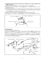
Hex. Hole Bolt 4 x 18WS [127]<127>
Ignition Coil Ass'y [128]<128>
Magneto Rotor Comp.[136]<136>
Magnetic steel portion
Gap 0.3 to 0.4 mm
3. Adjusting air gap (clearance) between the magneto rotor comp. periphery and
ignition coil ass'y
(1) Remove the Muffler Cover [4]<4>, Cylinder Cover [1]<1>, and Fan Case [118]<118>.
(2) Loosen the two Hex. Hole Bolts 4 x 18WS [127]<127> so as to tighten the Ignition Coil Ass'y
[128]<128> temporarily.
(3) Insert a thickness gauge between the magnetic steel section along the periphery of the Magneto Rotor
Comp. [136]<136> and the Ignition Coil Ass'y [128]<128>, and then adjust the position of the Ignition
Coil Ass'y [128]<128> so that the gap becomes 0.3 to 0.4 mm.
(4) Tighten the two Hex. Hole Bolts 4 x 18WS [127]<127> and remove the thickness gauge.
(5) Fully tighten the Hex. Hole Bolts 4 x 18WS [127]<127>, and then check that the gap is 0.3 to 0.4 mm.
4. Wiring diagram
Perform wiring as shown in the figure below.
Connect the Cord [134]<134> to the connector on the Ignition Coil Ass'y [128]<128>. Fasten the Cord
[135]<135> to the Ignition Coil Ass'y [128]<128> with the Hex. Hole Bolts 4 x 18WS [127]<127>. Connect
the Stop Switch Cord [107]<107> and the Ignition Coil Ass'y [128]<128> to the Stop Switch [106]<106>.
Connect the Cord [134]<134> and the Cord [135]<135> to the Stop Switch Cord [107]<107>. After wiring,
check for sparks of the Spark Plug [12]<12>.
Stop Switch Cord [107]<107>
Stop Switch [106]<106>
Cord
[134]<134>
Ignition Coil Ass'y [128]<128>
Hex. Hole Bolts
4 x 18WS
[127]<127>
Cord [135]<135>
Cord [133]<133>
Earth Cord [130]<130>
Screw [129] or
Screw M4<129>
M4 Flange
Nut [132]
Clip [131]<131>
Washer T1.6
[
16
]
<16>

-9-
Be careful of the installation angle and the press-connecting direction of the Earth Cord [130]<130>.
5. Checking the pump filter body comp.
Use a piece of wire to remove the Pump Filter Body Comp. [146]<146> from the fuel inlet of the Tank
[143]<143>. If the Pump Filter Body Comp. [146]<146> is stained, clean it with gasoline. Remove the
Pump Filter Body Comp. [146]<146> from the Shield Tube 3 x 5 x180 [137]<137>. Check the Pump Filter
Body Comp. [146]<146> for clogging by blowing air into it. Replace the Pump Filter Body Comp.
[146]<146> as necessary.
6. Cleaning the muffler (B)/muffler and cylinder
Remove the Muffler Cover [4]<4>. Loosen the two Hex. Hole Bolts 6 x 65 [6] or Hex. Hole Bolts M6 x 55
<6>, and then remove the Muffler (B) [8] or Muffler <8> together with the Heat Protection Panel [10]<10>.
Use a flat-blade (precision) screwdriver to scrape off carbon accumulated at the exhaust port of Muffler (B)
[8] or Muffler <8>. Close the exhaust port of the Cylinder Set PN [19]<19> with the Piston Set PN
[55]<54>, and then scrape off carbon accumulated at the exhaust port of the Cylinder Set PN [19]<19>.
NOTE: Do not scratch the Piston Set PN [55]<54>.
7. Cleaning the cleaner element
Open the Air Cleaner Cap [53]<52> of the Air Filter Ass'y [54]<53>. Remove the Cleaner Element
[52]<51> and clean it with compressed air. If the Cleaner Element [52]<51> is heavily stained, clean it
with gasoline and dry it well before reassembly.
8. Replacing the fuel pipe
If the Shield Tube 3 x 5 x180 [137]<137> or the Fuel Pipe 3 x 5 x 85 [138]<138> has cracks, replace it. Fit
the Shield Tube 3 x 5 x180 [137]<137> connected to the Pump Filter Body Comp. [146]<146> into the
socket on the bottom of the Carburetor Ass'y [48] as indicated with “B” in the figure below. Fit the Fuel
Pipe 3 x 5 x 85 [138]<138> into the socket on the side of the Carburetor Ass'y [48]<48> as indicated with
“C” in the figure below.
NOTE: Use parts cleaner to degrease each pipe insertion hole.
Screw [129] or
Sc
r
e
w M4<12
9
>
Flange Nut M4 [132] or
Flange Nut M14 <132>
Earth Cord [130]<130>
Ignition Coil Ass'y [128]<128>
Press-connecting portion
Washer T1.6 [16]<16>
45º±10º

-10-
Carburetor Ass'y [48]<48>
Shield Tube 3 x 5 x180 [137]<137>
Fuel Pipe 3 x 5 x 85 [138]<138>
Tank Cap Ass'y [139]<139>
Tank [143]<143>
Pump Filter Body Comp. [146]<146>
Idle adjust screw
9. Checking and adjusting the carburetor ass'y
(1) Checking the Carburetor Ass'y [48]<48>
After disassembling the Carburetor Ass'y [48]<48>, check its parts for wear, deformation, and clogged
holes. Use compressed air to remove or blow off any foreign particles or dust found. If deformation or
wear is found, replace the Carburetor Ass'y [48]<48> or its faulty parts.
(2) Adjusting the Carburetor Ass'y [48]<48>
Adjust the throttle valve opening for idling by turning the idle adjust screw. To increase the engine
speed, turn it clockwise. To reduce the engine speed, turn it counterclockwise. If the Saw Chain
[225]<225> rotates during idling, reduce the engine speed so that the Saw Chain [225]<225> does not
rotate during idling. On the other hand, if the engine speed for idling is too slow, the engine might stop
during idling. In such case, increase the engine speed within the range that inhibits the Saw Chain
[225]<225> movement.
Tank Cap Chain [140]<140>

-11-
Disassembl
y
and
r
eassembl
y
Do not reuse the following parts.
• Cover Packing [13]<13>
• Intake Packing [42]<42>
• Seal Lock Hex. Socket Hd. Bolt M5 x 30 [9]<9>
• Hex. Hole Bolt 5 x 20S [11]<11>
• Hex. Hole Bolt 4 x 12WS [15]<15>
• Seal Lock Hex. Socket Bolt (W/Washers) M5 [44]<44>
• Hex. Hole Bolt 4 x 18WS [127]<127>
• Chain Bar Knock Pin [224]<224>
1. Disassembling the engine
(1) Separating the engine from the main pipe
Loosen the Hex. Hole Bolt M5 x 12S [111]<111> and two Hex. Hole Bolts M5 x 25S [112]<112>, and
then separate the engine from the Main Pipe Comp. [170]<170>.
(2) Removing the muffler
Loosen the two Screws 5 x 16/PS [5]<5> and then remove the Muffler Cover [4]<4>. Loosen the two
Hex. Hole Bolts 6 x 65 [6] or Hex. Hole Bolts M6 x 55 <6>, and then remove the Muffler (B) [8] or
Muffler <8> and the Heat Protection Panel [10]<10> together.
(3) Removing the cylinder cover and the spark plug
Loosen the two Seal Lock Hex. Socket Hd. Bolts M5 x 30 [9]<9> and two Screws 4 x 22/PS [3]<3>,
and then remove the Cylinder Cover [1]<1>. Next, remove the plug cap from the Spark Plug [12]<12>
and then remove the Spark Plug [12]<12>.
(4) Removing the tank
Loosen the two Flange Bolts [145]<145> and the Bolt (W/Flange) L27.8 [148]<148>.
Pull out the pipe of the Shield Tube 3 x 5 x 180 [137]<137> and the Fuel Pipe 3 x 5 x 85 [138]<138>
from the Carburetor Ass'y [48]<48>. Then remove the Tank [143]<143>.
(5) Removing the air filter ass'y, carburetor ass'y, and carburetor insulator set
Open the Air Cleaner Cap [53]<52> of the Air Filter Ass'y [54]<53>, loosen the two Plus Screws 5 x
60WS [50]<50>, and then remove the Air Filter Ass'y [54]<53>, Carburetor Ass'y [48]<48>, Carburetor
Gasket [47]<47>, Throttle Wire Fixing Plate [46]<46>, and Carburetor Packing [45]<45> together.
Loosen the two Seal Lock Hex. Socket Bolts (W/Washers) M5 [44]<44>, and then remove the
Carburetor Insulator Set PN [43]<43> and the Intake Packing [42]<42> together.
(6) Removing the recoil starter body ass'y
Loosen the two Screws 4 x 22/PS [3]<3>, and then remove the Recoil Starter Body Ass'y [71]<70>.
(7) Removing the fan case and clutch drum comp.
Remove the two Screws 4 x 22/PS [3]<3> and three Seal Lock Hex. Socket Hd. Bolts M5 x 30 [9]<9>.
Place the Fan Case [118]<118>
so that its surface facing the crank case is positioned downward, while
being careful not to damage the two 4-mm cylindrical protrusions, and then remove the Stop Ring C-12
Outer [117]<117>
. After that, use a hand press or other tool to slowly push the shaft of the Clutch Drum
Comp. [119]<119> and remove it without damaging the ball bearing of the Fan Case [118]<118>.
(8) Removing the ignition coil ass'y
Loosen the two Hex. Hole Bolts 4 x 18WS [127]<127> and then remove the Ignition Coil Ass'y
[128]<128>.
(9) Removing the clutch set and starter pulley ass’y
First, to lock the Crank Shaft Ass’y [60]<59>, insert the wire rope of the recoil starter or other part into
the Spark Plug [12]<12> mounting hole on the Cylinder Set PN [19]<19>, and then turn the Magneto
Rotor Comp. [136]<136> counterclockwise until the Piston Set PN [55]<54> is locked at the top dead

-12-
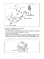
Hex. Nut M8 [125]<125>
Hammer
Crank Shaft Ass’y [60]<59>
Magneto Rotor Comp. [136]<136>
While holding the Magneto Rotor Comp.
[136]<136> by hand, use a hammer to
strike the end face of the crank shaft.
Be careful not to deform the screw thread.
center. Next, loosen the two Step Bolts [120]<120> and then remove the Clutch Set [123]<123>. To
remove the Starter Pulley Ass'y [67]<66>, lock the Crank Shaft Ass’y [60]<59> and lightly strike the
Starter Pulley Ass'y [67]<66> with a plastic hammer to turn it counterclockwise.
NOTE: Use a clean wire rope to lock the crank shaft. Also be careful not to leave cut pieces of
wire rope inside the Cylinder Set PN [19]<19>.
(10) Removing the magneto rotor comp.
Loosen the Hex. Nut M8 [125]<125>. Make the upper face of the Hex. Nut M8 [125]<125> level with
the threaded end face of the Crank Shaft Ass’y [60]<59>, and then lightly hit the end face of the
Crank Shaft Ass’y [60]<59> while holding the Magneto Rotor Comp. [136]<136> by hand to remove
it.
(11) Removing the cylinder set
Loosen the four Hex. Hole Bolts 5 x 20S [11]<11> and then slowly pull out the Cylinder Set PN
[19]<19>.
(12) Removing the piston set and piston ring
Remove the two Cir Clips [57]<56> by using long-nose pliers, lightly strike the Piston Pin [58]<57> to
remove it, and then remove the Piston Set PN [55]<54>. Remove the Piston Ring [56]<55> while
expanding the closed gap of the ring. Because the Piston Ring [56]<55> is a cast-iron part, do not
forcibly expand it. Doing so may break the ring.
(13) Removing the crank case ass’y (starter side and driving side)
Loosen the four Hex. Hole Bolts 5 x 20S [11]<11>, remove the Crank Case Ass'y [61]<60> by using a
wooden hammer to lightly strike the Crank Shaft Ass’y [60]<59>, and then remove the Crank Shaft
Ass’y [60]<59>.
2. Reassembling the engine
(1) Removing carbon
Before reassembling the engine, remove carbon from the head of the Piston Set PN [55]<54>, the
exhaust port of the Cylinder Set PN [19]<19>, and inside the combustion chamber. If the Piston Ring
[56]<55> fitted in the ring groove of the Piston Set PN [55]<54> cannot be moved smoothly, carefully
wipe off carbon from the ring groove and side surface of the Piston Ring [56]<55>. During cleaning, be
careful not to damage the surfaces of the Cylinder Set PN [19]<19> and the Piston Set PN [55]<54>.
Also remove carbon from the intake and exhaust ports of the Muffler (B) [8] or Muffler <8>.
(2) Cleaning the parts
Be sure to thoroughly clean the Crank Shaft Ass’y [60]<59>, Piston Set PN [55]<54>, and Cylinder Set
PN [19]<19> with gasoline.

-13-
Main Pipe Comp. [170] <170>
Level Mark [169]<169>
Loop Handle Ass’y Anti-vib. [161]<161>
Handle Bracket (A) [173]<173>
Bolts 6 x 43/P (Black) [174]<174>
Piston Set
PN [55]<54>
Exhaust mark (arrow)
(3) Reassembling the crank case ass’y, piston set, and cylinder set
When press-fitting the Oil Seal TB12227 [63]<62> into the
Crank Case Ass'y [61]<60>, position the pressurizing spring
inside, and then fill the gap between the lips with Pyronoc
Universal No. 0 (Nippon Oil Corp.). Dispose of the oil seal
removed at disassembly, and always use a new oil seal.
Before mounting the Cylinder Set PN [19]<19>, be sure to
apply two-cycle engine oil to the Ball Bearing 6001 C3
[64]<63>, the large and small bearings at the ends of the
connecting rod, Piston Ring [56]<55>, and the outer surface
of the Piston Set PN [55]<54>.
When mounting the Piston Set PN [55]<54>, position it so that the exhaust mark (arrow) on the top of
the piston points to the muffler. When mounting the Cylinder Set PN [19]<19>, correctly align the
closed gap of the Piston Ring [56]<55> with the lock pin at the groove in the Piston Set PN [55]<54>,
and the Cylinder Set PN [19]<19> with the Piston Set PN [55]<54>. Otherwise, the Piston Ring
[56]<55> may be easily damaged.
NOTE: If you use a new Crank Case Ass'y [61]<60>, unnecessary portion of the Crank Case
Packing [62]<61> must be cut off along the Cylinder Set PN [19]<19> matching surface
after assembling the Crank Case Ass'y [61]<60>.
(4) Reassembling the magneto rotor comp.
Mount the Magneto Rotor Comp. [136]<136> while aligning the integral key at the center hole of the
Magneto Rotor Comp. [136]<136> with the key groove in the Crank Shaft Ass’y [60]<59>.
(5) Reassembling the carburetor ass'y
When reassembling the Carburetor Ass'y [48]<48>, align the pulsed holes on the Carburetor Gasket
[47]<47> and Throttle Wire Fixing Plate [46]<46>, Carburetor Packing [45]<45>, Carburetor Insulator
Set PN [43]<43>, and Intake Packing [42]<42> with those on the Cylinder Set PN [19]<19> and
Carburetor Ass'y [48]<48>.
(6) Mounting the clutch drum comp.
While holding the inner ring of the ball bearing in the Fan Case [118]<118> so as not to damage two
4-mm cylindrical protrusions, press-fit the Clutch Drum Comp. [119]<119> and then attach the Stop
Ring C-12 Outer [117]<117>.
3. Mounting the loop handle ass’y
Position the Loop Handle Ass’y Anti-vib. [161]<161> as indicated by the Level Mark [169]<169> on the
Main Pipe Comp. [170]<170>, and then fasten the loop handle with Handle Bracket (A) [173]<173> by
evenly tightening the two Bolts 6 x 43/P (Black) [174]<174>.

-14-
4. Disassembling the gear case section
(1) Slightly loosen the Chain Bar Clamp Nut [227]<227> while being careful not to remove it.
Turn the Oil Pump Adjuster [217]<217> counterclockwise to decrease the tension of the Saw Chain
[225]<225>.
NOTE: Turning the Oil Pump Adjuster [217]<217> counterclockwise decreases the tension of
the Saw Chain [225]<225>; turning it clockwise increases the tension.
(2) Remove the Chain Bar Clamp Nut [227]<227> and the Side Cover Comp. [207]<207>, and then
remove the Chain Bar 10 [226]<226> and the Saw Chain [225]<225>.
Loosen the Hex. Hole Bolt 5 x 22/S [190]<190> and the Hex. Hole Bolt 5 x 10 [198]<198>, and then
remove the gear case ass’y from the Main Pipe Comp. [170]<170>.
(3) Open the Oil Tank Cap Ass’y [188]<188> and then drain out the chain oil from the oil tank.
Remove the four Small Screws 4 x 12WS [209]<209>, and then remove the four Collars 3 [210]<210>,
Oil Tank Cover [176]<176>, and Oil Tank Gasket [177]<177>.
Remove Stop Ring E-6 [218]<218> and turn the Oil Pump Adjuster [217]<217> (with O-ring P-5
[178]<178>) counterclockwise to remove the adjuster.
Turn the Step Bolt A [180]<180> (with the O-ring P-5 [178]<178> and the 8 Push Nut [179]<179>)
counterclockwise to remove the Step Bolt A [180]<180>.
(4) Remove the Oil Pump Comp. [181]<181> together with the Filter Ass’y [211]<211>, Fuel Pipe 3 x 5 x
60 [214]<214>, Fuel Pipe 3 x 5 x 75 [215]<215>, O-ring [182]<182>, O-ring 1.4 [183]<183>, Washer
2 [184]<184>, Oil Pump Spring [185]<185>, and Oil Pump Piston Comp. [186]<186>.
(5) Remove the Stop Ring C-24, Inner [196]<196> to remove the Pinion [192]<192>, Ball Bearing 609
[193]<193>, Ball Bearing 609Z ST [194]<194>, and Stop Ring C-9, Outer [195]<195>; however, as
these parts cannot be removed by hand, heat the Case [220]<220> and then strike with a rubber
hammer in order to pull out the Pinion [192]<192>, Ball Bearing 609 [193]<193>
, Ball Bearing 609Z
ST [194]<194>, and Stop Ring C-9, Outer
[195]<195> as a complete set.
NOTE: Be sure to wear thick cotton gloves or similar protection when holding the heated Case
[220]<220>, so as to avoid burning your hands. Also be careful not to deform the Case
[220]<220>.
(6) Use a spanner to remove the Flange Nut 6 [206]<206> with both 32 mm wide sides of the Sprocket
Comp., 3/8 [205]<205> fixed in place, and then remove the Flange Nut 6 [206]<206>, Sprocket Comp.,
3/8 [205]<205>, and Collar [204]<204> in this order. Remove the Stop Ring C-28, Inner [203]<203> to
remove the Ball Bearing 638Z [202]<202>, Gear [201]<201>, Cam [200]<200>, and Ball Bearing 627
C3 [199]<199>; however, as the Gear [201]<201> cannot be pulled out by hand, heat the Case
[220]<220> and then strike it with a rubber hammer in order to pull out the Ball Bearing 627 C3
[199]<199>, the Cam [200]<200>, Gear [201]<201>, and Ball Bearing 638Z [202]<202> as a
complete set.
NOTE: Be sure to wear thick cotton gloves or similar protection when holding the heated Case
[220]<220>, so as to avoid burning your hands. Also be careful not to deform the Case
[220]<220>.
(7) Note that the Chain Bar Tightening Bolt [222]<222> cannot be removed; therefore, replace it together
with the Case [220]<220> if the Chain Bar Tightening Bolt [222]<222> breaks or becomes unusable.
Before removing the Pinion [192]<192>, use a hand press or similar tool to remove the Stop Ring C-9,
Outer [195]<195>, Ball Bearing 609 [193]<193>, and Ball Bearing 609Z ST [194]<194> in this order.
Likewise, before removing the Gear [201]<201>, use a hand press or similar tool to remove the Ball
Bearing 627 C3 [199]<199> and the Ball Bearing 638Z [202]<202>.
NOTE: When pulling out the Ball Bearing 627 C3 [199]<199>, be careful not to damage the Cam
[200]<200>.

-15-
5. Reassembling the gear case section
(1) Reassembling the gear case section
First, press-fit the Ball Bearing 627 C3 [199]<199> into the Case [220]<220>.
NOTE: Be careful not to tilt the Ball Bearing 627 C3 [199]<199>.
Confirm that the Screw 6 x 8 [189]<189> is tightened. Apply seven to nine grams of specified Cosmo
Molybdenum No. 2 grease to the Ball Bearing 627 C3 [199]<199> in the Case [220]<220>. Set the
Cam [200]<200> on the Ball Bearing 627 C3 [199]<199>, and then press-fit the Gear [201]<201> (to
which the Ball Bearing 638Z [202]<202> is press-fitted) into the Ball Bearing 627 C3 [199]<199> in the
Case [220]<220>. Next, assemble the Stop Ring C-28, Inner [203]<203>. Press-fit the Ball Bearing
609 [193]<193> and the Ball Bearing 609Z ST [194]<194> to the Pinion [192]<192>, and then attach
the Stop Ring C-9, Outer [195]<195>. Apply 0.1 to 0.3 grams of specified Cosmo Molybdenum No. 2
grease to the gear section of the Pinion [192]<192>. Then press-fit the pinion ass’y to the Case
[220]<220> and assemble the Stop Ring C-24, Inner [196]<196>.
NOTE: Confirm that the Pinion [192]<192> rotates smoothly when turning the Gear [201]<201>.
Insert the Collar [204]<204> and the Sprocket Comp., 3/8 [205]<205> into the shaft of the Gear
[201]<201>, and then use a spanner to tighten the Flange Nut 6 [206]<206> with both 32 mm wide
sides of the Sprocket Comp., 3/8 [205]<205> fixed in place.
NOTE: Confirm that the Sprocket Comp., 3/8 [205]<205> rotates under the following operating
load.
Operating load: 1.18 N to 1.76 N (120 gf to 180 gf)
(2) Reassembling the oil tank section
Apply Turbine Oil 56 (JX Nippon Oil & Energy) to the inner and outer peripheries of the O-ring
[182]<182>, and then attach the O-ring [182]<182> to the Oil Pump Comp. [181]<181>.
Apply Primary Oil SAE30 (JX Nippon Oil & Energy) to the shaft of the Oil Pump Piston Comp.
[186]<186>, and Turbine Oil 56 (JX Nippon Oil & Energy) to the inner and outer peripheries of the
O-ring 1.4 [183]<183>. Pass the Oil Pump Spring [185]<185> and the Washer 2 [184]<184> through
the Oil Pump Piston Comp. [186]<186>, and then insert it into the Oil Pump Comp. [181]<181>.
NOTE: Confirm that the Oil Pump Piston Comp. [186]<186> operates.
Insert the assembled Oil Pump Comp. [181]<181> into the side hole of the Case [220]<220> as
passed from the oil tank to the gear chamber with the Oil Pump Piston Comp. [186]<186> side facing
up. Pass the Step Bolt A
[180]<180> through the ring section of the Oil Tank Cap Ass’y [188]<188>
and tighten the Step Bolt A [180]<180> to temporarily secure the Oil Pump Piston Comp. [186]<186>
in place. Insert the Oil Pump Adjuster [217]<217> with the O-ring P-5 [178]<178> from the front hole of
the Case [220]<220> and then tighten the adjuster so that its male screw engages with the Oil Pump
Comp. [181]<181> until the attachment groove for the Stop Ring E-6 [218]<218> of the Oil Pump
Adjuster [217]<217> protrudes from the inner side of the oil tank of the Case [220]<220>. Once the
attachment groove protrudes out, attach the Stop Ring E-6 [218]<218> to the groove.
NOTE: Before attaching the O-ring P-5 [178]<178>, apply Turbine Oil 56 (JX Nippon Oil &
Energy) to its inner periphery.
Insert the Fuel Pipe 3 x 5 x 75 [215]<215> to the end of the Banjo, Oil Pump [216]<216>.
NOTE: At that time, do not apply ethanol, oil, or other treatment to the inner periphery of the
Fuel Pipe 3 x 5 x 75 [215]<215> and the Banjo, Oil Pump [216]<216>.

-16-
Attach the Oil Tank Gasket [177]<177> to the Case [220]<220>, and then apply Turbine Oil 56
(Nippon Oil & Energy) to the O-ring P-5 [178]<178>.
Attach the Oil Tank Cover [176]<176> to the Case [220]<220> with the four Small Screws 4 x 12WS
[209]<209>, while carefully avoiding contact with the Filter Ass’y [211]<211> or the Fuel Pipe 3 x 5 x
60 [214]<214>. Because the assembly is completed at the maximum oil discharge position in this
procedure, loosen the Step Bolt A [180]<180> and adjust the Oil Pump Adjuster [217]<217> by turning
it about three-fourths to one complete rotation counterclockwise from the maximum oil discharge
position. After making this adjustment, be sure to retighten the Step Bolt A [180]<180>.
(3) Reassembling the chain bar 10 and the saw chain
Before attaching the Chain Bar 10 [226]<226>, attach the Case [220]<220> to the Main Pipe Comp.
[170]<170> according to the following procedure:
Loosen the Hex. Hole Bolt 5 x 22/S [190]<190> and the Hex. Hole Bolt 5 x 10 [198]<198> of the Case
[220]<220>, and then insert the Case [220]<220> into the Main Pipe Comp. [170]<170> until it
touches the end of the Main Pipe Comp. [170]<170> with the spline of the Drive Shaft [171]<171>
aligned with that of the Pinion [192]<192>. Align the screw hole of the Case [220]<220> with the
5.5-mm dia. hole of the Main Pipe Comp. [170]<170>, securely tighten the Hex. Hole Bolt 5 x 10
[198]<198> so as to prevent removal of the Case [220]<220> from the Main Pipe Comp. [170]<170>,
and then tighten the Hex. Hole Bolt 5 x 22/S [190]<190> to fix the Main Pipe Comp. [170]<170> and
the Case [220]<220> in place. Install the Chain Bar [226]<226> onto the Chain Bar Tightening Bolt
[222]<222>, then push it toward the Sprocket Comp., 3/8 [205]<205> as far as it will go. Make sure
that the boss of the Chain Tensioner [221]<221> fits into the hole of the Chain Bar [226]<226>.
NOTE: Slightly move the Chain Bar 10 [226]<226> back and forth and make sure the boss of the
Chain Tensioner [221]<221> fits into the hole of the Chain Bar 10 [226]<226> properly.
Confirm that the direction of the Saw Chain
[225]<225> is correct as shown in the figure,
and align the Saw Chain [225]<225> with the
Sprocket Comp., 3/8 [205]<205>. Guide the
chain drive links into the Chain Bar 10
[226]<226>
groove all around. Install the Side
Cover Comp. [207]<207>
onto the Chain Bar
Tightening Bolt [222]<222>. Then fix the Chain
Bar Clamp Nut [227]<227> temporarily. Raise
the end of the Chain Bar 10 [226]<226>, and
tighten the Saw Chain [225]<225> by turning
the Chain Tensioner [221]<221> clockwise.
• Direction of the Saw Chain [225]<225>
Chain Bar Tightening
Bolt [222]<222>
Chain Bar Knock Pin [224]<224>
Combi. Box Spanner
13 x 19 Minus
[
501
]
<501>
Chain Bar Clamp Nut [227]<227>
Sprocket Comp., 3/8
[205]<205>
Chain Bar 10
[226]<226>
Chain Bar 10
[226]<226>

-17-
To check proper tension, lightly lift up the center of the Saw Chain [225]<225> and there should be
about 0.5 to 1.0 mm clearance between the Chain Bar 10 [226]<226> and the edge of the drive link of
the Saw Chain [225]<225> (when drawing it out at load of 1 kg.)
CAUTION: PROPER TENSION IS EXTREMELY IMPORTANT!
Raise the end of the Chain Bar 10 [226]<226> and securely tighten the Chain Bar Clamp Nut
[227]<227> with the Combi. Box Spanner 13 x 19 Minus [501]<501>. The new Saw Chain [225]<225>
will stretch so adjust the Saw Chain [225]<225> after a few cuts and watch tension of the Saw Chain
[225]<225> carefully for the first half hour of cutting.
CAUTION: When the chain is excessively tightened, the bar and chain will be damaged rapidly.
Conversely, when the chain is excessively loosened, it may get out of the groove in
the bar. Always wear gloves when touching the chain.
Saw Chain [225]<225>
Chain Tensioner [221]<221>
0.5 to 1 mm

-18-
Confirmation after
r
eassembl
y
Ti
g
htenin
g
tor
q
ue
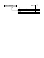
Location Part name
Thread
dia.
Tightening torque
(N•m {kgf•cm})
Crank case ass’y Hex. Hole Bolt 5 x 20S [11]<11> 5 mm 4.0 to 8.0 {41 to 81}
Cylinder Hex. Hole Bolt 5 x 20S [11]<11> 5 mm 6.0 to 9.0 {62 to 91}
Scavenging cover
ass’y
Hex. Hole Bolt 4 x 12WS [15]<15> 4 mm 2.5 to 4.5 {26 to 45}
Carburetor ass’y Plus Screw 5 x 60WS [50]<50> 5 mm 4.0 to 6.0 {41 to 61}
Carburetor insulator
plate ass’y
Seal Lock Hex. Socket Bolt (W/Washers)
M5 [44]<44>
5 mm 3.0 to 4.0 {31 to 40}
Clutch ass’y Step Bolt [120]<120> 6 mm 7.0 to 12.0 {72 to 122}
Ignition coil Hex. Hole Bolt 4 x 18WS [127]<127> 4 mm 2.7 to 4.1 {28 to 42}
Magneto rotor Hex. Nut M8 [125]<125> 8 mm 15.0 to 20.0 {154 to 204}
-
Spark Plug [12]<12> 14 mm 10.0 to 15.0 {103 to 153}
-
Starter Pulley Ass'y [67]<66> 8 mm 9.0 to 12.0 {91 to 122}
Fan case ass’y
Seal Lock Hex. Socket Hd. Bolt M5 x 30
[9]<9>
5 mm 3.5 to 4.5 {36 to 45}
Cylinder cover
Screw 4 x 22/PS [3]<3> 4 mm 2.5 to 3.5 {26 to 35}
Seal Lock Hex. Socket Hd. Bolt M5 x 30
[9]<9>
5 mm 3.5 to 4.5 {36 to 45}
Muffler
Hex. Hole Bolt 6 x 65 [6]
Hex. Hole Bolt M6 x 55 <6>
6 mm *5.5 to 9.0 {56 to 91}
Muffler cover Screw 5 x 16/PS [5]<5> 5 mm 2.0 to 3.0 {21 to 30}
Recoil starter ass’y Screw 4 x 22/PS [3]<3> 4 mm 2.5 to 3.5 {26 to 35}
Tank ass’y
Flange Bolt [145]<145> 5 mm 4.0 to 5.0 {41 to 51}
Bolt (W/Flange) L27.8 [148]<148> 5 mm 4.0 to 5.0 {41 to 51}
Handle(A), (B) Tapping Screw D4 [101]<101> 4 mm 1.5 to 2.4 {16 to 23}
Loop handle ass’y Tapping Screw 5 x 20[165]<165> 5 mm 2.4 to 3.4 {25 to 35}
Main pipe
Hex. Hole Bolt M5 x 12/S [111]<111> 5 mm 3.5 to 4.5 {36 to 45}
Hex. Hole Bolt M5 x 25/S [112]<112> 5 mm 3.5 to 4.5 {36 to 45}
Gear case ass’y
Hex. Hole Bolt 5 x 22/S [190]<190> 5 mm 3.5 to 4.5 {36 to 45}
Hex. Hole Bolt 5 x 10 [198]<198> 5 mm 3.5 to 4.5 {36 to 45}
-
Screw 6 x 8 [189]<189> 6 mm 6.0 to 7.0 {62 to 71}
Guide plate Chain Bar Knock Pin [224]<224> 6 mm 7.0 to 8.0 {72 to 81}
Sprocket comp., 3/8 Chain Bar Clamp Nut [227]<227> 8 mm 10.0 to 12.0 {103 to 122}
Oil tank cover Small Screw 4 x 12WS [209]<209> 4 mm 1.5 to 1.8 {16 to 18}
*After testing engine operation, retighten this bolt with a tightening torque of 10.0 to 12.0 N•m {102 to 122
kgf•cm}.
NOTE: Tighten the Banjo, Oil Pump [216]<216> and the Chain Bar Tightening Bolt [222]<222> until
they come into contact with each other.
• Recheck the tightening of all screws, bolts and nuts.
• Check the moving parts for any abnormality and the rotating parts for abnormal sounds.
• Check the engine for gas leaks.
• Check that the Stop Switch [106]<106> operates normally.

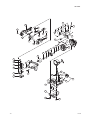
LIST NO. F021
(E1)
ENGINE
ENGINE POLE SAW
Model CS 27EPAP
2012 · 9 · 13
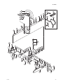
B
C
60
50
A
5
4
5
6
7
8
10
11
16
15
17
13
2
1
3
9
12
13
14
15
19
42
43
44
45
49
48
51
52
53
54
18
56
55
57
58
57
11
61
62
63
64
65
59
64
63
66
67
68
69
70
72
73
74
75
76
77
3
78
79
80
71
65
46
47
21
22
25
27
35
36
37
20
32
23
26
28
29
30
31
33
34
38
39
40
41
24
Page is loading ...
Page is loading ...
Page is loading ...
Page is loading ...
Page is loading ...
Page is loading ...
Page is loading ...
Page is loading ...
Page is loading ...
Page is loading ...
Page is loading ...
Page is loading ...
Page is loading ...
Page is loading ...
Page is loading ...
-
 1
1
-
 2
2
-
 3
3
-
 4
4
-
 5
5
-
 6
6
-
 7
7
-
 8
8
-
 9
9
-
 10
10
-
 11
11
-
 12
12
-
 13
13
-
 14
14
-
 15
15
-
 16
16
-
 17
17
-
 18
18
-
 19
19
-
 20
20
-
 21
21
-
 22
22
-
 23
23
-
 24
24
-
 25
25
-
 26
26
-
 27
27
-
 28
28
-
 29
29
-
 30
30
-
 31
31
-
 32
32
-
 33
33
-
 34
34
-
 35
35


Hitachi CS 27EPA(S) User manual
- Category
- Power chainsaws
- Type
- User manual
- This manual is also suitable for
Ask a question and I''ll find the answer in the document
Finding information in a document is now easier with AI
Related papers
-
Hitachi CS33ET Technical Data And Service Manual
-
-
-
-
-
-
Hitachi CS 33EDT User manual
-
-
Hitachi cs 40 ea User manual
-
Other documents
-
CMI 182-6560 Installation guide
-
Dataflex 49.450 Datasheet
-
-
-
 Pfister G134-3444 Operating instructions
-
BodyCraft F605 F/I/D Owner's manual
-
Bolens 247.29773 User manual
-
RedMax SGCZ2500S User manual
-
MTD 134-480A User manual
-
Zenoah Sweeper RMSZ2500 User manual
