Page is loading ...

SECTION: 6.10.082
FM2540
0813
Supersedes
0613
MODEL 503
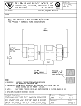
WATER POWERED EMERGENCY BACKUP
SUMP PUMP SYSTEM
PVC CONSTRUCTION
PREINSTALLATION CHECKLIST
1. Inspect your pump. Occasionally, products are damaged during shipment. If the unit or any of the parts are damaged, contact
your dealer before using.
2. Read all the installation instructions regarding installing and start up before performing any of the work described within.
Retain for future reference.
SEE BELOW FOR LIST OF WARNINGS
1. For your protection always disconnect the power supply
from its power source before handling the components of
your primary pump.
2. Sump water is non-potable. To reduce the risk of contamination
of the potable water supply, the Home Guard
®
Max must
be installed with a listed backow device suitable for the
installation, in accordance with the local plumbing code,
such as a reduced pressure principle backow preventer
(RP). Alternately, consult the local plumbing and health
codes or the authority having jurisdiction for guidance on
cross-connection and backow protection requirements.
CAUTION
SEE BELOW FOR LIST OF CAUTIONS
CAUTION
Turbulence caused by high velocity incoming
water can negatively affect the on/off action of the oat
mechanism. If this condition exists, the incoming water must
be bafed to avoid excessive turbulence.
®
REFER TO WARRANTY ON PAGE 2.
1. This pump is designed for handling clear water. Do not use in
septic tanks to pump efuent or sewage pits to pump sewage.
2. Repair and service of your backup system should be performed
by an authorized service station.
3. The installation of this backup pump requires the use of a
variable level oat switch for operation. It is the responsibility
of the installing party, to ensure that the oat switch will not
hang up on the pump apparatus or pit peculiarities and is
secured so the pump will turn “on” and “off”. It is recommended
that the pit be 18" in diameter or larger to accommodate both
a primary and a backup pump.
4. Check the installation of the primary and backup pump oats
to ensure that both move freely and are not being encroached
upon where the oat cannot move. Adequate space between
the oats must be maintained.
5. The pump should be manually activated once a month by
lifting the oat rod. Let the pump run for at least 15 seconds
to prevent the pump from building up calcium deposits and
debris, which could harm the pump.
© Copyright 2013 Zoeller Co. All rights reserved.
U
P
C
®
C
NEW ARTWORK MUST BE SENT TO LINCOLN WHEN CHANGES ARE MADE
Product information presented
here reects conditions at time
of publication. Consult factory
regarding discrepancies or
inconsistencies.
MAIL TO: P.O. BOX 16347 • Louisville, KY 40256-0347
SHIP TO: 3649 Cane Run Road • Louisville, KY 40211-1961
(502) 778-2731 • 1 (800) 928-PUMP • FAX (502) 774-3624
visit our web site:
www.zoeller.com
®
Your Peace of Mind is Our Top Priority
®

2
LIMITED WARRANTY
Manufacturer warrants, to the purchaser and subsequent owner
during the warranty period, every new product to be free from
defects in material and workmanship under normal use and
service, when properly used and maintained, for a period of three
years from date of manufacture. Parts that fail within the warranty
period, that inspections determine to be defective in material or
workmanship, will be repaired, replaced or remanufactured at
Manufacturer's option, provided however, that by so doing we
will not be obligated to replace an entire assembly, the entire
mechanism or the complete unit. No allowance will be made
for shipping charges, damages, labor or other charges that may
occur due to product failure, repair or replacement.
This warranty does not apply to and there shall be no warranty for
any material or product that has been disassembled without prior
approval of Manufacturer, subjected to misuse, misapplication,
neglect, alteration, accident or act of nature; that has not
been installed, operated or maintained in accordance with
Manufacturer's installation instructions; that has been exposed to
outside substances including but not limited to the following: sand,
gravel, cement, mud, tar, hydrocarbons, hydrocarbon derivatives
(oil, gasoline, solvents, etc.), or other abrasive or corrosive
substances, wash towels or feminine sanitary products, etc. in
all pumping applications. The warranty set out in the paragraph
above is in lieu of all other warranties expressed or implied;
and we do not authorize any representative or other person to
assume for us any other liability in connection with our products.
Contact Manufacturer at, 3649 Cane Run Road, Louisville,
Kentucky 40211, Attention: Customer Support Department to
obtain any needed repair or replacement of part(s) or additional
information pertaining to our warranty.
MANUFACTURER EXPRESSLY DISCLAIMS LIABILITY FOR
SPECIAL, CONSEQUENTIAL OR INCIDENTAL DAMAGES OR
BREACH OF EXPRESSED OR IMPLIED WARRANTY; AND
ANY IMPLIED WARRANTY OF FITNESS FOR A PARTICULAR
PURPOSE AND OF MERCHANTABILITY SHALL BE LIMITED
TO THE DURATION OF THE EXPRESSED WARRANTY.
Some states do not allow limitations on the duration of an implied
warranty, so the above limitation may not apply to you. Some
states do not allow the exclusion or limitation of incidental or
consequential damages, so the above limitation or exclusion
may not apply to you.
This warranty gives you specic legal rights and you may also
have other rights which vary from state to state.
Do’s And Don’ts For Installing A Unit
1. DO read all installation materials supplied with the pump.
2. DO inspect unit for any visible damage caused by shipping.
Contact dealer if unit appears to be damaged.
3. DO clean all debris from the pit before installation.
4. DO install a union check valve (see STEP 3) in the
discharge line. DO NOT use a discharge pipe smaller than
the recommended pump discharge sizes.
5. DO install a lter or strainer in the water supply line before the
pump to prevent small particles from clogging the operating
valve.
6. DO test the pump immediately after installation to be sure
that the system is working properly.
7. DO review all applicable local and national codes and verify
that the installation conforms to each of them.
8. DO NOT use the Home Guard
®
Max with hot water.
DO NOT use the Home Guard
®
Max to remove wastewater,
sewage, efuent, or water with debris in it.
9. DO NOT use a garden hose. Garden hose is not designed
to hold municipal pressure indenitely and could leak or
burst causing ooding. The Home Guard
®
Max requires a
permanent piping method such as copper, PEX, or CPVC.
10. DO install the Home Guard
®
Max pump with only a ¾"
supply line.
11. DO install a union or other quick-disconnect tting to make
the pump accessible for servicing on both the water supply
and discharge piping.
12. DO install a dedicated shut-off valve on the water supply line
within 6 ft. (1.8 m) of the Home Guard
®
Max.
Helpful Hints For Easy Installation
1. The system is designed for installation in sumps with minimum
diameter of 18” and depth of 22”. For smaller applications,
consult factory.
2. Remove all debris from the pit before installation.
3. Be sure that the pump is clamped securely to the primary
pump discharge pipe and that the two pumps do not interfere
with each other.
4. Install a serviceable check valve in the discharge line.
5. Install a lter or strainer in the water supply line before the
pump. Size the lter/strainer properly to minimize pressure
drop, while retaining particles 0.020" (0.5 mm) in diameter
and larger.
6. Test the unit immediately after installation. Refer to STEP 5.
7. Check the Float ON/OFF levels per STEP 2 of the instructions.
8. Keep the model number, date code, and installation
instructions in a convenient location for future reference.
© Copyright 2013 Zoeller Co. All rights reserved.
In those instances where damages are incurred as a result of an alleged pump failure, the homeowner must
retain possession of the pump for investigation purposes.

3
INSTALLATION
The Home Guard
®
MAX pump can be installed very easily as a standby to an electric sump pump (see sketches).
Sump water is non-potable. To reduce the risk of contamination of the potable water supply, the Home Guard
®
Max must
be installed with a listed backow device suitable for the installation, in accordance with the local plumbing code, such
as a reduced pressure principle backow preventer (RP). Alternately, consult the local plumbing and health codes or the
authority having jurisdiction for guidance on cross-connection and backow protection requirements.
STEP 1: Placement of the Pump in the Pit
Note: If your pit has a cover, it will have to be modied to accommodate the Home Guard
®
Max pump.
1.1) Inspect the pit for debris and clean as necessary.
1.2) Place the pump in the pit, making certain that the inlet tting of the pump is at least 6” above the basement oor or top of the
sump pit. Ensure the pump is clamped securely to the primary pump discharge pipe. Mark the location on the discharge pipe.
IMPORTANT
This pump is to be used as a backup to your primary pump. Make certain that there is no interference between the
two pumps, especially between the oat systems.
STEP 2: Pump Float Stop Adjustment
2.1) With the Home Guard
®
Max pump in the pit, measure the desired oat ON position (this should be a few inches above the
ON level of the existing pump). The pump turns on at a water level of 2” to 3” below the upper oat stop, depending on the
incoming water pressure. Calculate the appropriate oat stop location based on this distance.
2.2) The OFF level is determined by the buoyancy of the oat as well as the incoming water pressure, roughly 6” to 8” below the
ON level. The OFF level must be above the suction screen of the foot valve. Adjusting the lower oat stop will not change
the OFF level of the pump. It is recommended to install the lower stop tight to the bottom of the oat so that it cannot move
on the oat rod.
2.3) Remove the pump from the pit and adjust the oat stops as necessary. Tighten all screws. Be sure to tighten the lower
stop properly so that it will not come off. If the lower stop comes off, the oat can drop off the oat rod, rendering the pump
non-operational and possibly damaging the pump.
2.4) Replace the pump in the pit at the same location on the primary pump discharge pipe as marked earlier (Step 1.2). This will
ensure that the ON and OFF levels are consistent with the calculations.
STEP 3: Installation of the Discharge Piping
3.1) Glue 1½" pipe into the pump discharge connection as shown in the gure on page 5 (reference SK2721).
3.2) Per the Uniform Plumbing Codes and IAPMO PS119, the discharge of the water-powered sump pump should not be
connected to the discharge of the primary sump pump. The discharge piping for water-powered sump pumps must have
an air gap and extend outside of the building, with the end of the pipe between 6 and 24 in. (150 and 610 mm) above the
ground or the ood level of the area receiving the discharge.
3.3) In order for this installation to work properly, a check valve must be installed onto the discharge line. The following Zoeller
check valves are recommended: 30-0100; 30-0101; 30-0102; 30-0103. Some local codes require a union check with ball
valve. Check your local code requirements to ensure that the installation complies.
STEP 4: Installation of the Source Water Piping
Sump water is non-potable. To reduce the risk of contamination of the potable water supply, the Home Guard
®
Max must
be installed with a listed backow device suitable for the installation, in accordance with the local plumbing code, such
as a reduced pressure principle backow preventer (RP). Alternately, consult the local plumbing and health codes or the
authority having jurisdiction for guidance on cross-connection and backow protection requirements.
© Copyright 2013 Zoeller Co. All rights reserved.

4
4.1) Shut off the municipal water supply and plumb ¾" tubing/piping into the municipal water supply line. This must be branched
off of a ¾" line and plumbed with ¾" tubing/piping to the Home Guard
®
Max . Do not use garden hose or other exible hose/
tubing. Install a shut off valve in the ¾" supply line to the Home Guard
®
Max. Use the appropriate back-ow prevention for
your jurisdiction. Supply piping shall be made of materials and methods approved by the local plumbing codes.
4.2) Do not braze/solder copper ttings within 18” of Home Guard
®
Max, as the heat from the torch will damage the pump body.
4.3) When assembling threaded ttings into the Home Guard
®
Max inlet, do not use pipe dope on the inlet threads, use PTFE
(Teon
®
) sealing tape. Take special care to keep any debris (including pieces of tape) from entering the inlet tting that might
get caught in the operating valve.
4.4) The Home Guard
®
Max includes a eld installed Push-to-Connect tting. This tting is designed to be used with ¾” PEX,
CPVC, or copper pipe. The tting must be installed on the ¾" NPT thread of the pump inlet tting. Caution must be used
when installing the tting to not over tighten the inlet tting and crack the body. Using a backup wrench, hold the
inlet tting while tightening the Push-to-Connect tting. If the Push-to-Connect tting is not used, the same precaution
must be used when installing any other tting to the inlet tting. A union or quick-disconnect tting should be installed to
make the pump accessible for servicing.
4.5) Purge the water line prior to connecting to the Home Guard
®
Max to ensure that debris does not enter the unit and clog the
operating valve. Install a dedicated shut-off valve on the water supply line within 6 ft. (1.8 m) of the Home Guard
®
Max.
4.6) If using the Push-to-Connect tting, cut the tube so that the ends are square. Ensure that there are no burrs or damage to
the cut end. Once the tubing end is cut square and clean, scribe a depth mark on the outside of the tubing 1” from the end.
Insert the tube through the release collar to rest against the grab ring. Push the tube rmly with a slight twisting action until
it reaches the tube stop. The depth mark should be up to the end of the release collar. The tube liner is not necessary with
CPVC or Copper tubing, and may be removed based on preference or local codes. The tube liner can be easily removed by
pulling it out with a needle nosed pliers.
4.7) Once the pump has been installed and the municipal water source connected, slowly open the municipal water source valve
and the supply line valve. Inspect the valve body and all connections looking for leaks. Close the municipal water valve and
x any leaks before operating the pump.
STEP 5: Testing of Pump Operation
5.1) Unplug the primary pump so that it does not start.
5.2) Fill the sump with water until the Home Guard
®
Max starts. NOTE: The sump must be full of water for the pump to shut off properly.
5.3) Verify that the pump starts and stops at the desired ON/OFF points.
5.4) Verify that there are no leaks in the discharge line.
5.5) If adjustment is necessary, raise or lower the stops according to STEP 2.
5.6) If the pump is not operating properly after following the above steps, refer to the Troubleshooting guide.
5.7) When nished testing, plug primary pump back into AC receptacle.
5.8) Adjust alarm reed switch (optional) to desired level, if necessary. Refer to FM2571 for Alarm System Instructions. Be sure
to install 9V battery in Alarm Panel.
WATER PRESSURE:
20 PSI minimum with valve open.
80 PSI maximum with valve open.
100 PSI maximum with valve closed.
EFFICIENCY:
The pumping capacity increases with household water pressure and ow.
At an eight-foot static head and a supply pressure of 20 PSI at water supply inlet with water owing, it takes one (1) gallon of
supply water to remove one gallon from the sump. As the supply pressure increases with the static head constant, less supply
water is required.
INSTALLATION, continued
© Copyright 2013 Zoeller Co. All rights reserved.
STEP 4: continued

5
SK2720
SUCTION
DISCHARGE
3/4 NPT
WATER SUPPLY
1 1/2
SLIP FIT
HOSE CLAMPS FOR
ATTACHING TO PRIMARY
PUMP DISCHARGE PIPE
ON LEVEL
PRIMARY PUMP
FLOAT
ON/OFF
PUMP
SUBMERSIBLE
CHECK VALVES
ABOVE SUCTION SCREEN
OFF LEVEL MUST BE
COUPLINGS
PLUG
3-PRONG
AND ABOVE PRIMARY
PUMP ON LEVEL
BY TESTING. SEE INSTRUCTIONS.
ON LEVEL TO BE DETERMINED
INCOMING WATER
SUPPLY LINE
6" MIN.
BACK FLOW PREVENTER
AND FILTER
(SUPPLIED BY OTHERS)
(SUPPLIED BY OTHERS)
ALARM MAY BE SET TO SOUND PRIOR
TO BACKUP PUMP TURNING ON.
THIS WILL WARN OF MAIN PUMP FAILURE.
IF DESIRED, THE ALARM CAN BE SET TO
SOUND WHEN BACKUP PUMP ACTIVATES.
THIS WILL WARN THAT BACKUP PUMP IS
ON OR HAS FAILED.
(OPTIONAL ALARM)
INSTALL DEDICATED SHUT-OFF
VALVE WITHIN 6FT. (1.8M)
OF HOMEGUARD MAX.
"A-PAK" ALARM SYSTEM
Note: Replace battery every 12 months
INDOOR ALARM SYSTEM 120VAC
TEST
SILENCE
R
WARNING:
ELECTRICAL SHOCK
HAZARD
FAILURE TO DISCONNECT ALL
POWER BEFORE SERVICING
COULD RESULT IN INJURY OR DEATH.
LR54245
LISTED
288X
POWER ON
ALARM
10-1494
R
LOUISVILLE, KY
R
R
PIPING ASSEMBLY
SK2721
TYPICAL INSTALLATION WITH SUBMERSIBLE PUMP
AND SEPARATE DISCHARGE PIPE
PUMP DETAILS
© Copyright 2013 Zoeller Co. All rights reserved.

6
018586
TOTAL DYNAMIC HEAD
FLOW PER MINUTE
15
LITERS
0
GALLONS
20 40
5 10
0
2
5
25
8060
20
PUMP PERFORMANCE
CURVE
MODEL 503
FEET
METERS
4
10
15
6
45
30
25
20
40
35
8
10
12
14
20 PSI
40 PSI
60 PSI
80 PSI
TOTAL DYNAMIC HEAD/FLOW
PER MINUTE
DEWATERING ONLY
PERFORMANCE CHARACTERISTICS
CONDITION POSSIBLE CAUSE REMEDY
A
PUMP WILL NOT START
OR RUN
Inadequate incoming water
pressure.
Check incoming water line for closed valve, low water
pressure or clogged lter/strainer.
Excessive incoming water
pressure.
Install regulator and reduce pressure below 100 PSI
with valve closed.
Debris around Intake. Clear debris from pit and foot valve strainer.
Float hung up on pit or primary
pump
Move pumps so that the oats move freely and do not
contact pit, piping or each other.
B PUMP STARTS TOO SOON Float "ON" point is adjusted too low. Refer to STEP 2.
C
PUMP WILL NOT SHUT
OFF
Float is obstructed. Inspect oat operation and correct problem.
Float "OFF" point is adjusted too low. Refer to STEP 2.
Foot Valve above water level. Adjust Float - Refer to STEP 2.
Internal valve diaphragm vent
hole is plugged with debris.
Turn off water supply to pump and back on repeatedly
to dislodge debris. If this process does not remedy
the problem, service pump to clear debris or replace
valve assembly.
Water level in sump pit was
below foot valve when pump was
activated.
Turn off water supply to pump. Fill pit with water until
the foot valve is submerged. Turn on water supply
and activate oat by hand. Allow pump to run for 3-5
seconds and release oat before the foot valve is
above the water level. Pump should shut off normally.
D
PUMP OPERATES BUT
DELIVERS LITTLE OR NO
WATER
Debris around Intake. Clear debris from pit and foot valve strainer.
Inadequate incoming water
pressure.
Check incoming water line for closed valve or low
water pressure.
Blockage in discharge pipe. Remove pipe and ush out debris.
Foot Valve above water level. Adjust Float - Refer to STEP 2.
Vertical lift too high. Change discharge piping or contact technical service.
Troubleshooting Guide
© Copyright 2013 Zoeller Co. All rights reserved.
Pump capacity varies due to: Inlet Water Pressure, Working Water Pressure, Discharge
Elevation, Number of Pipe Fittings, Inlet and Outlet Pipe Size, Fluid Viscosity, Degree of Water
Clarity, Water Temperature. The ow rates in the chart are approximate values.
NOTE: Some districts may require a reduced pressure principle backow preventer per ASSE
Standards 1013. Check Local Codes.
Sump water is non-potable. To reduce the risk of contamination of the potable
water supply, the Home Guard
®
Max must be installed with a listed backow
device suitable for the installation, in accordance with the local plumbing code, such as a
reduced pressure principle backow preventer (RP). Alternately, consult the local plumbing
and health codes or the authority having jurisdiction for guidance on cross-connection and
backow protection requirements.

7
ILLUSTRATED PARTS BREAKDOWN
HOME GUARD
®
SERVICE PARTS - MODEL 503 503-A&B 503-C 503-D 503-E
ITEM DESCRIPTION QTY NOTES
10/08
thru
02/10
03/10
thru
10/10
11/10
thru
05/11
06/11
thru
Current
1 Clamps 2 * 001766 001766 001766 001766
2 Backow valve assembly 1 018587 018587 018587 018587
3 Push connect tting 1 018584 018584 018584 018584
4 Diaphragm and O-ring 1 * 018588 150553 150553 150553
5 Plunger assembly 1 * 018589 018589 018589 018589
6 Nozzle seat 1 018588 018588 018588 151713
7 Spring 1 * 018564 018564 018564 018564
8 Float rod magnet guide assembly 1 150084 150084 150084 150084
9 Float rod guide 1 150085 150085 150741 150741
10 Float stop assembly 2 * 054085 054085 054085 054085
11 Float 1 018567 018567 018567 018567
12 Venturi 1 4C5534 4C5534 4C5534 4C5534
13 Foot valve 1 ** 150260 150260 150260 150260
14 Valve assemby 1 150101 150101 150101 150101
15 Screws 6 * 001885 001885 001885 001885
16
Float rod, long
1
018583 018583 018583 018583
Float rod, short N/A N/A N/A 151708
* Rebuild kit 1 150086 150554 150554 150554
* Items included in rebuild kit.
** Foot valve will need to be cut off as close to top of valve as possible and a new one glued in place.
SK2741
© Copyright 2013 Zoeller Co. All rights reserved.

8
© Copyright 2013 Zoeller Co. All rights reserved.
MAIL TO: P.O. BOX 16347 • Louisville, KY 40256-0347
SHIP TO: 3649 Cane Run Road • Louisville, KY 40211-1961
(502) 778-2731 • 1 (800) 928-PUMP • FAX (502) 774-3624
Your Peace of Mind is Our Top Priority
®
®
visit our web site:
www.zoeller.com

13
© 2013 Zoeller Co. Todos los derechos reservados.
SK2721B
INSTALACIÓN TÍPICA CON BOMBA SUMERGIBLE
Y TUBERÍA DE DESCARGA SEPARADA
DETALLES DE LA BOMBA
SK2720
ABRAZADERAS DE
MANGUERA PARA
CONECTAR LA UNIDAD A
LA TUBERÍA DE DESCARGA
DE LA BOMBA PRIMARIA
CONEXIÓN
DESLIZANTE
DE 1-1/2
PULGADAS
DESCARGA
SUCCIÓN
SUMINISTRO DE AGUA DE
3/4 PULG. NPT
"A-PAK" ALARM SYSTEM
Note: Replace battery every 12 months
INDOOR ALARM SYSTEM 120VAC
TEST
SILENCE
R
WARNING:
ELECTRICAL SHOCK
HAZARD
FAILURE TO DISCONNECT ALL
POWER BEFORE SERVICING
COULD RESULT IN INJURY OR DEATH.
LR54245
LISTED
288X
POWER ON
ALARM
10-1494
R
LOUISVILLE, KY
R
R
CONJUNTO DE TUBERÍAS
(SUMINISTRADO POR OTROS)
ACOPLADORES
TUBERÍA DE
SUMINISTRO
DE AGUA
DISPOSITIVO
ANTIRRETORNO Y FILTRO
(PROVISTO POR OTRO)
EL NIVEL DE APAGADO DEBE
ESTAR POR ENCIMA DE LA
REJILLA DE SUCCIÓN Y DEL
NIVEL DE ENCENDIDO DE LA
BOMBA PRIMARIA
FLOTADOR DE
ACTIVACIÓN
BOMBA SUMERGIBLE
NIVEL DE ENCENDIDO
DE LA BOMBA PRIMARIA
ENCHUFE DE 3
PATILLAS
VÁLVULAS DE
RETENCIÓN
15,2 CM (6 PULGADAS) MÍN.
(ALARMA OPCIONAL)
EL NIVEL DE LA ALARMA DEBE
ESTAR POR ENCIMA DEL NIVEL
DE ENCENDIDO DE LA BOMBA
DE RESPALDO
INSTALE UNA VÁLVULA
DE APAGAR DENTRO
DE 1.8 M (6 PIES) DEL
HOME GUARD
®
MAX
NIVEL DE ENCENDIDO
DETERMINADO POR
PRUEBA. VER LAS
INSTRUCCIONES.

15
© 2013 Zoeller Co. Todos los derechos reservados.
DESGLOSE DE LOS COMPONENTES EN LA ILUSTRACIÓN
SK2741
REPUESTOS DE HOME GUARD
®
MAX - MODELO 503 503-AaB 503-C 503-D 503-E
ÍTEM DESCRIPCIÓN CANT. NOTAS
Del
10/08 a
02/10
Del
03/10 a
10/10
Del
11/10 a
5/10
Del
6/11 a
la fecha
1 Abrazadera 2 * 001766 001766 001766 001766
2 Conjunto de la válvula de contraujo 1 018587 018587 018587 018587
3 Conexión de presión 1 018584 018584 018584 018584
4 Diafragma y junta tórica 1 * 018588 150553 150553 150553
5 Conjunto del émbolo 1 * 018589 018589 018589 018589
6 Base de la tobera 1 018588 018557 018557 018557
7 Resorte 1 * 018564 018564 018564 018564
8 Conjunto de la guía imantada de la varilla del otador 1 150084 150084 150084 150084
9 Guía de la varilla del otador 1 150085 150085 150741 150741
10 Conjunto del tope del otador 2 * 054085 054085 054085 054085
11 Flotador 1 018567 018567 018567 018567
12 Venturi 1 4C5532 4C5532 4C5532 4C5532
13 Válvula de pie 1 ** 150260 150260 150260 150260
14 Conjunto de la válvula 1 150101 150101 150101 150101
15 Tornillo 6 * 001885 001885 001885 001885
16
Varilla del otador, larga
1
018583 018583 018583 018583
Varilla del otador, corta --- --- --- 151708
* Juego de reposición 1 150086 150554 150554 150554
* Ítems incluidos en el juego de reposición.
** La válvula de pie se debe cortar lo más cerca posible de la parte superior y la válvula nueva se debe jar con pegamento.

21
SK2720
SK2721B
INSTALLATION TYPIQUE À DIMENSIONS DE POMPE
SUBMERSIBLE ET CONDUITE DE REFOULEMENT DISTINCTE
RENSEIGNEMENTS
BRIDES DE SERRAGE DE
FIXATION AU TUYAU DE
REFOULEMENT DE LA
POMPE PRIMAIRE
RACCORD
GLISSANT DE
1 ½ PO
REFOULEMENT
ASPIRATION
ALIMENTATION
D’EAU NPT 3/4
© Copyright 2013 Zoeller Co. Tous droits réservés.
"A-PAK" ALARM SYSTEM
Note: Replace battery every 12 months
INDOOR ALARM SYSTEM 120VAC
TEST
SILENCE
R
WARNING:
ELECTRICAL SHOCK
HAZARD
FAILURE TO DISCONNECT ALL
POWER BEFORE SERVICING
COULD RESULT IN INJURY OR DEATH.
LR54245
LISTED
288X
POWER ON
ALARM
10-1494
R
LOUISVILLE, KY
R
R
TUYAUTERIE (FOURNIE
PAR DES TIERS)
RACCORDS
CANALISATION
D’AMENÉE D’EAU
DISPOSITIF ANTI-
REFOULEMENT ET FILTRE
(FOURNIS PAR D'AUTRES)
LE NIVEAU D’ARRÊT DOIT SE
TROUVER AU-DESSUS DE LA
CRÉPINE D’ASPIRATION ET DU
NIVEAU DE DÉMARRAGE DE LA
POMPE PRIMAIRE
FLOTTEUR
MARCHE-ARRÊT
POMPE
SUBMERSIBLE
NIVEAU DE
DÉMARRAGE DE LA
POMPE PRIMAIRE
NIVEAU DE DÉMARRAGE
À DÉTERMINER PAR
UN ESSAI. VOIR LES
DIRECTIVES.
FICHE À TROIS
BROCHES
CLAPETS DE
NON-RETOUR
MINI 15,2 CM (6 PO)
(ALARME
OPTIONNELLE)
LE NIVEAU DE L’ALARME
DOIT SE TROUVER
AU-DESSUS DU NIVEAU
MARCHE DE LA POMPE
DE RÉSERVE
INSTALLEZ UNE SOUPAPE
D'ARRÊT EN EAU À 1,8 M
(6 PI) DU HOME GUARD
®
MAX

23
VUE ÉCLATÉE
SK2741
PIÈCES DE RECHANGE HOMEGUARD – MODÈLE 503 503-A au B 503-C 503-D 503-E
ART. DESCRIPTION QTÉ REMARQUES
du
08/10 au
02/10
du
03/10 au
10/10
du
11/10 au
5/11
du
6/11 au
présent
1 collier de serrage 2 * 001766 001766 001766 001766
2 dispositif de non-retour 1 018587 018587 018587 018587
3 Raccord enclenchable 1 018584 018584 018584 018584
4 diaphragme et joint torique 1 * 018588 150553 150553 150553
5 piston 1 * 018589 018589 018589 018589
6 siège d’injecteur 1 018588 018557 018557 018557
7 ressort 1 * 018564 018564 018564 018564
8 guide de l’aimant de la tige de otteur 1 150084 150084 150084 150084
9 guide de la tige de otteur 1 150085 150085 150741 150741
10 butée du otteur 2 * 054085 054085 054085 054085
11 otteur 1 018567 018567 018567 018567
12 venturi 1 4C5532 4C5532 4C5532 4C5532
13 clapet de pied 1 ** 150260 150260 150260 150260
14 ensemble de vanne 1 150101 150101 150101 150101
15 vis 6 * 001885 001885 001885 001885
16
tige de otteur - longue
1
018583 018583 018583 018583
tige de otteur - courte s/o s/o s/o 151708
* kit de remise à neuf 1 150086 150554 150554 150554
* Pièces comprises dans le kit de remise à neuf.
** Il faut couper le clapet de pied aussi proche que possible du haut de la valve et en coller un nouveau à la place.
© Copyright 2013 Zoeller Co. Tous droits réservés.

© Copyright 2013 Zoeller Co. Tous droits réservés.
Your Peace of Mind is Our Top Priority
®
®
Visitrez notre site internet:
www.zoeller.com
ADRESSE POSTALE : P.O. BOX 16437 • Louisville, KY 40256-0347 USA
ADRESSE PHYSIQUE : 3649 Cane Run Road • Louisville, KY 40211-1961 USA
TÉL : +1 (502)778-2731 • FAX +1 (502) 774-3624
/