Zoeller Pump Co 900-0002 Installation guide

Type
Installation guide

Zoeller Pump Co 900-0002 is an advanced prepackaged system designed for effluent and dewatering applications. This model combines a 24" x 30" duplex basin assembly with the M53 grinder pump and Pro Pak backup system to provide reliable and efficient wastewater handling. The M53 grinder pump effectively macerates solids, preventing clogging and ensuring smooth operation. The Pro Pak backup system adds an extra layer of protection against pump failure or power outages, ensuring uninterrupted wastewater removal.

Zoeller Pump Co 900-0002 is an advanced prepackaged system designed for effluent and dewatering applications. This model combines a 24" x 30" duplex basin assembly with the M53 grinder pump and Pro Pak backup system to provide reliable and efficient wastewater handling. The M53 grinder pump effectively macerates solids, preventing clogging and ensuring smooth operation. The Pro Pak backup system adds an extra layer of protection against pump failure or power outages, ensuring uninterrupted wastewater removal.

1
© Copyright 2012 Zoeller Co. All rights reserved.
INSTALLATION INSTRUCTIONS
MODEL 900 PREPACKAGED SYSTEMS
P/N 152042
Notice to installing contractor: Instructions must remain with installation.
SECTION: 6.10.071
FM 2681
0312
Supersedes
New
PREINSTALLATION CHECKLIST - ALL INSTALLATIONS
DATE INSTALLED:
MODEL NUMBER:
1. Inspect your pump. Occasionally, products are damaged during shipment. If the unit is damaged, contact your dealer before using. DO NOT remove the test
plugs in the cover nor the motor housing.
2. Carefully read the literature provided to familiarize yourself with specific details regarding installation and use. These materials should be retained
for future reference.
Product information presented
here reects conditions at time
of publication. Consult factory
regarding discrepancies or
inconsistencies.
MAIL TO: P.O. BOX 16347 • Louisville, KY 40256-0347
SHIP TO: 3649 Cane Run Road • Louisville, KY 40211-1961
(502) 778-2731 • 1 (800) 928-PUMP • FAX (502) 774-3624
visit our web site:
www.zoeller.com
®
Your Peace of Mind is Our Top Priority ®
EFFLUENT/SUMP/DEWATERING
900-0008 24 x 24 Simplex Basin Assembly with Pro Pak Backup System
900-0009 24 x 30 Duplex Basin Assembly with M53 and Pro Pak Backup System
SEE BELOW FOR LIST OF WARNINGS
1. Make certain that the receptacle is within the reach of the pump’s power supply cord. DO
NOT USE AN EXTENSION CORD. Extension cords that are too long or too light do not deliver
sufcient voltage to the pump motor. But, more important, they could present a safety hazard if
the insulation were to become damaged or the connection end were to fall into the sump.
2. Make sure the pump electrical supply circuit is equipped with fuses or circuit breakers of
proper capacity. A separate branch circuit is recommended, sized according to the “National
Electrical Code” for the current shown on the pump nameplate.
3. Testing for ground. As a safety measure, each electrical outlet should be checked for ground
using an Underwriters Laboratory Listed circuit analyzer which will indicate if the power, neutral and
ground wires are correctly connected to your outlet. If they are not, call a qualied licensed electrician.
4. For Added Safety. Pumping and other equipment with a 3-prong grounded plug must be
connected to a 3-prong grounded receptacle. For added safety the receptacle may be protected
with a ground-fault circuit interrupter. When a pump needs to be connected in a watertight junction
box, the plug can be removed and spliced to the supply cable with proper grounding. For added
safety this circuit may be protected by a ground-fault circuit interrupter. The complete installation
must comply with the National Electrical Code and all applicable local codes and ordinances.
5. FOR YOUR PROTECTION, ALWAYS DISCONNECT PUMP FROM ITS POWER SOURCE
BEFORE HANDLING. Single phase pumps are supplied with a 3-prong grounded plug to help
protect you against the possibility of electrical shock. DO NOT UNDER ANY CIRCUMSTANCES
REMOVE THE GROUND PIN. The 3-prong plug must be inserted into a mating 3-prong grounded
receptacle. If the installation does not have such a receptacle, it must be changed to the proper
type, wired and grounded in accordance with the National Electrical Code and all applicable local
codes and ordinances. Three phase pumps require motor starting devices with motor overload
protection. See FM0486 for duplex installations.
6. The tank is to be vented in accordance with local plumbing code. Pumps must be installed in
accordance with the National Electrical Code and all applicable local codes and ordinances.
Pumps are not to be installed in locations classied as hazardous in accordance with National
Electrical Code, ANSI/NFPA 70.
7. “Risk of electrical shock” Do not remove power supply cord and strain relief or connect conduit
directly to the pump.
8. Installation and servicing of electrical circuits and hardware should be performed by a qualied
licensed electrician.
9. Pump installation and servicing should be performed by a qualied person.
10. Risk of electric shock - These pumps have not been investigated for use in swimming pool and marine areas.
11. According to the state of California (Prop 65), this product contains chemicals known to the state
of California to cause cancer and birth defects or other reproductive harm. REFER TO WARRANTY ON PAGE 2.
SEE BELOW FOR LIST OF CAUTIONS
1. Check to be sure your power source is capable of handling the voltage requirements of the
motor, as indicated on the pump name plate.
2. The installation of automatic pumps with variable level oat switches or nonautomatic pumps
using auxiliary variable level oat switches is the responsibility of the installing party and care
should be taken that the tethered oat switch will not hang up on the pump apparatus or pit
peculiarities and is secured so that the pump will shut off. It is recommended to use rigid piping
and ttings and the pit be 18" or larger in diameter.
3. Pump should be checked frequently for debris and/or build up which may interfere with the
oat “on” or “off” position. Repair and service should be performed by Zoeller Pump Company
Authorized Service Station only.
4. Dewatering and efuent sump pumps are not designed for use in pits handling raw sewage.
5. Maximum operating temperature for standard model pumps must not exceed 130°F (54°C).
6. Pump models 266, 267, 268, and 137 must be operated in an upright position. Do not attempt
to start pump when tilted or laying on its side.
7. Do not operate a pump in an application where the Total Dynamic Head is less than the minimum
Total Dynamic Head listed on the Pump Performance Curves.
NOTE: Pumps with the “UL” mark and pumps with the “US” mark are tested to UL
Standard UL778. CSA Certied pumps are certied to CSA Standard C22.2 No. 108.
2
© Copyright 2012 Zoeller Co. All rights reserved.
in lieu of all other warranties expressed or implied; and we do not authorize any representative or
other person to assume for us any other liability in connection with our products.
Contact Manufacturer at, 3649 Cane Run Road, Louisville, Kentucky 40211, Attention: Customer
Service Department to obtain any needed repair or replacement of part(s) or additional information
pertaining to our warranty.
MANUFACTURER EXPRESSLY DISCLAIMS LIABILITY FOR SPECIAL, CONSEQUENTIAL OR
INCIDENTAL DAMAGES OR BREACH OF EXPRESSED OR IMPLIED WARRANTY; AND ANY
IMPLIED WARRANTY OF FITNESS FOR A PARTICULAR PURPOSE AND OF MERCHANTABILITY
SHALL BE LIMITED TO THE DURATION OF THE EXPRESSED WARRANTY.
Some states do not allow limitations on the duration of an implied warranty, so the above limitation may
not apply to you. Some states do not allow the exclusion or limitation of incidental or consequential
damages, so the above limitation or exclusion may not apply to you.
This warranty gives you specic legal rights and you may also have other rights which vary from
state to state.
LIMITED WARRANTY
Manufacturer warrants, to the purchaser and subsequent owner during the warranty period, every
new product to be free from defects in material and workmanship under normal use and service,
when properly used and maintained, for a period of three years from the date of original manufacture.
Parts that fail within the warranty period, that inspections determine to be defective in material or
workmanship, will be repaired, replaced or remanufactured at Manufacturer's option, provided however,
that by so doing we will not be obligated to replace an entire assembly, the entire mechanism or the
complete unit. No allowance will be made for shipping charges, damages, labor or other charges
that may occur due to product failure, repair or replacement.
This warranty does not apply to and there shall be no warranty for any material or product that has been
disassembled without prior approval of Manufacturer, subjected to misuse, misapplication, neglect,
alteration, accident or act of God; that has not been installed, operated or maintained in accordance
with Manufacturer's installation instructions; that has been exposed to outside substances including
but not limited to the following: sand, gravel, cement, mud, tar, hydrocarbons, hydrocarbon derivatives
(oil, gasoline, solvents, etc.), or other abrasive or corrosive substances, wash towels or feminine
sanitary products, etc. in all pumping applications. The warranty set out in the paragraph above is
If the above checklist does not uncover the problem, consult the factory - Do not attempt to service or otherwise disassemble pump. Service must be
performed by Zoeller Authorized Service Stations. Go to www.zoellerpumps.com/servicestations to find the Authorized Service Station in your area.
ELECTRICAL PRECAUTIONS- Before servicing a pump, always shut off the main power breaker and then unplug the pump - making sure you are
wearing insulated protective sole shoes and not standing in water. Under ooded conditions, contact your local electric company or a qualied licensed electrician for
disconnecting electrical service prior to pump removal.
Submersible pumps contain oils which becomes pressurized and hot under operating conditions - allow 2½ hours after disconnecting before attempting service.
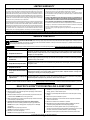
SERVICE CHECKLIST
CONDITION COMMON CAUSES
A. Pump will not start or run.
Check fuse, low voltage, overload open, open or incorrect wiring, open switch, impeller or seal bound mechanically,
defective capacitor or relay when used, motor or wiring shorted. Float assembly held down. Switch defective,
damaged, or out of adjustment.
B. Motor overheats and trips overload
or blows fuse.
Incorrect voltage, negative head (discharge open lower than normal) impeller or seal bound mechanically, defective
capacitor or relay, motor shorted.
C. Pump starts and stops too often. Float tight on rod, check valve stuck or none installed in long distance line, overload open, level switch(s) defective,
sump pit too small.
D. Pump will not shut off. Debris under oat assembly, oat or oat rod bound by pit sides or other, switch out of adjustment.
E. Pump operates but delivers little or
no water.
Check strainer housing, discharge pipe, or if check valve is used vent hole must be clear. Discharge head
exceeds pump capacity. Low or incorrect voltage. Incorrect motor rotation. Capacitor defective. Incoming water
containing air or causing air to enter pumping chamber.
F. Drop in head and/or capacity after
a period of use.
Increased pipe friction, clogged line or check valve. Abrasive material and adverse chemicals could possibly
deteriorate impeller and pump housing. Check line. Remove base and inspect.
In those instances where damages are incurred as a result of an alleged pump failure, the homeowner must retain possession of the pump for investigation purposes.
EASY DO’S & DON'T’S FOR INSTALLING A SUMP PUMP
1. DO read thoroughly all installation material provided with the pump.
2. DO inspect pump for any visible damage caused by shipping. Contact dealer if
pump appears to be damaged.
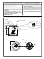
3. DO clean all debris from the sump. Be sure that the pump will have a hard, at
surface beneath it. DO NOT install on sand, gravel or dirt.
4. DO be sure that the sump is large enough to allow proper clearance for the level
control switch(es) to operate properly.
5. DO Always Disconnect Pump From Power Source Before Handling.
DO always connect to a separately protected and properly grounded circuit.
DO NOT ever cut, splice, or damage power cord (Only splice in a watertight
junction box).
DO NOT carry or lift pump by its power cord.
DO NOT use an extension cord with a sump pump.
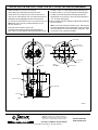
6. DO install a union in the discharge line.
DO NOT use a discharge pipe smaller than the pump discharge.
7. DO NOT use a sump pump as a trench or excavation pump, or for pumping
sewage, gasoline, or other hazardous liquids.
8. DO test pump immediately after installation to be sure that the system is working
properly.
9. DO cover sump with an adequate sump cover.
10. DO review all applicable local and national codes and verify that the installation
conforms to each of them.
11. DO consult manufacturer for clarications or questions.
12. DO
consider a two pump system with an alarm where an installation may become
overloaded or primary pump failure would result in property damages.
13. DO consider a D.C. Backup System where a sump or dewatering pump is
necessary for the prevention of property damages from ooding due to A.C. power
disruptions, mechanical or electrical problems or system overloading.
14. DO inspect and test system for proper operations at least every three months.
3
© Copyright 2012 Zoeller Co. All rights reserved.
1. With basin installed in oor, remove cover from basin.
2. Remove pump with backup pump from carton.
3. Thread all power cords through cord hole in cover and insert cords in
3-hole cord seal. Place lubricant on O.D. of cord seal and insert into
cover. (See Fig. 1)
NOTE: Adjust cords as necessary to eliminate interference of cords with
oats, switches, etc.
4. Assemble PVC pipe reducer and 2" diameter pipe x 3" lg. by solvent
welding (PVC glue). Assemble reducer to pump discharge, per Detail "A".
5. Place pump/backup system in basin oriented per Fig. 2.
NOTE: Pump sits inside of stops.
6. Assemble cover to basin making sure that discharge pipe slips into collar
on bottom of cover. Attach vent and discharge pipe using 2" NPT holes in
cover. Use full-size discharge pipe.
NOTE: Cover must be oriented per instructions (Fig. 3). Basin must be in
accordance with applicable codes and specications. Pump must be level
and oat mechanisms clear of sides of basin before starting pump. Basin
must be clean and free of debris after installation.
7. Refer to Installation Instructions FM2562 for additional details pertaining to
the "Pro Pak" System.
INSTALLATION INSTRUCTIONS FOR 24 X 24 SIMPLEX BASIN ASSEMBLY
26 1/2”
25 5/8
8
(REF)
28
25
(8) .25-20 X 1.25"LG HEX HEAD SCREWS/SS
TIGHTEN BOLTS APPLIED TORQUE 30-40 IN-LBS.
SOLVENT WELD REDUCER TO DISCHARGE PIPE HERE.
2"NPT VENT HOLE
2"NPT DISCHARGE HOLE
2" X 1 1/2" SCH 40
REDUCER (SLIP X SLIP)
2" SCH 40 PVC
PIPE X 3"LG
23° APPROX.
TOP VIEW WITH COVER REMOVED
SIDEVIEW WITH BASIN CUTAWAY
TOP VIEW OF COVER
4" INLET
DISCHARGE
3 HOLE CORD SEAL
DO NOT GLUE HERE (SLIP FIT IN COVER)
SOLVENT
WELD
DETAIL "A"
(SCALE: 2X)
SK2915
Fig. 1
Fig. 2 Fig. 3
MUST ALIGN
SEE NOTE 5 & 6
SEE NOTE 5
SEE NOTE 4
SEE NOTE 3
4
© Copyright 2012 Zoeller Co. All rights reserved.
SK2921
1. With basin installed in oor, remove cover from basin.
2. Remove M53 pump and M53 with backup pump from cartons.
3. Thread all power cords through cord hole in cover and insert cords in
3-hole cord seal. Place lubricant on O.D. of cord seal and insert into cover.
4. Put M53 pump cord through appropriate cord hole in cover and insert cord
in 1 hole cord seal. Place lubricant on O.D. of cord seal and insert in cover.
NOTE: Adjust cords as necessary to eliminate interference of cords
with oats, switches, etc.
5. Place pumps in basin oriented as shown in Fig. 2.
6. Assemble PVC pipe coupling to the backup pump discharge pipe and
insert 1.5" pipe x 15" long in coupling by solvent welding (PVC glue). See Fig. 1.
7. Assemble 1.5" MPT x 1.5" socket adapter to M53 pump discharge (Fig.1).
8. Assemble PVC pipe (1.5" x 32" long) in adapter by solvent welding (Fig.1).
9. Assemble cover to basin making sure that discharge pipes align with
appropriate holes in cover. See Fig. 3. Attach vent using 3" NPT ange on
cover. Use full-size discharge pipe.
10. Refer to Installation Instructions FM2562 for additional details pertaining to
the "Pro Pak" System.
NOTE: Cover must be oriented per instructions (Fig. 3). Basin must be in
accordance with applicable codes and specications. Pump must be level
and oat mechanisms clear of sides of basin before starting pump. Basin
must be clean and free of debris after installation.
INSTALLATION INSTRUCTIONS FOR 24 X 30 DUPLEX BASIN ASSEMBLY
10 1/2
30
1 1/2 DISCHARGE
(2) PLACES
2 1/2 HOLE FOR
3-HOLE CORD SEAL
2 1/2 HOLE FOR
1-HOLE CORD SEAL
3" VENT FLANGE
INSPECTION HOLE
FIG. 3
24" COVER
FIG. 1
FIG. 2
APPROX.
30°
PUMP STAND
SOLVENT WELD HERE
SOLVENT WELD HERE
4" INLET HUB
MAIL TO: P.O. BOX 16347 • Louisville, KY 40256-0347
SHIP TO: 3649 Cane Run Road • Louisville, KY 40211-1961
(502) 778-2731 • 1 (800) 928-PUMP • FAX (502) 774-3624
Your Peace of Mind is Our Top Priority
®
®visit our web site:
www.zoeller.com
  • Page 1 1
  • Page 2 2
  • Page 3 3
  • Page 4 4

Zoeller Pump Co 900-0002 Installation guide

Type
Installation guide

Zoeller Pump Co 900-0002 is an advanced prepackaged system designed for effluent and dewatering applications. This model combines a 24" x 30" duplex basin assembly with the M53 grinder pump and Pro Pak backup system to provide reliable and efficient wastewater handling. The M53 grinder pump effectively macerates solids, preventing clogging and ensuring smooth operation. The Pro Pak backup system adds an extra layer of protection against pump failure or power outages, ensuring uninterrupted wastewater removal.

Ask a question and I''ll find the answer in the document

Finding information in a document is now easier with AI