Page is loading ...

DR
A
F
T
3
/
29
/
2
0
10
INSTALLER: Leave this manual with the appliance.
CONSUMER: Retain this manual for future reference.
INSTALLATEUR
: Laissez cette notice avec l'appareil.
CONSOMMATEUR
: Conservez cette notice pour consul-
tation ultérieure.
- Do not store or use gasoline or other flammable vapors and
liquids in the vicinity of this or any other appliance.
- WHAT TO DO IF YOU SMELL GAS
• Do not try to light any appliance.
• Do not touch any electrical switch; do not use any
phone in your building.
• Immediately call your gas supplier from a neighbor’s
phone. Follow the gas supplier’s instructions.
• If you cannot reach your gas supplier, call the fire
department.
- Installation and service must be performed by a quali
-
fied installer, service agency or the gas supplier.
WARNING: If the information in these instructions is
not followed exactly, a fire or explosion may result
causing property damage, personal injury or death.
- Ne pas entreposer ni utilizer d’essence ni d’autres
vapeurs ou liquides inflammables dans le voisinage
de cet appareil ou de tout autre appareil.
- QUE FAIRE SI VOUS SENTEZ UNE ODEUR DE GAZ:
• Ne pas tenter d’allumer d’appareil.
• Ne touchez à aucan interrupteur. Ne pas vous servir
des téléphones se trouvant dans le bâtiment où vous
trouvez.
• Appelez immédiatement votre fournisseur de gaz
depuis un voisin. Suivez les instructions du fournis-
seur.
• Si vous ne pouvez rejoindre le fournisseur de gaz,
appelez le service des incindie.
- L’installation et l’entretien doivent être assurés par un
installateur ou un service d’entretien qualifié ou par
le fournisseur de gaz.
AVERTISSEMENT: Assurez-vous de bien suivre les
instructions données dans cette notice pour réduire
au minimum le risque d’incindie ou d’explosion ou
pour éviter tout dommage matériel, toute blessure
ou la mort.
INSTALLATION AND OPERATION
Ce manuel d’installation est disponible en francais, s implement en faire
la demande. Numéro de la pièce 850,050CF.
MODELS
OTL Report No. 050-F-22-5
US
Portland
DIRECT-VENT GAS FIREPLACE HEATER INSERTS
P/N 850,050M REV. D 03/2010
Direct-Vent
SHORELINE™
This appliance may be installed in an aftermarket permanently located, manufactured home (USA only) or mobile
home, where not prohibited by local codes. This appliance is only for use with the type of gas indicated on the rating
plate. This appliance is not convertible for use with other gases, unless a certified kit is used.
WARNING
AVERTISSEMENT
TM
SHRL 33/40 DV INS
The Shoreline™ fireplace insert is factory equipped for 40,000 BTU
input and can be converted to 33,000 using the smaller orifice provided.
UNE SURFACE VITRÉE CHAUDE PEUT
CAUSER DES BRÛLURES.
LAISSER REFROIDIR LA SURFACE
VITRÉE AVANT D'Y TOUCHER.
NE PERMETTEZ JAMAIS À UN ENFANT
DE TOUCHER LA SURFACE VITRÉE.
HOT GLASS WILL
CAUSE BURNS.
DO NOT TOUCH GLASS
UNTIL COOLED.
NEVER ALLOW CHILDREN TO
TOUCH GLASS.

2
CONGRATULATIONS!
When you purchased your new gas fireplace insert, you joined
the ranks of thousands of individuals whose answer to their home
heating needs reflects their concern for aesthetics, efficiency
and our environment. We extend our continued support to help
you achieve the maximum benefit and enjoyment available from
your new gas fireplace insert.
Thank you for selecting a Lennox Hearth Products gas fireplace
insert as the answer to your home heating needs.
TABLE OF CONTENTS
Packaging List ...................................................................Page 2
Using this Manual ............................................................. Page 2
Introduction ...................................................................... Page 2
Safety and Warning Information ....................................... Page 3
General Information .......................................................... Page 5
Smoke Detectors ...............................................................Page 6
Codes and Approvals ........................................................ Page 6
New York City MEA Approval ............................................ Page 7
Requirements for the
Commonwealth of Massachusetts ............................... Page 7
Specifications - Insert Dimensions ...................................Page 8
Clearances to Combustibles .............................................. Page 9
Installation ........................................................................ Page 10
Fireplace Requirements ............................................... Page 10
Venting Requirements ................................................. Page 11
Insert Leveling ............................................................. Page 12
Door Assembly Installation
or Removal Instructions .......................................... Page 13
Refractory Brick Panel Installation Instructions ........... Page 14
Log Set Installation Instructions .................................. Page 15
Surround Installation Instructions ............................... Page 17
Gas Line Installation ..........................................................Page 19
Gas Pressure Requirements ........................................ Page 19
LP and Natural Gas Supplies ....................................... Page 19
Attaching Safety In Operation Warnings ........................... Page 20
Operating Instructions ...................................................... Page 21
Pre-Lighting Checklist .................................................Page 21
Lighting Instructions ...................................................Page 21
To Turn Gas Off to Appliance ....................................... Page 22
Shutdown Procedure ................................................... Page 22
Flame Appearance and Sooting ...................................Page 23
Air Shutter Adjustment ................................................ Page 23
Burn-In Period ............................................................. Page 24
Quiet Operation ............................................................ Page 24
Blower Operation and Wiring Diagram ........................Page 24
Shoreline™ Main Burner Operation .............................. Page 25
Millivolt Control System and Wiring Diagram .............. Page 25
Maintenance and Servicing ............................................... Page 26
Maintenance Checklist ................................................. Page 26
Blower Removal ...........................................................Page 26
Glass Maintenance ....................................................... Page 27
Door Removal .............................................................. Page 27
Paint Touch-Up ............................................................ Page 27
Inspecting Wiring ........................................................ Page 27
Fuel Conversion Kits .................................................... Page 27
Maintenance Schedule ................................................. Page 28
Troubleshooting ................................................................ Page 29
Replacement Parts List. .................................................... Page 30
Part Identification .............................................................. Page 31
Optional Accessories ......................................................... Page 36
Safety / Listing Label .........................................................Page 39
Lighting Instructions Label ............................................... Page 40
Warranty and Product Reference Information ................... Page 42
PACKAGING LIST
To install a Shoreline insert, an insert body, refractory brick panel set
and surround kit are required (each sold separately. See Page 37 for
ordering information).
Fireplace Insert Body Packaging List
Model: Shoreline 33/40 DV INS
1) Fireplace Insert Body ...................... 1) 150 cfm Blower
with Burner Cassette
...................... 1) 5-Piece Log Set
1) Gas pipe (3/8” x 8”) ........................ 1) Optional Shoreline #33 orifice
1) Installation and Operation Manual .. 1) Bag of Decorative Lava Rock
1) Bag of Glowing Ember Material ...... 1) Fireplace Warning Label
1) Front Leveling Leg Kit
Refractory Brick Panel Sets - 6 pieces:
Standard
Red
Architectural Stone
Surround Kits:
Small 3-sided - 36-5/8” Wide x 25-7/8” High (930 mm x 657 mm)
Large 3-sided - 41” Wide x 28” High (1041 mm x 711 mm)
Small 4-sided - 36-5/8” Wide x 29-3/16” High (930 mm x 741 mm)
Large 4-sided - 41” Wide x 33-1/2” High (1041 mm x 851 mm)
INTRODUCTION
The Insert models covered in this manual are direct-vent sealed com-
bustion gas heaters designed for residential application for installation
into an existing masonry or factory built solid fuel burning fireplace. The
required liners for the air intake and exhaust are as follows:
• Air Intake: Use 3” diameter UL 181 or UL 1777 listed liner only.
• Exhaust: Use 3” diameter UL 1777 listed gas vent liner only. DO
NOT USE UL 181 LISTED LINER.
This appliance is suitable for installation into masonry or factory built
fireplaces.
These vent systems must be routed through the existing fireplace flue
system to the vent termination.
Installation Options
• .Residential • Manufactured (mobile) home
• .Bedrooms • Commercial
Your direct-vent Insert is designed to be vented vertically with a minimum
height of 10 feet and maximum of 35 feet from top of the flue collar using
natural gas or propane gas (LP).
USING THIS MANUAL
Please read and carefully follow all of the instructions found in this
manual. Please pay special attention to the safety instructions provided
in this manual.
PRODUCT IS SUBJECT TO CHANGE WITHOUT NOTICE

3
IMPORTANT SAFETY AND WARNING
INFORMATION
WARNING
Young children should be carefully supervised when
they are in the same room as the appliance. Tod-
dlers, young children and others may be susceptible
to accidental contact burns. A physical barrier is
recommended if there are at risk individuals in the
house. To restrict access to a fireplace or stove,
install an adjustable safety gate to keep toddlers,
young children and other at risk individuals out of
the room and away from hot surfaces.
AVERTISSEMENT
Les jeunes enfants devraient être surveillés étroite-
ment lorsqu’ils se trouvent dans la même pièce que
l’appareil. Les tout petits, les jeunes enfants ou les
adultes peuvent subir des brûlures s’ils viennent en
contact avec la surface chaude. Il est recommandé
d’installer une barrière physique si des personnes à
risques habitent la maison. Pour empêcher l’accès
à un foyer ou à un poêle, installez une barrière de
sécurité; cette mesure empêchera les tout petits,
les jeunes enfants et toute autre personne à risque
d’avoir accès à la pièce et aux surfaces chaudes.
WARNING
Improper installation, adjustment, alteration, ser-
vice or maintenance can cause injury or property
damage. Refer to this manual. For assistance or
additional information consult a qualified installer,
service agency or the gas supplier.
WARNING
Failure to comply with these installation instructions
will result in an improperly installed and operating
appliance, voiding its warranty. Any change to this
appliance and/or its operating controls is danger-
ous.
WARNING
Clothing or other flammable material should not
be placed on or near the appliance.
AVERTISSEMENT
On ne devrait pas placer de vêtements ni d’autres
matières inflammables sur l’appareil ni à prox-
imité.
WARNING
Any safety screen or guard removed for servicing
the appliance must be replaced prior to operating
the appliance.
AVERTISSEMENT
Tout écran ou protecteur retiré pour permettre
l’entretien de l’appareil doit être remis en place
avant de mettre l’appareil en marche.
WARNING
Improper installation or use of this appliance can
cause serious injury or death from fire, burns,
explosion or carbon monoxide poisoning.
WARNING
Children and adults should be alerted to the hazards
of high surface temperature and should stay away to
avoid burns or clothing ignition.
AVERTISSEMENT
Les enfants et les adultes devraient être infor-més
des dangers que posent les températures de surface
élevées et se tenir à distance afin d’éviter des brûlures
ou que leurs vêtements ne s’enflamment.
WARNING
DO NOT ATTEMPT TO ALTER OR MODIFY THE CON-
STRUCTION OF THE APPLIANCE OR ITS COMPO-
NENTS. ANY MODIFICATION OR ALTERATION MAY
VOID THE WARRANTY, CERTIFICATION AND LISTINGS
OF THIS UNIT.

4
FOR YOUR SAFETY do not install or operate this appliance without
first reading and understanding this manual. Any installation or
operation of the appliance deviating from that which is stated
in this manual WILL void the warranty and may be hazardous.
INSTALLATION AND REPAIR SHOULD ONLY BE DONE BY
A QUALIFIED SERVICE TECHNICIAN. DO NOT ATTEMPT
TO SERVICE THE APPLIANCE YOURSELF.
Do not make any make-shift compromises during installation.
Any modification or alteration may result in damage to the
appliance or dwelling and will void the warranty, certification
and listings of this unit.
Failure to use manufacturer provided parts, variations in tech-
niques and construction materials or practices other than those
described in this manual may create a fire hazard and void the
limited warranty.
This gas appliance must be equipped for the proper fuel type
and altitude at which it will be operated. Any operation outside
the parameters outlined in this manual may result in a hazard-
ous condition and will void the warranty. Please carefully read
the sections pertaining to these subjects and/or be sure your
appliance is properly equipped.
Never use solid fuels such as wood, paper, cardboard, coal, or
any flammable liquids, etc., in this appliance.
Any grill, panel, or glass removed for service MUST be replaced
prior to operating the appliance. Do not operate appliance with
the glass front removed, cracked or broken.
Gold and nickel plated surfaces must be cleaned with glass
cleaner and a clean soft cloth before firing the first time or
fingerprints will remain permanently. NEVER use brass polish
to clean gold or nickel, this will remove the plating!!!
When opening the lower door on the face while the appliance is
burning, pull at the far left or far right vent openings, because
the door is hot during operation.
LHP, its employees, or any of its representatives assume no
responsibility for any damages caused by an inoperable, inad-
equate, or unsafe condition as a result of any improper operation,
service or installation procedures, whether direct or indirect.
Due to high temperatures, the appliance should be located out
of traffic and away from furniture and draperies.
En raison des températures élevées, l’appareil devrait être
installé dans un endroit où il y a peu de circulation et loin du
mobilier et des tentures.
Provide adequate clearances around air openings and adequate
accessibility clearance for service and proper operation. Never
obstruct the front openings of the appliance.
These appliances are designed to operate on natural or propane
gas only. The use of other fuels or combination of fuels will
degrade the performance of this system and may be danger-
ous.
These appliances are designed as supplemental heaters. There-
fore, it is advisable to have an alternate primary heat source
when installed in a dwelling.
These appliances must not be connected to a chimney or flue
serving a separate solid fuel burning appliance.
These appliances are vented gas appliances. Do not burn wood
or other material in these appliances.
This appliance is only for use with the type of gas indicated on
rating plate. This appliance is not convertible for use with other
gases, unless a certified kit is used.
Cet appareil doit être utilisé uniquement avec les types de gaz
indiqués sur la plaque signalétique. Ne pas l'utiliser avec
d'autres gaz sauf si un kit de conversion certifié est installé.
Hot while in operation. Do not touch. Severe Burns may result.
Keep children, clothing furniture, gasoline and other liquids
having flammable vapors away.
L’appareil est chaud lorsqu’il fonctionne. Ne pas toucher
l’appareil. Risque de brûlures graves. Surveiller les enfants.
Garder les vêtements, les meubles, l’essence ou autres liquides
produisant des vapeur inflammables loin de l’appareil.
This appliance may be installed in an aftermarket, permanently
located, manufactured home (USA only) or mobile home, where
not prohibited by local codes.
Cet appareil peut être installé dans une maison préfabriquée
(mobile) déjà installée à demeure si les règlements locaux le
permettent.
Ensure clearances are in accordance with local installation
codes and the requirements of the gas supplier.
Dégagement conforme aux codes d'installation locaux et aux
exigences du foumisseunde gaz.
Installation and repair should be done by a qualified service
person. The appliance should be inspected before use and at
least annually by a professional service person. More frequent
cleaning may be required due to excessive lint from carpet-
ing, bedding material, etcetera. It is imperative that control
compartments, burners and circulating air passageways of the
appliance be kept clean.
L’installation et la réparation devrait être confiées à un technicien
qualifié. L’appareil devrait faire l’objet d’une inspection par un
technicien professionnel avant d’être utilisé et au moins une
fois l’an par la suite. Des nettoyages plus fréquents peuvent
être nécessaires si les tapis, la literie, et cetera produisent une
quantité importante de pous-sière. Il est essentiel que les com-
partiments abritant les commandes, les brûleurs et les conduits
de circulation d’air de l’appareil soient tenus propres.
Do not use these appliances if any part has been under water.
Immediately call a qualified, professional service technician
to inspect the appliance and to replace any parts of the control
system and any gas control which have been under water.
Ne pas utiliser cet appareil s’il a été plongé, même partielle-
ment, dans l’eau. Appeler un technicien qualifié pour inspecter
l’appareil et remplacer toute partie du système de commande
et toute commande qui a été plongée dans l’eau.
Only trim kit(s) supplied by the manufacturer shall be used in
the installation of this appliance.
Seules les trousses de garniture fournies par le fabricant doivent
être utilisées pour l’installation de cet appareil.
INSTALLER: THESE INSTRUCTIONS ARE TO REMAIN WITH THE
HOME OWNER!

5
NOTE: DIAGRAMS AND ILLUSTRATIONS ARE NOT TO SCALE
Millivolt Models with Manually-Modulated Gas Valves
Natural Gas Propane (LP) Gas
Model Input Rate
(BTU/HR)
Input Rate
(BTU/HR)
SHR33 19,500 to 33,000 19,500 to 33,000
SHR40 24,000-40,000 21,500 to 37,500
Table 1
These appliances may be installed in an aftermarket permanently
located, manufactured home (USA only) or mobile home, where not
prohibited by local codes.
Cet appareil peut être installé dans un maison préfabriquée (É.-U.
seulement) ou mobile déjà installée à demeure si les réglements
locaux le permettent.
Table 2 shows efficiencies for the Shoreline™.
GENERAL INFORMATION
Table 1 shows the BTU input for each model:
Note: These appliances are designed as supplemental heaters. There-
fore, it is advisable to have an alternate heat source when installed in a
dwelling.
Millivolt Valve & Electrical
These appliances use a millivolt type control system consisting of a gas
control valve with regulator (control to adjust for flame appearance and heat
output), a standing pilot burner assembly, a thermopile, thermocouple, a
piezo igniter, and ON/OFF switch. THE GAS BURNER SYSTEM ON THESE
APPLIANCES DO NOT REQUIRE 120 VOLT POWER TO OPERATE. Because
this fireplace insert is operated with a millivolt valve it will burn even
during a power outage.
The Shoreline features a spark igniter (piezo) that allows the appliance's
pilot gas to be lit without the use of matches or batteries. However, the heat
circulation blower motor requires 120 Volts AC (the appliance can be safely
used with the blower turned off). The blower operation is controlled by a
variable speed rheostat.
Fuel
This insert comes from the factory equipped to burn natural gas from 0
to 2,000 feet (610 M) of elevation in the USA and 0 - 4,500 feet (1372
M) in Canada. The insert can be converted to burn LP (liquid propane)
by installing a conversion kit. Only Lennox Hearth Products conversion
kits can be used to convert from NG to LP or LP to NG. Contact your
Lennox Hearth Products dealer for details. An orifice is also supplied to
change the unit from 40,000 BTU’s (NG) or 37,500 BTU’s (LP) to 33,000
BTU’s. This must be done by a qualified service technician if you decide
to change orifices.
The use of other fuels or combination of fuels will degrade the performance
of this system and may be dangerous.
Orifice Size/Altitude Adjustment
These appliances are tested and approved for installations at elevations
of 0 to 2,000 feet (610 M) in the USA and 0 to 4,500 feet (0-1372 M) in
Canada using the factory installed orifice shown in Table 3. At higher
elevations the BTU input must be de-rated by 4% for every 1,000 feet
(305 M) to maintain the proper ratio of gas to air. Contact your local gas
supplier for deration requirements for your area.
Deration - At higher elevations, the amount of BTU fuel value delivered
must be reduced by either using gas that has been derated by the gas
company or by changing the burner orifice to a smaller size as regulated
by the local authorities having jurisdiction and by the (USA) National
Fuel Gas Code NFPA 54 / ANSI Z223.1 - latest edition or, in Canada,
the CAN/CSA B149.1 - latest edition. If it is determined that a smaller
burner orifice is needed, contact your Lennox Hearth Products dealer to
purchase the orifice.
Burner Orifice Sizes
USA - Elevation 0-2000 feet ( 0-610 meters)
Canada - Elevation 0-4500 feet ( 0-1372 meters)
Model
Natural Gas
drill size (inches) *
Propane
drill size (inches) *
SHR33 #36 (0.1065”) #51 (0.067”)
SHR40 1/8” (0.125”) #49 (.073”)
Table 3 * Standard size installed at factory
Efficiencies %
Natural Gas Propane
Models P4** Steady
State*
AFUE P4** Steady
State*
AFUE
SHR33 60.91 83 60 64.35 83 65
SHR40 62.70 83 63 65.98 83 67
* The Steady State Efficiency numbers based on maximum vent configuration.
** Tested to CSA P.4.1-02 “Testing Method for Measuring Annual Fireplace Efficiency.
Table 2
This appliance is only for use with the type of gas indicated on the
rating plate. This appliance is not convertible for use with other gases,
unless a certified kit is used.
Cet appareil doit être utilisé uniquement avec les types de gaz indiqués
sur la plaque signalétique. Ne pas l'utiliser avec d'autres gaz sauf si
un kit de conversion certifié est installé.
These appliances comply with National Safety Standards and are tested
and listed by OMNI-Test Laboratories Inc.; Portland, Oregon (Report No.
050-F-22-5) to ANSI Z21.88-2005/CSA 2.33-2005, and CGA 2.17-M91 in
both USA and Canada, as Vented Gas Fireplace Heaters and are approved
for installation in bedrooms and manufactured (mobile) homes.

6
NOTE: DIAGRAMS AND ILLUSTRATIONS ARE NOT TO SCALE
CODES AND APPROVALS
Listing and Safety Standards - Gas appliances must be tested and certi-
fied by a nationally recognized testing and certification laboratory to ANSI
(American National Standard Institute) gas appliance safety standards.
This insert has been tested and certified by OMNI -Test Laboratories to
ANSI Z21.88/CSA 2.33 “Vented Gas Fireplace Heaters and CGA 2.17-
M91 “Gas-Fired Appliances for Use at High Altitudes” and UL 307B Gas
Burning Heating Appliances for Manufactured (Mobile) Homes in both
USA and Canada. These appliances have been certified for use with
either natural gas or propane and are approved for installation in sitting
rooms and/or bedrooms. This appliance is only for use with the type of
gas indicated on the rating plate (and is not for use with solid fuels).
This appliance is not convertible for use with other gases, unless a
certified kit is used.
Cet appareil doit être utilisé uniquement avec les types de gaz indiqués
sur la plaque signalétique. Ne pas l'utiliser avec d'autres gaz sauf si
un kit de conversion certifié est installé.
Manufactured Home Installations - These appliances must conform
to the Manufactured Home Construction and Safety Standard, Title 24
CFR, Part 3280 (in Canada CAN/CSA Z240 MH) (in Canada CAN/CSA
Z240 MH), or when such a standard is not applicable, the Standard
for Manufactured Home Installations, ANSI A225.1 - latest edition for
manufactured (mobile) home installations and the current Standard for
Fire Safety Criteria for Manufactured Home Installations, Sites and Com-
munities, ANSI/NFPA 501A.
Local, State and National Codes - These appliances must conform with
all local, state, and national installation codes. In the absence of local
and state codes, installation must comply with the current National Fuel
Gas Code, ANSI Z223.1, also known as NFPA 54 (In Canada, the current
CAN/CSA B149.1 installation code). Electrical wiring must comply with
the National Electrical Code ANSI/ NFPA 70 - latest edition. In Canada, the
current CSA C22-1 Canadian Electrical Code - latest edition. Refer to the
National Fuel Gas Code and local zoning and code authorities for details
on installation requirements. These appliances must be vented directly
to the outside in accordance with the current edition of the National Fuel
Gas Code (NFPA 54 in U.S.A and CAN/CSA B149.1 in Canada) and must
never be attached to a chimney serving a separate solid fuel burning
appliance.
Fireplace Standards - These heaters are designed to be installed into
an existing masonry fireplace (built to UBC 37 or ULC S628 standards)
or factory built solid fuel, wood, burning fireplace (listed to UL 127 or
ULC S610) only. All exhaust gases must be vented outside the structure.
Combustion air is drawn from outside the structure.
Questions To Ask Local Building Official
These appliances must be installed per manufacturers’ instructions.
Installations must conform to appropriate local codes and applicable
state and federal requirements. Familiarity with these requirements
before installation is essential. Some important considerations to
discuss with local building officials include:
1. Applicable codes (i.e. Uniform Mechanical Code, State or Regional
Gas Codes, National Fuel Gas Code).
2. Local amendments
3. Recognized testing lab: OMNI-Test Laboratories Inc.; Portland,
Oregon
4. Is a permit required - cost?
5. In some states or municipalities, a licensed gas fitter or plumber may
be required to install these appliances. Check with your local build-
ing official for requirements in your area (i.e. Is a license required for
installation of gas supply line)?
6. Maximum amount of gas pipe without a pressure test - type of test
required?
7. Are below grade penetrations of the gas line allowed?
8. Is concealed gas piping allowed?
9. Specific requirements of concealed fittings?
10. Is rigid pipe to appliance required?
11. Allowed piping materials?
12. Shut-off valve required within 4 feet of the firebox?
13. May the shut-off valve be concealed?
14. Rooms where the installation is not allowed?
SMOKE DETECTORS
Since there are always several potential sources of fire in any home, we
recommend installing smoke detectors. If possible, install the smoke
detector in a hallway adjacent to the room (to reduce the possibility of
occasional false activation from the heat produced by the appliance). If
your local code requires a smoke detector be installed within the same
room, you must follow the requirements of your local code. Check with
your local building department for requirements in your area.

7
NOTE: DIAGRAMS AND ILLUSTRATIONS ARE NOT TO SCALE
NEW YORK CITY, NEW YORK (MEA)
(NYC MEA Approval #138-07-E)
Installation of these appliances are approved for installation in New York
City in the US state of New York.
COMMONWEALTH OF MASSACHUSETTS REQUIREMENTS
(Massachusetts Approval #G3-0508-369)
These appliances are approved for installation in the US state of Mas-
sachusetts if the following additional requirements are met:
•
Install this appliance in accordance with Massachusetts Rules and
Regulations 248 C.M.R.
• Installation and repair must be done by a plumber or gas fitter licensed
in the Commonwealth of Massachusetts.
• The flexible gas line connector used shall not exceed 36 inches (92
centimeters) in length.
• The individual manual shut-off must be a T-handle type valve.
Massachusetts Horizontal Vent Requirements
In the Commonwealth of Massachusetts, horizontal terminations installed
less than seven (7) feet above the finished grade must comply with the
following additional requirements:
• A hard wired carbon monoxide detector with an alarm and battery
back-up must be installed on the floor level where the gas fireplace
is installed. The carbon monoxide detector must comply with NFPA
720, be ANSI/UL 2034 listed and be ISA certified.
• A metal or plastic identification plate must be permanently mounted to
the exterior of the building at a minimum height of eight (8) feet above
grade and be directly in line with the horizontal termination. The sign
must read, in print size no less than one-half (1/2) inch in size, GAS
VENT DIRECTLY BELOW. KEEP CLEAR OF ALL OBSTRUCTIONS.

8
NOTE: DIAGRAMS AND ILLUSTRATIONS ARE NOT TO SCALE
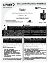
Figure 1
Front View
Side View
Top View
Insert Dimensions Inches (millimeters)
A
Left front of unit to center line 13-1/8 (333)
B
Right front of unit to center line 17-1/4 (438)
C
Left rear of unit to center line 9 (229)
D
Right Rear Of Unit To Center Line 7-5/8 (194)
E
Center Of Air Intake To Center Line 6-3/4 (172)
F
Center Of Flue To Center Line 2 (51)
G
Insert Depth Into Fireplace 15-3/8 (391)
H
Air Intake Center From Front 12-7/8 (327)
I
Flue Center From Front Of Unit 14 (356)
J
Front Of Unit To Back Of Flue Collar 15-1/8 (384)
K
Unit Height At Front 22-3/8 (568)
L
Base Of Unit To Top Of Flue Collar 21 (533)
M
Base Of Unit To Intake Collar 7-7/8 (200)
N
O.D. Width, Small, 3-pc Flange 36-5/8 (930)
N
O.D. Width, Large, 3-pc Flange 41 (1041)
O
O.D. Height, Small, 3-pc Flange 25-7/8 (657)
O
O.D. Height, Large, 3-pc Flange 28 (711)
P
O.D. Width, Small, 4-pc Flange 36-5/8 (930)
P
O.D. Width, Large, 4-pc Flange 41 (1041)
Q
O.D. Height, Small, 4-pc Flange 29-3/16 (741)
Q
O.D. Height, Large, 4-pc Flange 33-1/2 (851)
R Glass Viewing Height 16-7/8 (429)
S Glass Viewing Width 26-5/8 (676)
Note: Due to Lennox’ ongoing commitment to quality , all specifications,
ratings and dimensions are subject to change without notice.
Rear Insert Dimensions - Inches (millimeters)
Rear width of unit 16-5/8 (422)
Front Width of unit 30-3/8 (772)
Depth of unit (excluding Surround Kit) 15-3/8 (391)
Front View
SPECIFICATIONS: Shoreline™
K
L
M
J
N
R
S
O
P
Q
3-Sided Surround Kit
4-Sided Surround Kit
Center
A
B
C
D
E
F
G
H
I
FLUE
Ø 2-7/8
AIR INTAKE
Ø 2-7/8

NOTE: DIAGRAMS AND ILLUSTRATIONS ARE NOT TO SCALE
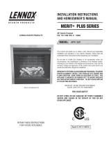
Figure 2 - Existing Fireplace Minimum Dimensions
Minimum Fireplace Dimensions
and Minimum Clearances
Inches
(millimeters)
A Minimum front opening required 36 (914)
B Minimum height required 21-1/2 (546)
C Minimum rear width required 19-1/2 (495)
D Minimum fireplace depth required 16 (406)
E Clearance needed from bottom of insert to com-
bustibles or 8” mantel
35 (889)
F Clearance required from center of glass to com-
bustible material
30 (762)
G Minimum inches of hearth protection needed from
front of unit
12 (305)
H Vertical clearance needed under the bottom of the
insert for NO hearth protection
8 (203)
I Clearance needed from bottom of insert to 12”
mantel
38 (965)
Table 4
Refer to Table 4
Refer to Figures 2 through 4
These appliances can be installed in most fireplace configurations. If
installed close to an adjacent wall, ensure that the minimum clearances
to combustible surfaces are maintained. A local building inspector
should review your plans prior to installation.
Refer to Figures 2 through 4 for clearances to combustibles. Minimum
clearances include any projections such as shelves, window sills, mantels,
spacers/standoffs or surfaces to combustible construction etc. above the
appliance. Paint or lacquer used to finish the mantel must be heat resistant
in order to avoid discoloration.
9
MINIMUM CLEARANCES TO COMBUSTIBLES
Hearth / Floor Protection Requirements
The hearth and/or floor protection must be a thermally rated hearth/floor
protector meeting or exceeding a thermal rating of k = .84 (or lower) or
r= 1.19 (or higher) with a listed thickness of 1" minimum. If an hearth
extension is used, check with the manufacturer for the listed thermal rating
of the hearth extension to ensure it meets the thermal requirements of k
= .84, r= 1.19, listed thickness 1". If a custom hearth or floor protection
is planned, see NFI (National Fireplace Institute) certification manuals
showing methods for calculating minimum thicknesses and approved
fireplace hearth/floor protection materials.
E
F
G
H
I
C
L
Figure 3 - Minimum Clearances
Combustibles Trim or Mantel Depth of 8” or Less
Hearth Protection
Mantel - 12” Depth
Refer to Table 4
Examples:
Hearths that are level with the base
of the insert require 12” minimum of
forward hearth protection.
Hearths that are elevated 8” minimum
above combustible floor require 0” of
forward hearth protection.
G
H
Combustible Floor
Figure 4 - Hearth Protection
G H
H dimension deter-
mines G minimum
0” 8”
1-1/2” 7”
3” 6”
4-1/2” 5”
6” 4”
7-1/2” 3”
9” 2”
10-1/2” 1”
12” 0”
Hearth Protection
Fireplace Firebox
Insert
A
B
C
D

10
NOTE: DIAGRAMS AND ILLUSTRATIONS ARE NOT TO SCALE
WARNING
THIS FIREPLACE HAS BEEN ALTERED TO
ACCOMMODATE A FIREPLACE INSERT AND
SHOULD BE INSPECTED BY A QUALIFIED
PERSON PRIOR TO RE-USE AS A
CONVENTIONAL FIREPLACE.
Fireplace Requirements
These heaters are designed to be installed into an existing masonry
fireplace (built to UBC 37 or ULC S628 standards) or factory built solid
fuel, wood burning fireplace (listed to UL 127 or ULC S610) only. All
exhaust gases must be vented outside the structure. Combustion air
is drawn from outside the structure. When installing in a factory built
fireplace, the fireplace grate must be removed and the damper must be
removed or secured open.
The insert is designed to fit into a fireplace with a minimum firebox
height of 21-1/2 inches (546 mm). To facilitate this the hood will need to
be removed and discarded (Note: the screws should be replaced in the
insert body). The air intake on the Shoreline™ is removable for easier
installation.
If the factory-built fireplace has no gas access hole(s) provided, an access
hole of 1-1/2 inches (38 mm) or less may be drilled through the lower
sides or bottom of the firebox in a proper workmanship like manner. This
access hole must be plugged with a non-combustible insulation after the
gas supply line has been installed. The installer must mechanically attach
the marking supplied with the gas fireplace insert to the inside of the firebox
of the fireplace into which the gas fireplace insert is installed.
Si le foyer préfabriqué ne comporte pas d’orifices d’amenée du gaz, un
orifice d’au plus 37,5 mm (1,5 po) peut être pratiqué, selon les règles
de l’art, dans la partie inférieure des parois ou au fond de la chambre de
combustion. Cet orifice doit être obturé au moyen d’isolant incombustible
une fois la conduite de gaz en place.
IMPORTANT: When installing these appliances into a factory built fireplace
or heat-form, the air flow within and around the fireplace shall not be
altered by the installation of the insert (i.e. DO NOT BLOCK louvers or
cooling air inlet or outlet ports, circulating air chambers in a steel fireplace
liner or metal heat circulator).
CAUTIONS
• Trim panels or surrounds must not seal ventila-
tion openings in the existing fireplace that the
appliance is installed in.
• The fireplace in which this gas insert is to be
installed must be thoroughly cleaned if it has
been used to burn wood or synthetic logs. Have
the chimney and all inside surfaces of the fire-
place brushed and vacuumed so that no soot,
embers, or loose combustion deposits can be
drawn into the heat circulation blower and blown
into the living area.
• If any portion of the chimney system shows signs
of structural or mechanical weaknesses, such
as: cracks, leaky joints, corroded or warped
surfaces, the faulty portion must be repaired
or replaced prior to installing this appliance.
• The factory built firebox must accept the insert
without modification other than removing bolted
or screwed together pieces such as baffles /
smoke shelf / deflectors, ash lips, glass door,
screen or door tracks, log grates, refractory or
masonry lining and damper assemblies. Any
fireplace component, which is removed, must be
retained so they can be reinstalled to restore the
fireplace to its original operating condition. The
removal of any part must not alter the integrity
of the outer shell of the pre-engineered fireplace
cabinet in any way. Any parts removed must be
replaceable. If any components are removed
from (or altered) from the existing fireplace, a
Warning Label (see Figure 5) must be affixed
inside the fireplace firebox, so that it shall be
visible upon removal of the fireplace insert. Note:
RTV high temperature silicone is an approved
adhesive to affix the label.
Figure 5 - Fireplace Warning Label
INSTALLATION

11
NOTE: DIAGRAMS AND ILLUSTRATIONS ARE NOT TO SCALE
Venting Requirements
Approved Vent Systems:
Lennox Hearth Products Co-linear Chimney Liner Kit Recommended:
• The Flex Kit, Cat. No. H0909 includes one 35 feet flex liner and four
gear clamps.
• The Termination Kit, Cat. No. TKDVI includes the termination cap with two
co-linear collars for 3 inches (76 mm) flex attachments and flashing.
• The Flex and Termination Kit, Cat. No. DV3FK35 includes two flex liners,
termination cap and four gear clamps.
Secure Vent™ Co-Linear Chimney Liner Kit Recommended:
• Direct-Vent Vertical Termination Kit (includes Vertical Termination
Cap gas/Connector, Flashing, Qty 2 of 25 feet (7.6 M) length of 3 inches
(76 mm) Aluminum Flex, Clamps and Sealant) #DV3FK25
• Direct-Vent Vertical Termination Kit (includes Vertical Termination Cap/
Connector, Flashing, Qty 2 of 35 feet length of 3 inches Aluminum
Flex, Clamps and Sealant) #DV3FK35
Standard Simpson Dura-vent Co-linear Chimney Liner Kit recom-
mended:
• Direct-Vent Vertical Termination Cap #991
• Liner Termination Kit
(includes termination connector and flashing) #923GK
• 3" x 35 feet (76 mm x .91 M) Alum Flex #2280
Selkirk/Metalbestos Direct-Temp Co-Linear Chimney Liner Kit recom-
mended
• Direct-Vent Vertical Termination Cap #4DT-VC
• Liner Termination Kit
(includes termination connector and flashing) #4DT-CTB
• 3” x 35’ (76 mm x .91 M) Aluminum Flex #AF3-35L
Amerivent Direct Co-Linear Chimney Liner Kit recommended
• Direct-Vent Vertical Termination Cap #4DVC
• Co-Linear Adaptor #4DCAT33
• Flashing #4DF or #5DF
• 3” x 35’ Aluminum Flex #3AFL-35
WARNING
Do not substitute the heat-rated flex liner (UL1777) for the
exhaust with any other type liner or a fire may result caus-
ing property damage, personal injury or loss of life.
Positive Flue Connection
Masonry and Factory Built Fireplaces
A qualified installer should evaluate the existing fireplace to determine
the best method for achieving a positive flue connection between the vent
and intake liners and the chimney.
Air Inlet Liner (for combustion air) When
terminating the air inlet liner at this point, a
positive flue connection is required (to ensure
combustion air is drawn down the chimney
only).
Exhaust 3" (75mm) UL
1777. A full length liner
is required from the
exhaust outlet on appli-
ance to center collar of
termination cap.
Positive Flue Con-
nection (sealing
fireplace throat
using a noncombus-
tible seal-off plate
or insulation).
The outside air inlet does not
require a full reline (if intake
liner is terminated in chimney
and a positive flue connection
is achieved as specified).
Air Inlet
Exhaust
Air Inlet
Existing Fireplace Flue
(chimney)
Masonry and Factory Built Fireplaces
Figure 6a - Terminating Air Inlet in Chimney
Vertical Cap
Termination
Connector
Exhaust
Intake
Combustion Air Intake
The existing fireplace chimneys may take
various contours which the flexible liners will
accommodate. However, keep the flexible liner
as STRAIGHT as possible, avoid unnecessary
bending.
Liner Requirements:
Vertical Height Min. = 10 ft. (3.05 M)
Vertical height Max. = 35 ft. (10.67 M)
Use 3" (76 mm) diameter listed gas
vent liner (UL1777 ONLY) for the
EXHAUST
Use 3" (76 mm) diameter listed
liner (UL 181 or UL1777) for the
AIR INTAKE.
The flexible vent pipe
must NOT be allowed to
sag behind insert or in
fireplace flue.
The standard cap
in Termination Kit,
TKDVI, is a high
wind cap
Make sure that both liners will pass through existing damper area. Remove
or lock damper to allow the passage of the flexible liners. If the damper
will not allow the passage of both liners, DO NOT PROCEED FURTHER.
(If fireplace is masonry) Consult a local mason for removal of the damper
without risk of structural damage or leakage (if the fireplace is factory
built) The appliance may NOT be installed into the fireplace.
Figure 6b
NOTE: Terminating the air intake liner as shown here may not be
allowed by some local codes. Check with the authority having jurisdic-
tion for your area.

12
Vertical Venting
The combustion air intake pipe can be connected to the termination cap
(see Figure 6b) or it can terminate inside the chimney (see Figure 6a).
If combustion air intake pipe is terminated inside the chimney and not
connected to the actual termination cap the bottom opening of the chim-
ney (chimney throat) must be sealed around the vent pipes. Use a non
combustible seal-off plate (i.e. 22 gage sheet steel) or unfaced fiberglass
insulation (8 lb per square foot density minimum) to seal around the vent
pipes. Whichever “seal off” method is used must effectively seal the area
to prevent room air passage to the chimney of the fireplace. The insulation
may give off an odor during the first hour of operation.
NOTES:
The minimum vertical rise (exhaust vent) is 10 feet (3.05 M) and the
maximum vertical rise is 35 feet (10.67 M). These dimensions are
measured from the flue collar of the unit to the end of the vent pipe,
The fireplace and fireplace chimney must be clean and in good working
order and constructed of non-combustible materials. Inspect chimney
clean-outs for proper fit and seal.
See Table 5 for the minimum vertical termination height requirements.
� � � � � � � � � � � � � � � � � �
� � � � � � � � � � � � � � � � � �
� � � � � � � � � � � � � � � � � �
� � � � � � � � � � � � � � � � � �
� � � � � � � � � � � � � � � � � �
� � � � � � � � � � � � � � � � � �
� � � � � � � � � � � � � � � � � �
� � � � � � � � � � � � � � � � � �
Vertical Termination Height Minimum
(Factory Built and Masonry Fireplaces)
The vent/air intake termination clearances above the high side of an
angled roof is as follows:
8 (2.4)
7 (2.1)
6 (1.8)
5 (1.5)
4 (1.2)
3 (0.9)
2 (0.6)
1 (0.3)
0 (0.0)
2/12
4/12
6/12
8/12
10/12
12/12
14/12
16/12
Table 5
Feet (meters)
Roof Pitch
Insert Leveling
At each front and rear corner of the insert is an adjustable leg provided
to level the insert should the hearth of the fireplace be uneven. To adjust
the legs in the rear, loosen the two 5/32” allen head screws, move the leg
to the desired height, and then tighten the screws. Repeat these steps
for each adjusting leg. To adjust the legs in the front use a 9/16” open
end wrench. See Figures 7 and 8.
NOTE: The rear leveling legs on each side of the gas fireplace insert unit
have 13/64” holes located in them for the purpose of fastening the rear
of the unit down in the fireplace (masonry or factory built fireplace).
Right front leveling leg. Use open end 9/16”
wrench to adjust height up or down
See Detail A
Figure 7
FRONT
LEVELING
LEGS
Figure 8
Front leveling legs
Detail A
Use 5/32 allen wrench to loosen and adjust
bracket up or down, tighten when at right height
Detail B
See Detail B
REAR
LEVELING
LEGS

13
Tools Needed: 5/32” Allen Wrench or T-Handle
Cat. No. Description
H5746 Shoreline Door Assembly
(Figure 9)
1. Locate the three bottom tabs on the bottom of the door. These tabs
on the bottom of the door will insert in the slots along the bottom of
the insert. See Figure 10.
2. Drop the door into these three slots on the bottom of the insert as
shown in Figure 11. Once this is done you can then rotate the door
up to seal against the firebox front.
3. Using the 5/32” Allen Wrench or T-Handle insert the three 10-24 screws
with washers into the three locations on the upper latch assembly. You
can then tighten the screws down by turning the wrench or T-Handle
clockwise (SNUG ONLY-DO NOT OVERTIGHTEN). See Figure 12.
4.
Figure 13 shows the insert with the door in place.
Figure 9
Figure 10
Figure 11
Figure 12
Figure 13
Shoreline Door Kit - Packaging List
Models SHR33 & SHR40
Quantity Description
1
Shoreline Door Assembly
Table 6 - (refer to Figure 9)
Note: The Shoreline insert comes with the door already on the unit.
Just reverse the steps here to remove the door to access the burner
area.
SHORELINE™ DOOR ASSEMBLY INSTALLATION OR REMOVAL
INSTRUCTIONS
Upper Latch Tabs
Bottom Tabs
See Detail B
Detail B
NOTE: DIAGRAMS AND ILLUSTRATIONS ARE NOT TO SCALE
See Detail E
Detail E
See Detail C
Detail C

14
4. Slide the top panel in place with the detailed side down. Make sure
panel is positioned all way back and resting on side panels. Top panel
should be flush in front with the side panels. See Figure 18.
3. Position and slide the side panels against the rear panel. Make sure
panels are behind brackets to hold them in at the top. The side panels
will hold the rear brick panel against the back of the firebox. See Figure
17.
B
C D
A
2. Next place the rear panel (B). It will set on the bracket mounted to the
blower mounting plate on the back of the firebox. See Figure 16.
To Install Panels:
1. Start with the front bottom panel A. Set the front bottom panel in
place with detail side facing up as shown. See Figure 15.
E
CAUTION
Before you install the refractory brick panels and log
set, the insert should be installed in the fireplace, the
venting attached, the gas line connected and tested
for leaks and the initial burner operation checked.
Figure 15
Figure 16
Figure 17
Figure 18
Refractory Brick Panel Kits - Packaging List
Models SHR33 & SHR40
Quantity Description
1 Front Bottom Panel (A)
1 Rear Panel (B)
1 Left Side Panel (C)
1 Right Side Panel (D)
1 Top Panel (E)
Table 7 - (refer to Figure 14)
Tools Needed: No tools are needed
Cat. No. Model Description
H7987 SHR-BRK-STD Brick Panel Set, Tan
H7988 SHR-BRK-RED Brick Panel Set, Red
H7989 SHR-BRK-ARCHSTONE Brick Panel Set, Architectural (shown)
NOTE: DIAGRAMS AND ILLUSTRATIONS ARE NOT TO SCALE
SHORELINE™ REFRACTORY BRICK INSTALLATION INSTRUCTIONS
IMPORTANT NOTE: A refractory brick panel kit is required for proper
operation (sold separately). Never operate this appliance without
all the refractory brick panels properly installed.
B
A
D
C
E
Figure 14

15
NOTE: DIAGRAMS AND ILLUSTRATIONS ARE NOT TO SCALE
A
C
D
E
F
B
G
A
Log supports
A
B
C
D
E
To Install Log Set:
1. Open the box and carefully remove and identify the different items.
Start with the rear log (A). Set it down on the log supports located
on the left rear of firebox. See Figure 21.
Figure 21
CAUTIONS
•
If logs are not installed according to the log
installation instructions, flame impingement
and improper combustion could occur and result
in soot and/or excessive production of carbon
monoxide (CO), a colorless, orderless, toxic
gas.
•
The size and position of the log set is critical
to achieve a safe, reliable and attractive flame
pattern. Any attempt to use a different log set
in the fireplace will void the warranty and will
result in incomplete combustion, sooting, and
poor flame quality.
Figure 19
Figure 20
Log Set - Packaging List
Models SHR33 & SHR40
Quantity Description
1 Rear Log (A)
1 Center Log (B)
1 Left Log (C)
1 Right Log (D)
1 Front Log (E)
1 Bag of Glowing Embers (F)
1 Bag of Decorative Lava Rock (G)
Table 8 - (refer to Figure 19)
Tools Needed: No tools are needed
Cat. No. Description
H5747 5-Piece Ceramic Log Set
SHORELINE™ LOG SET INSTALLATION INSTRUCTIONS

16
NOTE: DIAGRAMS AND ILLUSTRATIONS ARE NOT TO SCALE
2. Separate the glowing embers (F) into quarter size pieces and place
along ports on burner pan. DO NOT cover burner secondary holes
on burner pan. The pattern for the glowing embers should be similar
to what is shown in Figure 22.
3. Place center log (B) on supports towards bottom left and top right of
log (B). See Figure 23.
4. Place left log (C) on pin in back. Push log against left side of refractory
in front. See Figure 24.
C
B
F
pin
5. Locate groove in center log (B), and place the top of the right log
(D) in groove with the bottom end of the log resting against the right
refractory panel. See Figure 25.
6. Place the front log (E) as shown in
Figure 26, making sure no burner
ports are covered. Place the decorative lava rock around logs as
desired, again making sure there are no ports or holes covered.
E
D
Groove for log (D)
7. Figure 26 shows the complete set of ceramic logs in the correct loca-
tions.
Figure 24
Figure 23
Figure 22
Figure 25
Figure 26
Glowing Embers
Bag of Glowing
Embers (rockwool)
Separate into Quarter
Size (separate) Pieces

17
NOTE: DIAGRAMS AND ILLUSTRATIONS ARE NOT TO SCALE
2 Slide the insert into its final location in the fireplace. In case of uneven
wall surface open the right surround access door and make any
adjustments needed to ensure there is enough clearance to open the
access door (see Page 18).
Tools Needed: No tools are needed
One of the following surround kits is required (Purchased sepa-
rately).
Note: Install surround with insert positioned in the fireplace, but a
few inches in front of its final location.
Surround Kits
Models SHR33 & SHR40
Part/Cat. # Description Dimensions
75387 Small 3-sided Flange 36-5/8”W x 25-7/8”H
75385 Small 4-sided Flange 36-5/8”W x 29-3/16”H
75388 Large 3-sided Flange 41”W x 28”H
75386 Large 4-sided Flange 41”W x 33-1/2”H
Table 9
To Install Surround Panels:
1. Hang the surround on hooks attached to insert (labeled A and B).
Make sure the surround is seated firmly on the hooks. See Figures
28 and 29.
Figure 28
Figure 27
Figure 29
Figure 30
SHORELINE™ SURROUND ASSEMBLY INSTALLATION
Important Note: The trim panels or surrounds must not seal ventilation
openings on the appliance.
Hook A
Hook B
See Detail A
Detail B
See Detail B
Detail A

18
NOTE: DIAGRAMS AND ILLUSTRATIONS ARE NOT TO SCALE
Tools Needed:
7/16” wrench
Adjustment Procedure:
Step 1 Open the surround access door. Inspect the tension or lack of
tension while opening the door to determine if it should open
easier or tighter.
Step 2 With access door open you will see the ball screw and jam nut
on the surround backing plate near the top surround piece as
seen in picture A. Using a 7/16” wrench, loosen the jam nut on
the ball screw as shown in Picture B.
Step 3 Once this jam nut is loose you can then adjust the ball screw
for more or less tension using your fingers as seen in Picture
C. Turning the ball screw counter-clockwise, as you are look-
ing at it, will give you less tension and turning the ball screw
clockwise will give you more tension when opening and closing
the surround access door. Picture D is showing the ball screw
adjusted down for additional tension.
Step 4 You can then test close the surround access door to ensure it
has proper tension. Readjust if needed.
Step 5 Once the proper tension is achieved, hold the ball screw with
your fingers, then using a 7/16” wrench tighten the jam nut,
clockwise (SNUG ONLY, DO NOT OVERTIGHTEN).
SURROUND BALL SCREW MOUNT ADJUSTMENT
A
B
C
D
E
Loosen jam nut
on ball screw.
Jam Nut
Adjust Ball Screw
Ball screw shown adjusted
down for additional tension
Ball Screw
Once proper tension is achieved, tighten the jam nut.
Jam Nut

19
NOTE: DIAGRAMS AND ILLUSTRATIONS ARE NOT TO SCALE
We recommend that a qualified individual such as a plumber or gas fitter be
used to correctly size and route the gas supply line to the appliance. Installing
a gas supply line from the fuel supply to the appliance involves numerous
considerations of materials, protection, sizing, locations, controls, pressure,
sediment, and more. Certainly no one unfamiliar and unqualified should attempt
sizing or installing gas piping. Never use galvanized or plastic pipe.
The gas supply line should be plumbed from the fuel source to the area
where the appliance is to be installed per requirements outlined in NFPA
54 - latest edition (USA) or CAN/CSA B149.1 - latest edition (Canada)
and per local codes.
The insert comes with an 8 inch (203 mm) nipple attached to the supply
side of the gas valve. After connecting the gas line, all joints in the line
and connections at the valve should be checked for leaks using a gas leak
test solution before final positioning of the unit. Conduct a gas leakage
test of the appliance piping and control system downstream of the shutoff
valve in the supply line to the appliance.
Gas Pressure Requirements
It is important to check the gas pressure during the initial installation
of the insert and ensure there are no operating problems. This insert
will not function properly unless the required gas pressure is supplied.
Two pressure taps are provided on the insert's valve to check gas pres-
sures (see Figure 37 on Page 25). The taps are located to the left of the
on/off/pilot knob. The top tap is the inlet (supply) pressure side. To check
inlet pressure (with the fireplace insert burning), insert a small regular
screwdriver into the tap and turn a half turn counterclockwise. Cover the
tap with the line from a manometer and check the pressure. Close the tap
gently but securely after completing the check. The manifold (outlet) tap
is below the inlet tap. To check manifold pressure (with the insert burning
at the high burn setting) insert a small phillips screwdriver into the tap
and turn a half turn counterclockwise. Cover the tap with the line from
the manometer and check the pressure. Again, close the tap gently but
securely after completing the check. Check the taps for gas leaks with a
gas leak test solution and retighten if necessary.
If the pressure is too low, make sure the gas supply line is large enough,
the supply regulator is properly adjusted, and the total gas load for the
residence does not exceed the amount supplied.
IMPORTANT NOTE: If propane is used, be aware that if the tank size is too
small (i.e. under 100-lbs, if this is the only gas appliance in the dwelling.
Ref. NPFA 58), there may be loss of pressure, resulting in insufficient fuel
delivery (which can result in sooting or other malfunctions). Any damage
resulting from an improper installation, such as this, is not covered under
the limited warranty.
Propane tanks are at pressures that will cause damage to valve com-
ponents. Verify that the tanks have step down regulators to reduce the
pressure to safe levels.
LP and Natural Gas Supplies
Your Shoreline™ can be operated with either natural gas or liquid
propane (LP). It is shipped from the factory for use with only natural
gas. The fireplace insert must always be operated with the same gas as
specified on the label unless converted by a qualified service technician
as per this manual.
Also check the orifice size on the label located below the Shoreline insert.
It must be the correct size for the fuel and altitude.
Inlet Gas Supply Pressure
Fuel # Minimum Maximum Desired
Natural
Gas
5" WC/po. C.E
(1.25 kPa)
10.5" WC/po. C.E
(2.61 kPa)
7" WC/po. C.E
(1.74 kPa)
Propane
10.5" WC/po. C.E
(2.61 kPa)
13.0" WC/po. C.E
(3.23 kPa)
11" WC/po. C.E
(2.74 kPa)
Table 10
Manifold Gas Supply Pressure
Fuel # Low High
Natural Gas
(Lo) 1.3" WC/po. C.E
(.32 kPa)
(Hi) 3.5" WC/po. C.E
(.87 kPa)
Propane
(Lo) 5.4" WC/po. C.E
(1.35 kPa)
(Hi) 10.0" WC/po. C.E
(2.49 kPa)
Table 11
Tables 10 and 11 show the units' gas pressure requirements for
these appliances.
GAS LINE INSTALLATION
These appliances must be isolated from the gas supply piping system
(by closing their individual manual shut-off valve) during any pressure
testing of the gas supply piping system at test pressures equal to or
less than 1/2 psig (3.5 kPa).
These appliances and their individual shut-off valves must be discon-
nected from the gas supply piping system during any pressure testing
of that system at pressures greater than 1/2 psig (3.5 kPa).

20
NOTE: DIAGRAMS AND ILLUSTRATIONS ARE NOT TO SCALE
La chimenea caliente cau-
sará quemaduras graves
Nunca permita que los niños
toquen el vidrio ni otras
partes de la chimenea
ADVERTENCIA
Un foyer chaud peut causer
de graves brûlures
Ne laissez jamais un enfant
toucher à la vitre ou à toutes
autres parties du foyer
A
VE
R
TISSEMENT
ATTACHING SAFETY IN OPERATION WARN-
INGS
It is required that the safety instruction labels fur-
nished with the fireplace be affixed to the operation
and control point of the fireplace. A safety instruction
label must be affixed to the wall switch plate where
the fireplace is turned on and off (See Figure A)
or wall thermostat (See Figure B) and if used on
the remote control handheld transmitter (Figure
C). To properly complete the installation of this
fireplace, locate the multi-lingual adhesive labels
provided with the Care and Operation Instructions
and proceed as follows:
1. Locate the wall switch or wall thermostat that
controls the fireplace (verify the switch operates
the fireplace by turning it on and off). Clean the
wall switch plate or wall thermostat thoroughly
to remove any dust and oils. Affix the label to
the surface of the plate of the wall switch that
controls the fireplace (Figure A) or the wall
thermostat (Figure B). Choose the language
primarily spoken in the home. If unknown, affix
the English language label.
2. If a remote control is used to control the fireplace,
locate the transmitter and clean it thoroughly
to remove any dust and oils. Affix the label to
the surface of handheld transmitter (Figure C).
Choose the language primarily spoken in the
home. If unknown, affix the English language
label.
3. If you are unable to locate the labels, please call
Lennox Hearth Products or your nearest Lennox
Hearth Products dealer to receive additional
safety instruction labels free of charge.
Cat. No. H8024 Replacement Label Kit
LENNOX HEARTH PRODUCTS
1-800-9-LENNOX
Note: English is red text on clear label. French and
Spanish are white text on black label.
Hot Fireplace Will Cause
Severe Burns
Never Allow Children to
Touch Glass or other Fire-
place Parts
WARNING
La chimenea caliente
causará quemaduras graves
Nunca permita que los niños
toquen el vidrio ni otras
partes de la chimenea
Un foyer chaud peut causer
de graves brûlures
Ne laissez jamais un enfant
toucher à la vitre ou à toutes
autres parties du foyer
ADVERTENCIA
Figure A
INSTALLER INSTRUCTIONS - ATTACHING SAFETY IN OPERATION WARNINGS
It is the installers responsibility to ensure these warnings are properly affixed during installation. These warning labels are a
critical step in informing consumers of safe operation of this appliance.
Hot Fireplace Will Cause
Severe Burns
Never Allow Children to
Touch Glass or other Fire-
place Parts
WARNING
Figure B
Figure C
DIAGRAMMES DES ÉTIQUETTES DE SÉCURITÉ / DIAGRAMAS DE ETIQUETAS DE SEGURIDAD / SAFETY LABEL DIAGRAMS
APPOSITION DES MISES EN GARDE RELATIVES
À LA SÉCURITÉ D’UTILISATION
Il est impératif que les étiquettes de sécurité fournies
avec le foyer soient collées à côté des dispositifs
de contrôle du foyer. Une étiquette de sécurité doit
être collée sur la plaque de l’interrupteur contrôlant
l’allumage du foyer (voir Figure A) ou sur le thermostat
mural (voir Figure B) et, le cas échéant, sur le boîtier
de la télécommande (Figure C). Pour achever l’instal-
lation correcte de ce foyer, procédez comme suit avec
les étiquettes adhésives en langues étrangères fournies
avec les instructions d’utilisation et d’entretien :
1. Repérez l’interrupteur ou le thermostat mural qui
contrôle le foyer (vérifiez que l’interrupteur
contrôle le fonctionnement du foyer en le faisant
basculer de Marche à Arrêt, et vice-versa). Nettoyez
soigneusement la plaque murale de l’interrupteur
ou le thermostat mural pour éliminer la poussière
et les traces de graisse ou d’huile. Collez l’étiquette
sur la surface de la plaque de l’interrupteur mural
qui contrôle le foyer (Figure A) ou du thermostat
mural (Figure B). Choisissez la langue qui est
principalement parlée dans la résidence du
propriétaire. En cas de doute, collez l’étiquette en
anglais.
2. Si une télécommande est utilisée pour contrôler
le foyer, nettoyez la soigneusement pour éliminer
la poussière et les traces de graisse ou d’huile.
Collez l’étiquette sur le boîtier de la télé-
commande (Figure C). Choisissez la langue qui est
principalement parlée dans la résidence du proprié-
taire. En cas de doute, collez l’étiquette en anglais.
3. Si vous ne trouvez pas les étiquettes, veuillez
appeler Lennox Hearth Products ou votre distribu-
teur Lennox Hearth Products local pour recevoir
gratuitement des étiquettes supplémentaires.
Étiquettes de remplacement, n° cat. H8024
LENNOX HEARTH PRODUCTS
1-800-9-LENNOX
Remarque : Le texte anglais est rouge sur un support
transparent. Le texte français et espagnol est blanc
sur un support noir.
COLOCACIóN DE ADVERTENCIAS DE SEGURIDAD
EN OPERACIóN
Se requiere que las etiquetas de instrucciones de
seguridad incluidas con la chimenea se coloquen en
el punto de operación y control de la misma. Se debe
colocar una etiqueta de instrucciones de seguridad
en la placa del interruptor de pared desde el cual se
enciende y se apaga la chimenea (ver la Figura A) o en el
termostato de pared (ver la Figura B) y en el transmisor
de control remoto (Figura C) si se usa. Para completar
correctamente la instalación de esta chimenea,
encuentre las etiquetas adhesivas multilingües incluidas
con las instrucciones de cuidado y operación y haga
lo siguiente:
1. Identifique el interruptor o el termostato de pared
que controla la chimenea (verifique que el interruptor
opera la chimenea encendiéndola y apagándola).
Limpie bien la placa del interruptor o el termostato
de pared para quitar el polvo y aceite. Pegue la
etiqueta en la superficie de la placa del interruptor que
controla la chimenea (Figura A) o en el termostato
de pared (Figura B). Seleccione el idioma que
más se habla en la casa. Si no sabe cuál es, use la
etiqueta en inglés.
2. Si se usa un control remoto para controlar la
chimenea, encuentre el transmisor y límpielo bien
para quitar el polvo y aceite. Pegue la etiqueta en
la superficie del transmisor (Figura C). Seleccione
el idioma que más se habla en la casa. Si no sabe
cuál es, use la etiqueta en inglés.
3. Si no puede encontrar las etiquetas, sírvase llamar
a Lennox Hearth Products o al distribuidor de
Lennox Hearth Products más cercano para recibir
etiquetas de instrucciones de seguridad adicionales
gratuitas.
Juego de etiquetas de repuesto - Nº de cat. H8024
LENNOX HEARTH PRODUCTS
1-800-9-LENNOX
Nota: La etiqueta en inglés es transparente con texto
rojo. Las etiquetas en francés y español son negras
con texto blanco.
AVERTISSEMENT
/