Page is loading ...

Report No. 050-S-16b-5
INSTALLATION AND OPERATION MANUAL
WARNINGS
•
Hot! Do not touch! The glass and surfaces of this appliance will be hot during operation and will
retain heat for a while after shutting off the appliance. Severe burns may result.
•
Carefully supervise children in the same room as appliance.
FOR YOUR SAFETY
Do not store or use gasoline or other flammable
vapors or liquids in the vicinity of this or any other
appliance.
WHAT TO DO IF YOU SMELL GAS:
• DO NOT light any appliance.
• DO NOT touch any electrical switches.
• DO NOT use any phone in your building.
• Immediately call your gas supplier from a
neighbor’s phone. Follow your gas supplier's
instructions.
• If your gas supplier cannot be reached, call
the fire department.
Installation and service must be performed by a quali-
fied installer, service agency or the gas supplier.
POUR VOTRE SÉCURITÉ: Ne pas entreposer ni utiliser d'essence
ni d'autres vapeurs ou liquides inflammables à proximité de
cet appareil ou de tout autre appareil.
POUR VOTRE SÉCURITÉ: Que faire si vous sentez une odeur
de gaz:
• Ne pas tenter d'allumer d'appareil.
• Ne touchez à aucun interrupteur.
• Ne pas vous servir des téléphones se trouvant dans le bâti
-
ment
• Appelez immédiatement votre fournisseur de gaz depuis un
voisin. Suivez les instructions du fournisseur.
• Si vous ne pouvez rejoindre le fournisseur de gaz, appelez
le service des incendies.
L'installation et l'entretien doivent être assurés par un
installateur ou un service d'entretien qualifié ou par le
fournisseur de gaz.
WARNING: If the information in this manual is not
followed exactly, a fire or explosion may result
causing property damage, personal injury or loss
of life.
AVERTISSEMENT: Assurez-vous de bien suivre les instruc-
tions données dans cette notice pour réduire au minimum
le risque d’incendie ou d’explosion ou pour éviter tout
dommage matériel, toute blessure ou la mort.
•
Suitable for installation into masonry or factory built fireplaces. These appliances may be installed in an after-
market permanently located, manufactured (mobile) home, where not prohibited by local codes. This appliance
is only for use with the type of gas indicated on the rating plate. This appliance is not convertible for use with
other gases unless a certified kit is used.
•
Lennox™ gas-burning appliances are designed for use as a supplemental heater. They are not intended for
continuous use as a primary heat source.
Vision™ 25/35 (VIS25/35)
In the Commonwealth of Massachusetts:
• Installation must be performed by a licensed plumber or gas tter
• See Table of Contents for location of additional Commonwealth of
Massachusetts requirements
Direct-Vent
Gas Stove
Retain These Instructions For Future Reference
A French manual is available upon request. Order P/N 775,222CF.
Ce manuel d’installation est disponible en francais, simplement
en faire la demande. Numéro de la pièce 775,222CF.
P/N 775,222M Rev. A, 05/2007

2
Table of Contents
Cautions & safety ..........................................................................................3
o
rifiCe size / altitude adjustment .........................................................................4
C
odes & approvals....................................................................................... 4-5
C
ommonwealth of massaChusetts requirements ......................................................5
p
re-installation .......................................................................................... 6-8
f
eatures .................................................................................................6
p
aCkaging list ..........................................................................................6
r
atings ..................................................................................................6
p
reparing your vision™ stove for installation ......................................................7
d
imensions ..............................................................................................7
C
learanCes to Combustibles ............................................................................8
i
nstallation ..............................................................................................9-10
i
nstalling door trim and spring handle ..............................................................9
b
riCk panel, log set & ember installation ......................................................... 10
v
ent installation ...................................................................................... 11-15
v
enting ................................................................................................ 11
r
esidential & mobile home installations ............................................................ 11
v
ent Considerations .................................................................................. 11
v
ent parts list ....................................................................................... 12
h
orizontal vent installation ......................................................................... 12
v
ertiCal vent installation ............................................................................ 13
f
lue restriCtors ..................................................................................... 13
h
orizontal terminations .............................................................................. 14
v
ertiCal terminations................................................................................. 14
v
ent termination loCations .......................................................................... 15
g
as line installation ...................................................................................... 16
g
as pressure requirements .......................................................................... 16
lp & n
atural gas supplies .......................................................................... 16
o
perating instruCtions ................................................................................ 17-20
p
re-lighting CheCklist ............................................................................... 17
l
ighting instruCtions ................................................................................. 17
f
lame Color & behavior ............................................................................. 18
a
ir shutter adjustment .............................................................................. 19
q
uiet operation ....................................................................................... 19
p
aint Curing .......................................................................................... 19
o
perating options .................................................................................... 20
m
illivolt Control system ............................................................................ 20
m
aintenanCe & serviCing.............................................................................. 21-23
m
aintenanCe CheCklist ................................................................................ 21
m
illivolt and systems CheCks ........................................................................ 21
v
ent pipe maintenanCe ................................................................................ 22
o
pening & removing door ........................................................................... 22
g
lass door Cleaning & maintenanCe ................................................................ 22
f
uel Conversion ...................................................................................... 23
t
roubleshooting ........................................................................................... 24
r
eplaCement parts list ................................................................................... 25
w
ire harness diagram .................................................................................... 26
s
tove labels .......................................................................................... 27-28
p
roduCt referenCe information ........................................................................... 29

3
NOTE: DIAGRAMS & ILLUSTRATIONS ARE NOT TO SCALE.
FOR YOUR SAFETY do not install or operate your
Vision™ gas stove without first reading & understand
-
ing this manual. Any installation or operation of the
appliance deviating from that which is stated in this
manual WILL void the warranty & may be hazardous.
INSTALLATION & REPAIR SHOULD ONLY BE DONE BY
A QUALIFIED SERVICE TECHNICIAN. DO NOT ATTEMPT
TO SERVICE THE APPLIANCE YOURSELF.
The stove should be inspected & cleaned before use &
at least annually by a qualified service technician. More
frequent cleaning may be required due to excessive lint
from bedding material, carpeting, etc.
It is imperative that control compartments, burners, &
circulating air passageways of the room heater be kept
clean.
Adequate clearances around the combustion chamber
and accessibility clearances for servicing & proper
operation must be maintained.
Turn off the gas before servicing this appliance. It is
recommended that a qualified service technician per-
form an appliance check-up at the beginning of each
heating season.
All installations must conform with all local, state,
& national codes. In the absence of local codes, the
installation must conform with National Fuel Gas Code
ANSI Z223.1-latest edition, also known as NFPA 54 (In
Canada, the current CAN/CSA B149.1 installation code).
Refer to the National Fuel Gas Code & local zoning &
code authorities for details on installation requirements.
Your Vision gas stove must be vented to the outside in
accordance with the latest edition of the National Fuel
Gas Code.
This gas stove MUST be vented directly to the outside
& MUST NEVER be attached to a chimney serving a
separate solid fuel burning appliance. Each gas stove
MUST USE a separate vent system. Common vent sys-
tems are PROHIBITED.
This appliance uses room air for combustion. It is im-
perative that provisions for adequate combustion and
ventilation air be made. This appliance is NOT designed
to and will not operate in a negative pressure. Contact
your dealer if you suspect such a situation exists.
Mobile home installations must conform with the Mobile
Home Construction and Safety Standard, Title 24 CFR,
Part 3280 (in Canada CAN/CSA Z240 MH), or, when such
a standard is not applicable, the Standard for Mobile
Home Installations, ANSI A225.1 - latest edition.
The appliance, when installed, must be electrically
grounded in accordance with local codes or in the ab-
sence of local codes, with the National Electrical Code,
ANSI/NFPA 70 - latest edition. In Canada, the current
CSA C22-1 Canadian Electrical Code - latest edition.
Your Lennox™ gas stove must be equipped for the
proper fuel type & altitude at which it will be operated.
Any operation outside the parameters outlined in this
manual may result in a hazardous condition & will void
the warranty. Please carefully read the sections pertain-
ing to these subjects and/or be sure your appliance is
properly equipped.
Do not use this stove if any part has been under water.
Immediately call a qualified service technician to inspect
the appliance & to replace any part of the control system
& any gas control which has been under water.
Due to high temperatures, the stove should be located out
of traffic areas & away from furniture & draperies.
Children & adults should be alerted to the hazards of
high surface temperature & should stay away to avoid
burns or clothing ignition. Young children should be
carefully supervised when they are in the same room as
the Lennox gas stove. Clothing or any other flammable
material should not be placed on or near the stove.
Never use solid fuels such as wood, paper, cardboard,
coal, or any flammable liquids, etc., in this appli-
ance.
Any grill, panel, or glass removed for service MUST be
replaced prior to operating the stove. Do not operate
appliance with the glass front removed, cracked or
broken. Replacement of the glass should be done by a
qualified service technician.
DO NOT USE abrasive cleaner on the glass door assem-
bly. DO NOT ATTEMPT to clean the glass door when it
is hot.
Gold & nickel plated surfaces must be cleaned with
glass cleaner & a clean soft cloth before firing the first
time or fingerprints will remain permanently. NEVER use
brass polish to clean gold or nickel, this will remove
the plating!!!
When opening the lower door on the face while the stove
is burning, pull at the far left or far right vent openings,
because the door is hot during operation.
Lennox Hearth Products, its employees, or any of its
representatives assume no responsibility for any dam-
ages caused by an inoperable, inadequate, or unsafe
condition as a result of any improper operation, service
or installation procedures, whether direct or indirect.
INSTALLER: THESE INSTRUCTIONS ARE TO REMAIN
WITH THE HOME OWNER!
Cautions & safety

4
Orifice Size/Altitude Adjustment
For altitudes above 2,000 feet (In Canada 4,500 FT/1370
M),the orifice should be de-rated by 4% for every 1,000 feet
to maintain the proper ratio of gas to air. Improper orifice
sizing may result in damage and unsafe conditions. Chang
-
ing the orifice should only be done by a qualified service
technician. Contact your Lennox Hearth Products dealer for
proper orifice sizes (see Page 23 for more information).
Codes & Approvals
CertifiCation
Gas appliances must be tested and certified by a nation-
ally recognized testing and certification laboratory to ANSI
(American National Standard Institute) gas appliance safety
standards.
This stove has been tested and certified by OMNI -Test
Laboratories to ANSI Z21.88-2005/CSA 2.33-2005 Standard
for Vented Gas Fireplace Heater and CGA 2.17-M91 and UL
307B Gas Burning Heating Appliances for Manufactured
(Mobile) Homes.
It has met all necessary ANSI Standards and is fully certified
for installation in any community. If there are any questions
or if you need further substantiation either write to or call
your Lennox Hearth Products dealer. If you have further
questions, please contact Lennox Hearth Products.
the vision™ stove
• Must conform with all local, state, and national installation
codes. In the absence of local codes, the installation must
conform with National Fuel Gas Code ANSI Z223.1 - latest
edition, also known as NFPA 54 (In Canada, the current
CAN/CSA B149.1 installation code). Refer to the National
Fuel Gas Code and local zoning and code authorities for
details on installation requirements.
• Must conform with the Manufactured Home Construction
and Safety Standard, Title 24 CFR, Part 3280 (in Canada
CAN/CSA Z240 MH), or when such a standard is not
applicable, the Standard for Manufactured Home Instal
-
lations, ANSI A225.1 - latest edition for manufactured
(mobile) home installations.
• Must be vented directly to the outside in accordance with
the latest edition of the National Fuel Gas Code and must
never be attached to a chimney serving a separate solid
fuel burning appliance.
• Has been certified for use with either natural gas or pro
-
pane.
• Is not for use with solid fuels.
• Is approved for sitting rooms and/or bedrooms.

5
Inspection
The state or local gas inspector of the side wall horizontally vented gas
fueled equipment shall not approve the installation unless, upon inspection,
the inspector observes carbon monoxide detectors and signage installed
in accordance with the provisions of 248 CMR 5.08(2)(a)1 through 4.
Exemptions
The following equipment is exempt from 248 CMR 5.08(2)(a)1 through 4:
• The equipment listed in Chapter 10 entitled “Equipment Not Required
To Be Vented” in the most current edition of ANSI Z233.1 / NFPA 54
(In Canada CAN/CSA B149.1 - current edition) as adopted by the
Board; and
• Product Approved side wall horizontally vented gas fueled equipment
installed in a room or structure separate from the dwelling, building
or structure used in whole or in part for residential purposes.
MANUFACTURER REQUIREMENTS
Gas Equipment Venting System Provided
When the manufacturer of Product Approved side wall horizontally vented
gas equipment provides a venting system design or venting system com
-
ponents with the equipment, the instructions provided by the manufacturer
for installation of the equipment and the venting system shall include:
• Detailed instructions for the installation of the venting system design
or the venting system components; and
• A complete parts list for the venting system design or venting sys
-
tem.
Gas Equipment Venting System NOT Provided
When the manufacturer of a Product Approved side wall horizontally
vented gas fueled equipment does not provide the parts for venting the
flue gases, but identifies “special venting systems”, the following require
-
ments shall be satisfied by the manufacturer:
• The referenced “special venting system” instructions shall be included
with the appliance or equipment installation instructions; and
• The “special venting systems” shall be Product Approved by the
Board, and the instructions for that system shall include a parts list
and detailed installation instructions.
A copy of all installation instructions for all Product Approved side wall
horizontally vented gas fueled equipment, all venting instructions, all
parts lists for venting instructions, and/or all venting design instructions
shall remain with the appliance or equipment at the completion of the
installation.
• Installation and repair must be done by a plumber or gas fitter licensed
in the Commonwealth of Massachusetts.
• The flexible gas line connector used shall not exceed 36 inches (92
centimeters) in length.
• The individual manual shut-off must be a T-handle type valve.
Commonwealth Of Massachusetts
Requirements
Note: The following requirements reference various Massachusetts
and national codes not contained in this document.
For all side wall horizontally vented gas fueled equipment installed in every
dwelling, building or structure used in whole or in part for residential
purposes, including those owned or operated by the Commonwealth and
where the side wall exhaust vent termination is less than seven (7) feet
above finished grade in the area of the venting, including but not limited
to decks and porches, the following requirements shall be satisfied:
Installation Of Carbon Monoxide Detectors
At the time of installation of the side wall horizontal vented gas fueled
equipment, the installing plumber or gas-fitter shall observe that a hard
wired carbon monoxide detector with an alarm and battery back-up is
installed on the floor level where the gas equipment is to be installed.
In addition, the installing plumber or gas-fitter shall observe that a bat
-
tery operated or hard wired carbon monoxide detector with an alarm is
installed on each additional level of the dwelling, building or structure
served by the side wall horizontal vented gas fueled equipment. It shall
be the responsibility of the property owner to secure the services of
qualified licensed professionals for the installation of hard wired carbon
monoxide detectors.
In the event that the side wall horizontally vented gas fueled equipment
is installed in a crawl space or an attic, the hard wired carbon monoxide
detector with alarm and battery back-up may be installed on the next
adjacent floor level.
In the event that the requirements of this subdivision can not be met
at the time of completion of installation, the owner shall have a period
of thirty (30) days to comply with the above requirements; provided,
however, that during said thirty (30) day period, a battery operated carbon
monoxide detector with an alarm shall be installed.
Approved Carbon Monoxide Detectors
Each carbon monoxide detector as required in accordance with the
above provisions shall comply with NFPA 720 and be ANSI/UL 2034
listed and IAS certified.
Signage
A metal or plastic identification plate shall be permanently mounted to
the exterior of the building at a minimum height of eight (8) feet above
grade directly in line with the exhaust vent terminal for the horizontally
vented gas fueled heating appliance or equipment. The sign shall read, in
print size no less than one-half (1/2) inch in size,
“GAS VENT DIRECTLY
BELOW. KEEP CLEAR OF ALL OBSTRUCTIONS.”

6
* Other approved chimney brand is Simpson Dura-Vent DV-GS.
Pre-Installation
features
Installation Options
Residential
Vented vertical and horizontal
Manufactured (mobile) home
Natural gas (NG) or propane (LP)
Bedrooms
Optional wall-mounted or remote thermostat
Venting
This stove can be vented with Security™ Secure Vent™
pipe*. Coaxial pipe diameters are 6-5/8” outer and 4” inner.
The combustion air for this stove is drawn from outside the
house through the outer DV (direct vent) pipe. Room air is
not required for combustion.
When planning your installation, select the correct length of
vent pipe for your particular requirements. Determine the
minimum clearance to combustibles from the rear of the
unit to the wall. It is also important to note the thickness
of the wall. Before cutting the vent hole through the wall
make sure that ALL vent and termination clearances (see
page 15) will be met.
Electrical
The standard fan motor requires 120 Volts AC for operation.
The stove is not dependent on the fan or an outside electri
-
cal supply to operate.
WARNING - Electrical Grounding
Instructions - This appliance is equipped with a three-
prong (grounding) plug for your protection against shock
hazard and should be plugged directly into a properly
grounded three-prong receptacle. Do not cut or remove
the grounding prong from this plug.
Millivolt Valve
This stove is operated with a millivolt valve and therefore
burns even during a power outage.
Fuel
This stove comes from the factory equipped to burn natural
gas at a specified elevation. The stove can be converted to
burn LP gas (liquid propane) by changing the cassette (valve
and pilot assembly) or installing a conversion kit. Only Len
-
nox Hearth Products conversion kits can be used to convert
from NG to LP or LP to NG. Contact your Lennox Hearth
Products dealer for details.
Specifications
Pipe:Type - direct-vent
Recommended manufacturer*
Security™ Secure Vent*
Diameter - 6-5/8”x 4” for all installations
Stove Packaging List
The Vision™ gas stove comes with the following parts:
1 Stove Body with Burner Cassette
1 150 CFM Blower
1 3/8”x 8” Gas Pipe
1 Brick Panel
1 Log Set
1 Bag of Ember Material
1 Installation and Operation Manual
Options
• Wall-mounted or Remote Thermostat
• Painted, Gold, or Nickel Plated Door Trim & Grill Assembly
(required)
RATINGS
Vision™ 35 (VIS35) Vision™ 25 (VIS25)
NATURAL GAS LP GAS NATURAL GAS LP GAS
Max/Min Input BTUh 0-2,000 Feet
(0-610 M)
u
35,000/23,000 35,000/23,500 25,000/17,500 25,000/18,000
Manifold Pressure (IN. WC)
3.5 10.0 3.5 10.0
Min. Inlet Pressure (IN. WC)
5.0 11 5.0 11
Maximum heat output BTUs/hour-steady state 29,050 29,050 20,750 20,750
P4 Efficiency
w
61.65% 65.74% 65.08% 66.56%
O
rifice (DMS) 0-2,000 Feet (0-610 M)u
#34 (.111 IN.) #50 (.070 IN.) #42 (.093 IN.) #53 (.059 IN.)
uUnit factory equipped for 0-2000 FT/0-610 M, In Canada 0-4500 FT/0-1370 M
vThe Steady State Efficiency numbers based on maximum vent configuration.
wTested to CSA P.4.1-02 “Testing Method for Measuring Annual Fireplace Efficiency.
Electrical Rating: 120 VAC, 60 HZ, Less Than 2 Amps

7
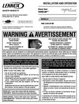
NOTE: DIAGRAMS & ILLUSTRATIONS ARE NOT TO SCALE.
14-7/8”
(378mm)
18-1/2”
(470mm)
32-1/2”
(826mm)
rear vent dimensions
Flue Collar
24-3/4”
(629mm)
28”
(711mm)
dimensions
The gas line attaches to the gas valve at the back of the stove
2-1/2” in from the left side of the stove and 8-1/2” up from
the base of the unit. Test all gas connections for leaks with
a gas leak test solution.
preparing your vision™ stove for installation
Read all instructions before beginning your installation. If
instructions have not been read carefully, your installation
could void your warranty and may create a serious fire,
health, or other safety hazard.
The Lennox Hearth Products warranty will be voided if one
of the following occurs:
• Installation of any damaged stove or vent system
component.
• Unauthorized modification of the direct vent system.
• Installation other than as instructed by Lennox Hearth
Products, Security™ Chimneys, or Simpson Dura-
Vent.
• Installation of any stove or vent system component not
manufactured or approved by Lennox Hearth Products,
Security™ Chimneys, or Simpson Dura-Vent.
When planning the installation for your Vision gas stove, it’s
necessary to consider the following:
• Where the unit is to be installed
• The vent system configuration to be used
• Gas supply (NG or LP)
• Electrical wiring
• Optional accessories (door trim/grill assembly and
wall-mounted or remote thermostat)
top view
front view
Figure 1
Figure 2
Figure 3

8
NOTE: DIAGRAMS & ILLUSTRATIONS ARE NOT TO SCALE.
pipe ClearanCes
All installations using a vertical termination cap must
maintain one inch clearance between the direct vent pipe
and combustibles. For horizontal runs of pipe, one inch of
clearance to combustibles on the sides and bottom, and
two inches on the top of the pipe is required. See page 14
for allowable pipe configurations.
5-5/8”
(143mm)
10”
(254mm)
8-7/8”
(225mm)
Leg on Combustible
Carpet
1-1/2” Maximum
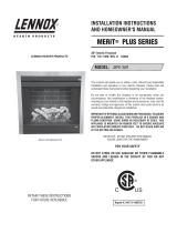
ClearanCes to Combustibles
Minimum clearances to combustible materials in inches
(millimeters):
Parallel Installation
Corner Installation
alCove dimensions
The minimum width between the alcove side walls is 51”
1295mm). The minimum height of the alcove is 46” (1168mm)
and the maximum depth is 35” (889mm).
floor proteCtion
A non-combustible hearth pad is not required. This stove
may be installed on a combustible surface as long as the
combustible material (such as carpeting) does not extend
1-1/2” (38mm) vertically above the bottom of the base.
Also, the floor beneath the stove must be stable, level, hard,
and strong enough to support the stove without a tipping
hazard.
51”
(1295mm)
Min.
35”
(889mm)
Max.
46”
(1168mm)
Min.
Alcove Dimensions
Figure 4
Figure 5
Figure 6
2” (51mm)
15” (381mm)
Min.
24-1/4”
(616mm)
Min.
90°
10”
(254mm)
Figure 7

9
NOTE: DIAGRAMS & ILLUSTRATIONS ARE NOT TO SCALE.
Installation
installing door trim and spring handle
CAUTION: Always ensure that plated surfaces are clean
and free of fingerprints before lighting stove. Fingerprints
will leave permanent blemishes if left on plated surface
when lit. When installation is complete, the trim should
be gently cleaned with a soft cloth and either alcohol or
glass cleaner. Do not overtighten nuts, overtightening can
create visible dimples on the plated surface.
To install the trim on the door, first see Opening and Remov
-
ing Door on page 22. Slide the threaded studs on the trim
through the holes in the door. Install the nuts on the studs
to secure the trim to the door. Do not over tighten the nuts
or they will snap the studs off. To install the spring handle,
first close the door and screw the handle into the receiving
nut. Then spray Windex or water on the shaft of the handle
to act as a lubricant. Next, twist the spring handle counter-
clockwise onto the shaft. Use Windex or alcohol to remove
any fingerprints prior to firing the stove.

10
NOTE: DIAGRAMS & ILLUSTRATIONS ARE NOT TO SCALE.
7. Place the left log on burner supports with the charred
surface facing up. The left log will only fit on the burner
supports in one direction.
8. Place embers around the perimeter of the burner and
sparingly in field of burner. Do not block air holes on the
burner.
briCk panel and log set installation
Caution: If the logs are not properly installed, your stove
will not function correctly.
Parts list: rear log, right log, left log, center log, brick panel
(packaged separately)
1. Remove the logs from the box and carefully unwrap them.
The logs are fragile, so handle them with care.
2. Remove the brick retainer bracket from the upper left
corner inside the stove.
Log Inserts
5. Place rockwool over ports. Rockwool can be placed to
obscure air holes, but do not cover the air holes.
* Fifty percent or less of rockwool supplied should be
used in LP installations. Too much rockwool will result
in tall sooty flames.
6. The right front log (positioned with the black charred
surface toward the front) should be placed on the peg
protruding from the right side of the stove.
Right Log
Embers
Left Log
9. Set center log on support with charred surface toward
you and rest against the rear log.
Brick
Retainer
3. Install the brick panel and replace the brick retainer
bracket.
4. Place the rear log on the back log supports. The charred
surface of the log should face the front.
Figure 8
Figure 9
Figure 10
Figure 11
Figure 12
Figure 13

11
NOTE: DIAGRAMS & ILLUSTRATIONS ARE NOT TO SCALE.
vent installation
Venting:
The Vision™ gas stove has been tested and listed as a direct
vent heater system by OMNI-Test Laboratories, Beaverton,
Oregon and is recommended for use with Security™ Secure
Vent™ pipe*.
Important:
• Read all instructions carefully before starting the instal
-
lation. Failure to follow these instructions may create a
fire or other safety hazard, and will void the warranty.
Be sure to check for specific clearances to combustible
requirements on page 8.
Do not extend the venting sys-
tem vertically or horizontally in excess of the distance
prescribed on page 14. Consult your local building codes
before beginning the installation.
• Always maintain the proper air spaces between the
vent pipe and nearby combustibles to prevent a fire
hazard. Do not fill air spaces with insulation. Be sure to
check the vent termination clearance requirements from
decks, windows, soffits, gas regulators, air supply inlets,
and public walkways, as specified in these installation
instructions on page 15 and local building codes.
• This gas stove and vent system must be vented directly
to the outside of the building, and never be attached to
a chimney serving a separate solid fuel or gas-burning
appliance. Each direct vent gas appliance must use its
own separate vent system. Common vent systems are
prohibited.
• The Vision gas stove is recommended for use with
Security™ Secure Vent pipe*. The appliances, and vent
manufacturers warranties will be voided, and serious fire,
health, or other safety hazards may result from any of the
following actions:
• Installation of any damaged direct vent compo
-
nent.
• Unauthorized modification of the direct vent sys
-
tem.
• Installation of any vent component part not approved
or manufactured by the approved vent manufac
-
turer.
• Installation other than as instructed by Lennox Hearth
Products and vent manufacturers instructions.
residential and mobile home installations:
These are the minimum pieces required. Other parts may
be required for your particular installation.
Minimum Components for Horizontal Installation:
Horizontal Termination Kit which includes:
• 1 6-5/8”x 6” Black Pipe
• 1 Riser Vent Terminal
• 1 Wall Penetration Heat Shield (Wall Thimble) (2 pcs)
• 1 Decorative Wall Trim (black)
• 1 Tube Mill-Pac
• Screws
Optional Components:
• 45º Elbow
• Vinyl Siding Shield for Riser Vent Terminal
• Vent Guard
• Snorkel Termination (36”)
• Snorkel Termination (14”)
• Wall Penetration Heat Shield
Vent Considerations
Twist-lock procedure: Four indentations on female ends of
pipes and fittings are designed to slide straight onto male
ends of adjacent pipes and fittings by orienting the four pipe
indentations so they match and slide into the four entry slots.
Push pipe sections completely together, then twist-lock one
section clockwise approximately one-quarter turn until the
two sections are fully locked. The female locking lugs will not
be visible from the outside on the pipe or fittings. They may
be located by examining the inside of the female ends.
Supports: Horizontal runs of vent must be supported every
3 feet. Wall straps are available for this purpose.
Pipe Sealing: If Simpson Dura-Vent pipe is used, the pipe
must be sealed as follows: seal both the inner and outer
pipes with a high temperature silicone sealant rated for at
least 600º F (commonly know as “RTV”). Run a 1/8” bead
of silicone around outside of male end of outer sleeve. Run
a 1/8” bead of silicone about 1/4” from the end of the male
inner pipe, which is found in the pipe to be attached above.
Twist-lock the pipes or fittings together.
Female Locking
Sealant
Male
Locking
Lugs
Figure 14

12
vent parts list
Direct vent pipe Security™ Secure Vent™ * may be used
with the Vision™ gas stove. Please see the lists below to
verify the components available from each direct vent pipe
manufacturer. Snorkel terminations are available for ap
-
plications which may require vertical rise on the building
exterior. The components listed below come in a galvanized
finish. Most of the components are also available in a painted
black finish. Add a “B” to the end of the part number when
ordering if a black part is desired.
seCurity - seCure vent 6-5/8”x 4” pipe
Part Number Description
SV4LC 6” Pipe Length
SV4L12 12” Pipe Length
SV4L24 24” Pipe Length
SV4L36 36” Pipe Length
SV4L48 48” Pipe Length
SV4LA 6” Pipe, Adjustable
SV4LA12 12” Pipe, Adjustable
SV4FA Flashing, 1/12 to 6/12 Roof Pitch
SV4FB Flashing, 7/12 to 12/12 Roof Pitch
SV4RSM Wall Radiation Shield
SV4E46 45º Elbow
SV4E90 90º Elbow
SV4VS Vinyl Shield Protector
SV4FC Storm Collar
SV4CGV Vertical Termination Cap
SV4BF Firestop
SV4CHC Horizontal Termination Cap
SV4STC36 Snorkel Termination Cap (36”)
SV4STC14 Snorkel Termination Cap (14”)
SV4BM Wall Band
Simpson Dura-Vent GS 6-5/8”x 4” Pipe
Part Number
Description
908 6” Pipe Length
907 9” Pipe Length
906 12” Pipe Length
904 24” Pipe Length
903 36” Pipe Length
902 48” Pipe Length
911 11” to 14-5/8” Pipe, Adjustable
942 Wall Thimble
940 Rnd Support Box/Wall Thimble Cover
941 Cathedral Ceiling Support Box
943 Flashing, 0/12 to 6/12 Roof Pitch
943S Flashing, 7/12 to 12/12 Roof Pitch
945 45º Elbow
990 90º Elbow
950 Vinyl Siding Standoff
953 Storm Collar
963 Ceiling Firestop
988 Wall Strap
981 Snorkel Termination (36”)
982 Snorkel Termination (14”)
984 Horizontal Termination Cap
985 Horizontal Termination Cap (High Wind)
980 Vertical Termination Cap
991 Vertical Termination Cap (High Wind)
horizontal vent installation
venting terminals may not be reCessed into a wall or
siding.
1) Set the unit in the desired location. Check whether or
not wall studs are in the way when the venting system is
attached. If wall studs are in the way, you may want to
adjust the location of the unit.
2) Assemble the desired combination of pipe and elbow to
the appliance adaptor with pipe seams facing down. Off
-
setting the pipe seams as double seams in one place will
cause the outer pipe to take an oval shape. The Horizontal
Termination Kit comes with 18” of straight vent - 6-5/8”
black outer pipe and 4” inner vent.
3) With the pipe attached to the stove, slide the stove into
its correct location, and mark the wall to the dimensions
of the wall thimble (9-1/4” x 10-1/4”). The center of
the round hole should line up with the centerline of the
horizontal pipe. (9-1/4” is side-to-side dimension and
10-1/4” is vertical dimension) If the wall being penetrated
is constructed of non- combustible material (i.e. masonry
block or concrete), a 7” diameter hole is acceptable.
4) The horizontal run of vent should have a 1/4” rise for every
1 foot of run toward the termination. Never allow the vent
to run downward. This could cause high temperatures
and may present the possibility of a fire.
5) The location of the horizontal vent termination on an ex
-
terior wall must meet all local and national building codes,
and must not be blocked or obstructed. For External Vent
Termination Locations, see page 13.
Snorkel Terminations: For installations requiring a vertical
rise on the exterior of the building, 14-inch and 36-inch tall
Snorkel Terminations are available, as well as the standard
Riser Vent. Follow the same installation procedures as
used for standard Horizontal Termination. NEVER install the
snorkel upside down.
Typical parts needed for a horizontal installation.
14” Snorkel for Vision 35
Standard Horizontal for Vision 25
Wall Thimble
Decorative Wall Trim
Pipe Length
max
min
Snorkel required for Vision 35 or
Vision 25 if horizontal run
exceeds 3 feet.
Figure 15

13
NOTE: DIAGRAMS & ILLUSTRATIONS ARE NOT TO SCALE.
flue restriCtors
This stove requires a balanced flue to ensure proper com-
bustion. As such, flue restrictors may need to be installed
depending on the vent configuration of your stove. The
drawings on the following page show all the allowable
pipe configurations for the Vision™ gas stove. To properly
install the flue restrictor, find your pipe configuration in the
drawings on the following page and note which restrictor
setting is recommended. The flue restrictor is shipped in
the firebox of your stove. To install the restrictor, see Figure
18. Remove the two 5/32” allen head screws (A below).
Using pliers, repeatedly bend the unwanted portion of the
flue restrictor and discard. Install the flue restrictor using
the two 5/32” allen head screws according to the diagram
below. Install the flue restrictor screws in their original holes
in the top of the firebox. Restrictor positions are based on
tests run in a laboratory.
Storm Collar
Vertical Termination
Cap
Ceiling Firestop
Framing 10”x 10”
Roof - Maintain 1”
Clearance to
Combustibles
Pipe
Length
Flashing
Hand break to remove
unwanted restrictor
Light Obstructor
(only used for Vision25 w/short
horizontal run & no flue restrictor)
Position 1
Flue Restrictor
Position 3
Position 2
A
vertiCal vent installation
Important Notes
1. All vertically terminated vent installations use 6-5/8”x 4”
Security™ Secure Vent™ pipe*.
2. If the vent passes through a ceiling or floor, a firestop
- Simpson #963 or Security #SV4BF - is required.
3. If the vent passes through the roof, a roof flashing -
Simpson #943 or 943S or Security #SV4FA or SV4FB
- and storm collar - Simpson #953 or Security #SV4FC
- are required.
4. A 1-inch clearance from the vent pipe to combustible
materials must be maintained.
5. A maximum of either two 45º elbows or two 90º elbows
may be used. See page 14 for allowable offsets.
6. The maximum system height is 30 feet and the minimum
is 10 feet.
14” Snorkel
min 12”
Figure 17
Figure 16
Figure 18

14
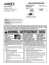
NOTE: DIAGRAMS & ILLUSTRATIONS ARE NOT TO SCALE.
horizontal terminations
The shaded areas in the diagram below show all allow-
able combinations of vent configurations with horizontal
terminations. Horizontal sections of pipe require 1/4” of
rise for every 12” of run. A second 90 degree or 45 degree
elbow (in addition to the first 90 degree elbow at the top of
the vertical length of pipe) is allowed as long as the overall
length of the horizontal run of pipe does not exceed those
shown below. Use the restrictor positions indicated. Note
that if the termination cap falls in the unshaded area below
then no restrictor is installed in the stove.
Combination of vertiCal and horizontal lengths Cannot exCeed 25’.
Straight Horizontal With No Vertical
Vision 25 LP 0-3’ horizontal.......................................Standard Horizontal Cap....................Use Light Obstructor
Vision 25 NG 0-3’ horizontal......................................Standard Horizontal Cap....................Use Light Obstructor
Vision 35 LP 0-3’ horizontal.......................................14” Snorkel Required.........................No Light Obstructor
Vision 35 NG 0-3’ horizontal......................................14” Snorkel Required.........................No Light Obstructor*
Offsets must remain within maximum and minimum lines.
To install the stove with pipe directly out the back, a snorkel
is not required for the Vision™ 25 gas stove. A snorkel is
required for the Vision 35 gas stove. See pages 12 & 13
for snorkel installation instructions.
vertiCal terminations
The diagram below shows all allowable combinations of
straight vertical and offset to vertical vent configurations
with vertical terminations. The termination must fall within
the shaded areas on the diagram. Use the indicated restrictor
positions. Offsets may consist of two 90 degree elbows OR
four 45 degree elbows.
1'
2'
3'
4'
5'
6'
7'
8'
9'
10'
11'
12'
13'
14'
15'
16'
17'
1'
2'
3'
4'
5'
6'
7'
8'
9'
10'
11'
12'
13'
14'
15'
16'
17'
18'
19'
20'
21'
22'
23'
24'
25'
0'
0'
Venting configurations
may not terminate
outside this parameter.
Vision 25 standard cap
#3
#2
#1
#2 #1
#1
Vision 35 requires
14” snorkel
12'
13'
14'
15'
16'
17'
18'
19'
20'
13'
14'
16'
17'
15'
2'
3'
6'
7'
8'
9'
10'
11'
12'
4'
5'
5'
6'
7'
8'
9'
10'
11'
3'
4'
1'
0'
1'
2'
0'
18'
19'
20'
21'
22'
23'
24'
25'
#3
#2
#2
#2
#1
#1 #1
Horizontal Terminations
Vertical Terminations
Figure 19
Figure 20

15
NOTE: DIAGRAMS & ILLUSTRATIONS ARE NOT TO SCALE.
exterior horizontal vent termination ClearanCe requirements
V
V
V
V
V
F
C
B
B
A
B
H
M
I
X
V
D
V
A
A
A
V
L
B
J
X
E
V
A
G
*18”
18”
B
C
C
C
* See Item D in the Text Below.
Center Line
of Termination
Exterior Wall
Horizontal
Termination
Ventilated Soffit
Inside Corner
DETAIL D
Minimum Clearances Canadian Installation * US Installation **
A = Clearance above grade, veranda, porch, deck
or balcony.
12 inches (30 cm) * 12 inches (30 cm) **
B = Clearance to window or door that may be
opened.
6 in. (15.2 cm) for appliances < 10,000 BTU/hr (3kW),
12 in. (30 cm) for appliances > 10,000 BTU/hr (3kW) and <
100,000 BTU/hr (30kW), 36 inches (91 cm) for appliances
> 100,000 BTU/hr (30kW)*
6 in. (15.2 cm) for appliances < 10,000 BTU/hr (3kW),
9 in. (23 cm) for appliances > 10,000 BTU/hr (3kW) and <
50,000 BTU/hr (15kW), 12 inches (30 cm) for appliances
> 50,000 BTU/hr (15kW)*
C = Clearance to permanently closed window 12 inches (305 mm) recommended to prevent window
condensation
9 inches (229 mm) recommended to prevent window
condensation
D = Vertical clearance to ventilated soffit located
above the terminal within a horizontal distance of 18
in. (458 mm) from the center line of the terminal
18 inches (458 mm) 18 inches (458 mm)
E = Clearance to unventilated soffit 12 inches (30 cm) 12 inches (30 cm)
F = Clearance to outside corner 5 inches (12.7 cm) 5 inches (12.7 cm)
G = Clearance to inside corner 6 in. (15 cm) 6 in. (15 cm)
H = Clearance to each inside of center line extended
above meter / regulator assembly
3 feet (91 cm) within a height of 15 feet above the meter /
regulator assembly *
3 feet (91 cm) within a height of 15 feet above the meter
/ regulator assembly **
I = Clearance to service regulator vent outlet 3 feet (91 cm) * 3 feet (91 cm) **
J = Clearance to non-mechanical air supply inlet
to building or the combustion air inlet to any other
appliance
6 in. (15.2 cm) for appliances < 10,000 BTU/hr (3kW), 12
in. (30 cm) for appliances > 10,000 BTU/hr (3kW) and <
100,000 BTU/hr (30kW), 36 inches (91 cm) for appliances
> 100,000 BTU/hr (30kW)*
6 in. (15.2 cm) for appliances < 10,000 BTU/hr (3kW), 9
in. (23 cm) for appliances > 10,000 BTU/hr (3kW) and <
50,000 BTU/hr (15kW), 12 inches (30 cm) for appliances
> 50,000 BTU/hr (15kW)*
K = Clearance to mechanical air supply inlet 6 feet (1.8 meters) * 3 feet (91 cm) above, if within 10 feet (3 m) horizon
-
tally**
L = Clearance above paved sidewalk or paved
driveway located on public property
7 feet (2.13 m) ‡ 7 feet (2.13 m) ‡
M = Clearance under veranda, porch, deck or
balcony
12 in. (30 cm) * ‡ 12 in. (30 cm) ** ‡
* In accordance with the current CSA-B149.1 National Gas and B149.2 Propane Installation Code - Latest Editions.
** In accordance with the current ANSI Z223.1 / NFPA 54 National Fuel Codes - Latest Edition.
‡ A vent shall not terminate directly above a sidewalk or paved driveway which is located between two single family dwellings and serves both dwellings.
*‡ Only permitted if veranda, porch, deck or balcony is fully open on a minimum 2 sides beneath the floor.
Inside
Corner Detail
Operable
Window
Fixed
Closed
Window
= 9" in U.S.
= 12" in C
anada
3 ft.
3 ft.
= Air Supply Inlet
= Vent Terminal
= Area where Terminal is NOT permitted
Figure 21

16
NOTE: DIAGRAMS & ILLUSTRATIONS ARE NOT TO SCALE.
Gas Line Installation
This stove must be connected to the gas line in accordance
with local codes and/or the National Fuel Gas Code, ANSI
Z223.1 (In Canada, the current CAN/CSA B149.1 installation
code). The gas line screws into the gas valve at the back
of the stove 2-1/2” in from the left side of the stove and 8-
1/2”up from the base of the unit. After connecting the gas
line, all joints in the line and connections at the valve should
be checked for leaks.. After connecting the gas line, all joints
in the line and connections at the valve should be checked
for leaks using a gas leak test solution.
gas pressure requirements
A MAJOR CAUSE OF OPERATING PROBLEMS WITH GAS
APPLIANCES IS IMPROPER GAS PRESSURE!
The most important item to check during the initial
installation and the first thing to check when operating
problems occur is gas pressure! This appliance will
not function properly unless the required gas pressure
is supplied. See the table on this page for gas pressure
requirements.
Two pressure taps are provided on the stove’s valve to check
gas pressures. To access the taps, remove the two socket
head screws from the valve control panel. The taps are
located below the on/off/pilot knob. The left tap is the inlet
(supply) pressure side. To check inlet pressure (with the stove
burning) insert a small flat-bladed screwdriver into the tap
and turn a half-turn counter-clockwise. Cover the tap with
the line from the manometer and check the pressure. Close
the tap gently but securely after completing the check. The
manifold (outlet) tap is to the right of the inlet tap. To check
manifold pressure (with the stove burning at the high burn
setting) insert a small flat-bladed screwdriver into the tap
and turn a half-turn counter-clockwise. Cover the tap with
the line from the manometer and check the pressure. Again,
close the tap gently but securely after completing the check.
Check the taps for gas leaks with a gas leak test solution
(retighten if necessary).
If the pressure is not sufficient, make sure the gas supply line
is large enough, the supply regulator improperly adjusted,
and the total gas load for the residence does not exceed the
amount supplied.
The appliance and its individual shut off valve must be
disconnected from the gas supply piping system during
any pressure testing of that system at test pressures in
excess of 1/2 psig.
The appliance must be isolated from the gas supply piping
system by closing its individual manual shut-off valve
during any pressure testing of the gas supply piping system
at test pressures equal to or less than 1/2 psig. Check
with your gas supplier or plumber.
lp and natural gas supplies
Your Vision™ gas stove is equipped from the factory for
use with natural gas only as specified on the Safety / Listing
label attached to the appliance. This appliance can only be
operated using propane gas (LP) if a certified fuel conver
-
sion kit provided by Lennox Hearth Products is installed by
a qualified service technician.
Also check the orifice size on the label on the igniter bracket.
It must be the correct size for the fuel and altitude.
Do not run propane tank dry. Running the tank dry may
cause a hazardous condition due to pressure drop in
empty tank.
Solid fuel is NOT to be used with this unit.
Fuel
Type
Inlet Pressure Manifold Pressure
Desired Minimum Maximum On Hi
Fire
On Lo
Fire
Natural
Gas
7" WC 5" WC 10.5" WC 3.5" WC 1.8" WC
LP Gas 11" WC 11" WC 13" WC 10" WC 6.0” WC

17
Operating Instructions
pre-lighting CheCklist
Be sure to check these items before the initial lighting of
the stove:
c The stove gas label corresponds to the gas supply
available - that is “natural gas” for natural gas or “LP
gas” for LP gas.
c Gas pressure has been checked carefully - see page
16.
c All gas fittings have been checked for leaks.
c All clearances to combustibles have been met - see
page 8.
c All combustible materials have been removed from area
in front of the stove.
c All vented areas of the stove are unobstructed.
c House is ventilated to clear initial paint curing odors
- see page 19.
c All packaging materials have been removed from the
firebox.
c While stove is cool, fingerprints or other marks have
been cleaned from any gold or nickel surfaces with
denatured alcohol and a soft cloth. Marks left on these
surfaces may become etched into the finish if not
removed prior to burning the unit.
c Brick panel, log set, and embers have been installed.
c The glass door is in place and is properly sealed.
Lighting Instructions
The following is a copy of the operating and lighting instruc-
tions found with each stove:
FOR YOUR SAFETY READ BEFORE OPERATING
WARNING: IF YOU DO NOT FOLLOW THESE INSTRUCTIONS
EXACTLY, A FIRE OR EXPLOSION MAY RESULT CAUSING
PROPERTY DAMAGE, INJURY, OR LOSS OF LIFE.
CAUTION: HOT WHILE IN OPERATION. DO NOT TOUCH. KEEP
CHILDREN, FURNITURE, GASOLINE, AND OTHER LIQUIDS
WITH FLAMMABLE VAPORS AWAY. NEVER OPERATE UNIT
WITH GLASS OFF OR ATTEMPT TO REMOVE THE GLASS
WHILE HOT.
A. This appliance is equipped with a piezo ignition device
to light the pilot. When lighting the pilot, follow these
instructions exactly.
B. BEFORE LIGHTING, smell around the appliance area for
gas. Be sure to smell next to the floor, because some gas
is heavier than air and will settle on the floor.
WHAT TO DO IF YOU SMELL GAS:
DO NOT try to light the appliance.
DO NOT touch any electric switch,
DO NOT use any phone in the building. Immediately call
your gas supplier from a neighbor's phone. Follow the gas
supplier's instructions. If you cannot reach your gas supplier,
call the fire department.
C. Use only your hand to push in or turn the gas control
knob. Never use any tool. If the knob will not push in or
turn by hand, don't try to repair it, call a qualified service
technician. Force or attempted repair may result in a fire
or explosion.
D.
DO NOT use this appliance if any part has been under water.
Immediately call a qualified service technician to inspect
the appliance and to replace any part of the control system
and any gas control which has been under water.
OPERATING INSTRUCTIONS
CAUTION: Your Lennox™ gas APPLIANCE MUST ALWAYS
BE OPERATED WITH GLASS IN PLACE.
STOP!! Read the safety information above before pro-
ceeding.
1. Open the lower door. Make sure gas supply shut-off cocks
are open and ON/OFF rocker switch is "OFF." If equipped
with a thermostat, set it to the lowest setting.
2. Turn off all electrical power to the appliance.
3. Push in gas cock dial slightly and turn clockwise to
"OFF."
NOTE: Dial cannot be turned from "PILOT" to "OFF" unless
dial is pushed in slightly. Do not force.
4. Wait five minutes to clear out any gas. Then smell for gas,
including near the floor. If you smell gas, STOP! Follow
"B" above. If you don't smell gas continue.
5. Locate the pilot by looking over the top of the left front
log. A blue flame will be seen when the pilot is lit.
6. Turn the gas control knob counter-clockwise to
the "PILOT" position.
7. Push the knob all the way in and hold in that position.
Immediately light the pilot by pressing the igniter button
several times until pilot is lit. Continue to hold the knob
in for about 30 seconds after the pilot is lit. Realease
knob and it will pop back out. Pilot should remain lit. If it
goes out, repeat steps 4-8 holding knob in an additional
15 seconds after pilot is lit. If knob does not pop out
when released, stop and immediately call your service
technician or gas supplier. If the pilot will not stay lit after
several tries, turn the gas control knob to "OFF" and call
your service technician or your gas supplier.
8. After pilot is lit, turn gas control knob counter-clockwise
to "ON." Knob can only be turned to "ON" if the
knob has popped out.
9. To turn burner on, turn "ON/OFF" rocker switch to "ON"
or set the thermostat to the desired temperature above
room temperature.
10. Adjust the flame height (and heat output) by turning the
flame height knob clockwise for full flame and
counter-clockwise for reduced flame.
11. Turn on the electric power to the appliance and set the
blower to the desired air flow after it turns on when the
appliance reaches operating temperature.

18
NOTE: DIAGRAMS & ILLUSTRATIONS ARE NOT TO SCALE.
TO TURN OFF GAS TO APPLIANCE
1. Turn off the "ON/OFF" rocker switch and/or thermostat (if
installed) to its lowest setting.
2. Turn off electric power to the appliance if service is to
be performed.
3. Push in gas control knob slightly and turn clockwise
to "OFF." Do not force.
This appliance needs fresh air for safe operation and
must be installed so there are provisions for adequate
combustion and ventilation air.
WARNING: Improper installation, adjustment, alteration,
service, or maintenance can cause injury or property dam-
age. For assistance or additional information, consult a
qualified installer, service agency, or your gas supplier.
Operation of this appliance when not connected to a prop-
erly installed and maintained venting system can result in
carbon monoxide (CO) poisoning and possible death.
SHUTDOWN PROCEDURE
To turn off the burner, turn the rocker switch to "OFF" or
adjust the thermostat (if installed) to a setting below room
temperature. The pilot will remain lit for future burner igni
-
tion. For complete shutdown, see "TO TURN OFF GAS TO
APPLIANCE" above.
Flame Color & Behavior
Your Vision™ gas stove is designed for maximum heating
efficiency. Therefore, upon lighting of the main burner the
flames will be semi-transparent or “bluish.” After 10-20
minutes of operation the logs will heat up and the flames
will become a yellow/orange color.
Adjusting the stove to cause the flames to turn orange sooner
may result in poor combustion, sooting, and a hazardous
situation. See the drawing to the right showing proper flame
appearance.
SIT Millivolt Gas Valve
Gas Control Knob
(Pilot / On / Off)
Flame Height Control
Knob (HI/LO)
No Blue Flame
Center
Soot at
Flame Tip
Dark Orange
Flame
IMPROPERLY
BURNING FLAME
Soot above
Flame Tip
No Soot at
Flame Tip
PROPERLY
BURNING FLAME
Semi-Transparent
Yellow Flame
Blue Flame
Center
Ports on Pan
Burner Assembly
Burner Flame Appearance
Figure 22
Figure 24
Pilot Flame Appearance
Figure 25
Igniter
ON
PILOT
OFF
HI
LO
Gas Control Knob
(pilot/on/off)
Blower
On/Off
Switch
Flame Height
Control Knob
- LO / HI +
Figure 23

19
NOTE: DIAGRAMS & ILLUSTRATIONS ARE NOT TO SCALE.
air shutter adjustment
CAUTION: Air shutter is hot while the Vision™ gas stove
is operating and should only be adjusted using a heat
resistant glove.
The air shutter control lever is located on the bottom of the
stove directly to the left of the gas valve. The lever is linked
to the primary air shutter on the main burner. The air shutter
regulates the amount of primary air the burner receives and,
therefore, how clean the stove burns. The air shutter should
only be adjusted by a qualified gas technician. The stove
should burn for about 15 minutes with the logs installed
before adjusting the air shutter. Moving the lever to the left
will open the shutter and turn the flames more transparent
and blue. Moving the lever to the right will close the shutter
and turn the flames more orange.
Caution: The air shutter
should never be set so as to make the tips of the flames
sooty or create sooting on the viewing glass, logs, or firebox
ceiling. If soot begins to form after burning, the air shutter
should be opened gradually until the sooting condition
stops. Gas quality and gas pressure may vary, which can
affect the burning characteristics of the stove.
quiet operation
As the Vision gas stove is burning, a number of normal op-
erational sounds may be heard. The flow of gas through the
gas valve and orifice may make a rushing or whistling noise.
If this noise is objectionable, it can be reduced by turning
down the flame. Turning down the flame can reduce total
heat output by more than 30%. When the blower turns on,
the sound of rushing air may be heard. The blower sounds
may be reduced by adjusting the speed control located on the
blower assembly. Also, a slight clicking sound may be heard
as the gas valve or blower switch is turned on and off.
paint Curing
This stove has been painted with StoveBright high tempera-
ture metallic paint. It leaves the factory dry to the touch, but
completes the curing process as the stove is used. To cure
the paint, burn the appliance four successive times for ten
minutes each time with a five minute cool down between
each firing. Also some parts of the appliance may be lightly
coated with machining oil. Ventilate the house during these
first firings as the paint and oil give off carbon dioxide and
unpleasant odors. It is recommended that persons sensi
-
tive to an imbalance in the indoor air quality avoid the stove
during the curing process.
Figure 26
Shutter Adjustment Handle
Locate in lower compartment to the right of the valve.
Turn the handle to the left to open and to the right to close.

20
NOTE: DIAGRAMS & ILLUSTRATIONS ARE NOT TO SCALE.
operating options
Your stove comes equipped with an “On/Off” rocker switch
used to turn the burner on and off while the pilot light is
on. The switch is a round rocker switch located behind the
main control panel door.
A millivolt wall thermostat, or a remote control, can be used
to supplement the rocker switch. The gas valve is powered
by millivolts generated by the pilot assembly. This millivolt
system is very sensitive to electrical resistance, therefore,
make sure all connections are tight, clean, and free from
corrosion. Do not splice any millivolt wires. Consult the
table below to determine the proper gage of wire for the
thermostat or wall switch connections. This table refers
to the total length of the wire (out to the switch and back).
The thermostat must be a millivolt type. A 24-volt furnace
thermostat will not work. Never hook up household current
- 120 Volts - to the millivolt system. It is not recommended
to hook up any more than two switches to the stove (for
example a rocker switch and a wall thermostat). Additional
switches may affect the system resistance and increase the
chance of the burner not igniting.
Follow the instructions included with the thermostat or
remote control for wiring. The thermostat, remote control,
and rocker switch will turn the burner on and off indepen
-
dently. Be sure to set the rocker switch to the “Off” position
when using the thermostat or remote control, and set the
thermostat or remote control to the lowest temperature when
you wish to use the rocker switch only, otherwise one may
override the other.
millivolt Control system
This stove operates on a millivolt control system. As such,
no additional power supply is needed for the stove to heat.
The pilot assembly contains a thermocouple that, when
heated by the pilot flame, generates electricity (millivolts-
mV=1/1000 of a volt) which opens a valve allowing gas to
continue flowing to the pilot assembly. The pilot assembly
also contains a thermopile that, when heated by the pilot
flame, generates electricity that flows to terminal #1 (labeled
TPTH) on the gas valve. When the electricity is conducted
from terminal #1 through the on/off switch, thermostat, or
receiver of the remote control to terminal #3 (labeled TH)
on the gas valve, the main burner will ignite.
Figure 27
Millivolt Control Schematic
Thermopile
ON/OFF Rocker Switch,
Thermostat, or Remote
Thermostat
Piezo Igniter
Thermocouple
Pilot Gas Line
Sparker
Pilot Hood
Pilot Assembly
Gas Inlet
Pressure Taps
Terminal 3Terminal 1
Terminal 2
Gas Valve
Wiring Terminals
CAUTION: Label all wires prior to disconnection when
servicing controls. Wiring errors can cause improper
and dangerous operation. Verify proper operation after
servicing.
Thermostat Wire
Wire Size Maximum Length
12 Gage
100 Feet
14 Gage 64 Feet
16 Gage
40 Feet
18 Gage 25 Feet
20 Gage 16 Feet
/