Real Fyre D1 Operating instructions
- Category
- Fireplaces
- Type
- Operating instructions
This manual is also suitable for

1
Robert H. Peterson Co. • 14724 East Proctor Avenue • City of Industry, CA 91746
IMPORTANT: READ THESE INSTRUCTIONS
CAREFULLY BEFORE STARTING
INSTALLATION OR USE.
INSTALLATION &
OWNER’S MANUAL
Do not store or use gasoline or other
flammable vapors and liquids in the
vicinity of this or any other appliance.
WHAT TO DO IF YOU SMELL GAS:
• Open a window.
• Do not try to light any appliance.
• Do not touch any electrical switch; do
not use any phone in the building.
• Leave the building immediately.
• Immediately call the gas supplier
from a neighbor’s phone. Follow gas
supplier’s instructions.
• If you cannot reach the gas supplier,
call the fi re department.
Installation and service must be performed
by a qualified professional installer,
service agency, or the gas supplier.
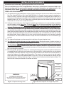
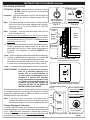
DESIGN CERTIFIED
to
Vented Gas Fireplace Heater
ANSI Z21.88-2014
CSA 2.33-2014
INSTALLER:
Leave this manual with the appliance.
CONSUMER:
Retain this manual for future reference.
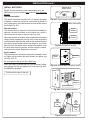
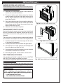
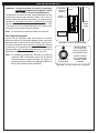
This appliance may be installed in an
aftermarket, permanently located,
manufactured home (USA only) or mobile
home, where not prohibited by local codes.
This appliance is only for use with the type
of gas indicated on the rating plate. This
appliance is not convertible for use with other
gases, unless a certifi ed kit is used.
12-051
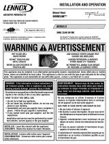
WARNING:
FIRE OR EXPLOSION HAZARD
Failure to follow safety warnings exactly could
result in serious injury, death, or property damage.
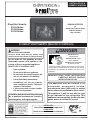
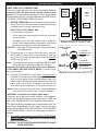
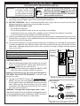
DANGER
A barrier designed to reduce the risk of burns from the hot
viewing glass is provided with this appliance and shall be
installed for the protection of children and other at-risk
individuals.
HOT GLASS WILL
CAUSE BURNS.
DO NOT TOUCH GLASS
UNTIL COOLED.
NEVER ALLOW CHILDERN
TO TOUCH GLASS.
REV 1 - 1601150815
L-A2-406
D1 DIRECT VENT INSERTS (MILLIVOLT CONTROLS)
Direct Vent Inserts:
D1-25 Series
D1-30 Series
D1-36 Series
Page is loading ...

3
TABLE OF CONTENTS
IMPORTANT SAFETY INFORMATION
Congratulations on your purchase of an R. H. Peterson Co. Real Fyre direct vent insert. Made with pride in
America, your new insert complies with national safety standards and when installed per these instructions and
used as intended it will provide warmth and comfort to your home for many years.
Due to the extreme heat output of the insert, there is a risk of burns if care is not taken in the operation of
the unit. PLEASE READ THE SAFETY AND OPERATION INFORMATION AND WARNINGS IN THIS MANUAL
BEFORE USING YOUR INSERT. Be aware that glass panels and other surfaces get extremely HOT and can
cause burns if touched. Factory-provided barrier screens help to reduce the risk of serious burns as they can
prevent direct contact with the glass. However, barrier screens still retain heat and must not be touched. The
insert glass and surrounding material will remain HOT for a period of time after the unit is turned off, so caution
should be used at all times.
Refer to all safety information and warnings provided in this manual.
REV 1 - 1601150815
L-A2-406
GETTING STARTED
IMPORTANT PRE-INSTALLATION AND SAFETY
INFORMATION ..............................................................5
NOTES PAGE .................................................................6
LISTING AND CODE APPROVALS .............................7
LISTING ...................................................................7
CODE REQUIREMENTS ...........................................7
COMMONWEALTH OF MASSACHUSETTS
REQUIREMENTS
...................................................... 7
SPECIFICATIONS AND DIMENSIONS .......................8
MINIMUM CLEARANCES TO COMBUSTIBLES ...13
TOOLS REQUIRED .....................................................13
REPLACEMENT PARTS LIST ....................................14
INSTALLATION REQUIREMENTS ...........................21
FIREPLACE REQUIREMENTS ................................21
GAS PRESSURE REQUIREMENTS ..........................22
VENTING REQUIREMENTS ....................................22
INSTALLATION
INSTALLATION ...........................................................24
BEFORE YOU BEGIN .............................................24
GAS SUPPLY SETUP ..............................................24
ELECTRICAL SETUP ..............................................24
VENTING ...............................................................25
DIRECT VENT INSERT ...........................................27
INSTALL BATTERIES ..............................................28
FIRST TIME PILOT LIGHTING TEST ......................29
FIRST TIME BURNER LIGHTING TEST ...................30
GAS PRESSURE TEST .............................................30
REFRACTORY PANELS ...........................................31
GLOWING EMBERS ...............................................33
LOG SET PLACEMENT ...........................................34
GLASS PANEL.........................................................37
POWER SUPPLY.....................................................37
INITIAL AIR SHUTTER ADJUSTMENT ....................37
BARRIER SCREEN AND SURROUND ......................38
SECURE DIRECT VENT TO FLOOR ........................38
FIRST TIME BURN-OFF PERIOD ...........................38
USE, CARE, & SERVICE
LIGHTING INSTRUCTIONS ......................................39
FOR YOUR SAFETY READ BEFORE LIGHTING ...... 39
LIGHTING THE PILOT ...........................................39
REMOTE LIGHTING ............................................... 41
MANUAL LIGHTING...............................................43
SHUTTING DOWN .................................................. 43
FAN OPERATING INSTRUCTIONS...........................45
SERVICING AND CLEANING ...................................47
ANNUAL CLEAN / INSPECTION .............................47
GLASS PANEL REMOVAL AND MAINTENANCE ......48
PILOT BURNER CHECK/ADJUSTMENT .................48
AIR SHUTTER ADJUSTMENT .................................49
BATTERY REPLACEMENT ......................................51
FAN ASSEMBLY CLEANING .................................... 53
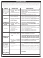
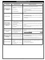
TROUBLESHOOTING ................................................54
WARRANTY .................................................................56
Page is loading ...

5
IMPORTANT PRE-INSTALLATION AND SAFETY INFORMATION
WARNING!
A. Read all instructions. Do not install or operate this appliance without fi rst reading and understanding this
manual. Failure to follow the instructions in this manual will result in an improperly installed and operating
appliance, void the warranty, and can be dangerous.
B. Improper installation, adjustment, alteration, service, maintenance, or use can cause serious injury, death or
property damage. Refer to this manual. For assistance or additional information consult a qualifi ed professional
service technician, service agency or the gas supplier.
C. Provisions for adequate combustion and ventilation air must be maintained. See the VENTING REQUIREMENTS
section for details.
D. Electrical Grounding Instructions - This appliance is equipped with a three-prong (grounding) plug for your
protection against shock hazard and should be plugged directly into a properly grounded three-prong
receptacle. Do not cut or remove the grounding prong from this plug.
E. Failure to position the parts in accordance with this manual or failure to use only parts specifi cally approved
with this appliance may result in property damage or personal injury.
F. Installation, service, and repair must be done by a qualifi ed professional service technician.
G. A local building inspector should review your plans prior to installation.
H. Use extreme caution whenever handling this product and its accessories as they have sharp edges that can
cause personal injury.
I. It is recommended that smoke detectors are installed in the home. If possible, install a detector in a hallway
adjacent to the room (to prevent a false alarm from the heat of the appliance). However, you must follow the
requirements of the local code.
J. Any modifi cation or alteration may void the warranty, certifi cation and listings of this appliance.
K. Adequate accessibility clearances for servicing and proper operation must be provided.
L. Adequate clearance around air openings into the combustion chamber must be maintained.
M. This gas appliance must not be connected to a chimney fl ue serving a separate solid-fuel burning appliance.
N. Do not use this appliance if any part has been under water. Immediately call a qualifi ed service technician
to inspect the appliance and to replace any part of the control system and any gas control which has been
under water.
O. Due to high temperatures, the appliance should be located out of traffi c and away from furniture and draperies.
P. Hot while in operation. Children and adults should be alerted to the hazards of high surface temperature and
should stay away to avoid burns or clothing ignition.
Q. Young children should be carefully supervised when they are in the same room as the appliance. Toddlers,
young children and others may be susceptible to accidental contact burns. A physical barrier is recommended
if there are at-risk individuals in the house. To restrict access to a fi replace or stove, install an adjustable safety
gate to keep toddlers, young children and other at risk individuals out of the room and away from hot surfaces.
R. Clothing or other fl ammable material should not be placed on or near the appliance. Never place solid fuels,
fl ammable liquids, or foreign objects into this appliance.
S. Any safety screen or guard removed for servicing an appliance must be replaced prior to operating the appliance.
T. Installation and repair should be done by a qualifi ed service person. The appliance should be inspected before
use and at least annually by a professional service person. More frequent cleaning may be required due to
excessive lint from carpeting, bedding material, et cetera. It is imperative that control compartments, burners
and circulating air passageways of the appliance be kept clean.
U. Only trim kit(s) supplied by the manufacturer shall be used in the installation of this appliance. Draft relief
openings must not be covered or blocked. Trim panels or surrounds must not seal ventilation openings in
the fi replace.
SAVE THESE INSTRUCTIONS

6
NOTES PAGE
Please use this page to record any information that you may want to have at hand.

7
LISTING AND CODE APPROVALS
LISTING
This direct vent insert has been certifi ed to:
VENTED GAS FIREPLACE HEATER ANSI Z21.88, CSA 2.33
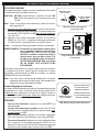
It has been certifi ed for use with either natural or propane gas, and is approved for installation in bedrooms and
aftermarket manufactured (mobile) homes.
CODE REQUIREMENTS
A. The installation must conform with local codes or, in the absence of local codes, with the National Fuel Gas
Code, ANSI Z223.1/NFPA 54, or the Natural Gas and Propane Installation Code, CSA B149.1.
B. Ensure clearances are in accordance with local installation codes and the requirements of the gas supplier.
Dégagement conforme aux codes d’installation locaux et aux exigences du foumisseunde gaz.
C. A manufactured home (USA only) or mobile home OEM installation must conform with the Manufactured
Home Construction and Safety Standard, Title 24 CFR, Part 3280, or, when such a standard is not applicable,
the Standard for Manufactured Home Installations, ANSI/NCSBCS A225.1, or Standard for Gas Equipped
Recreational Vehicles and Mobile Housing, CSA Z240.4.
D. The appliance, when installed, must be electrically grounded in accordance with local codes or, in the
absence of local codes, with the National Electrical Code, ANSI/NFPA 70, or the Canadian Electrical Code,
CSA C22.1.
E. To comply with certifi cation, and building code acceptances, and for safe operation and proper performance
of this appliance, use ONLY Peterson parts and accessories. Use of other controls, parts, and accessories
that are not designed for use with Real Fyre direct vent inserts is prohibited and will void all warranties,
certifi cations, and building code approvals, and may cause property damage, personal injury, or loss of life.
COMMONWEALTH OF MASSACHUSETTS REQUIREMENTS
This appliance is approved for installation in the state of Massachusetts subject to the following requirements:
A. Install this appliance in accordance with 248 C.M.R., the Rules and Regulations Governing Plumbers and
Gas Fitters.
B. The installer or service agent must be a plumber or gas fi tter licensed in the Commonwealth of Massachusetts.
C. The fl exible gas line connector used must not exceed 36 inches (92 centimeters) in length.
D. The individual manual shut-off must be a T-handle type valve, listed and approved by the state of Massachusetts.

8
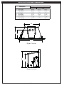
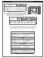
Table 1 - Product Dimensions
EXHAUST INTAKE
SPECIFICATIONS AND DIMENSIONS
Fig. 8-1 Top View
Fig. 8-2 Side View
A
B
C
D
E
F
Description
Dimension
D1-25 D1-30 D1-36
A. Rear Width 20
1
/
8
" 20
1
/
2
" 23"
B. Front Width 29" 31
1
/
2
" 34
1
/
2
"
C. Unit Depth 13
1
/
4
" 16
1
/
4
" 17
1
/
4
"
D. Vent Depth 6
1
/
2
"9
1
/
2
"9
1
/
2
"
E. Rear Height 15
1
/
2
" 18
1
/
8
" 21
3
/
8
"
F. Front Height 18
1
/
2
" 21
1
/
2
" 25"
Description
Dimension
D1-25 D1-30 D1-36
A. Rear Width 20
3
/
8
" 21
1
/
4
" 23
1
/
2
"
B. Front Width 30
3
/
8
" 34
3
/
4
" 37
5
/
8
"
C. Unit Depth 14
1
/
8
" 16
1
/
4
" 17
1
/
4
"
D. Vent Depth 8
7
/
8
" 11
3
/
8
" 11
3
/
8
"
E. Rear Height 15
5
/
8
" 19" 21
3
/
4
"
F. Front Height 18
7
/
8
" 21
7
/
8
" 25
1
/
2
"
EXHAUST INTAKE
Fig. 8-1 Top View
Fig. 8-2 Side View
A
B
C
D
E
F

9
SPECIFICATIONS AND DIMENSIONS (cont.)
Fig. 9-1 Front View (3 sided surround model) Fig. 9-2 Front View (4 sided surround model)
B
A
Fig. 9-3
Side View
C
DD
E
B
A
C
DD
C
Description
ABCDE
D1-25
Surround 3-sided, small 34
3
/
8
" 22" 4
1
/
2
"4
3
/
4
"1
1
/
2
"
Surround 3-sided, medium 37
3
/
8
" 25
1
/
4
"7
3
/
4
"6
1
/
4
"1
1
/
2
"
Surround 3-sided, large 40
3
/
8
" 28" 10
1
/
2
"7
3
/
4
"1
1
/
2
"
Surround 4-sided, small 34
3
/
8
" 27" 4
3
/
4
"4
3
/
4
"1
1
/
2
"
Surround 4-sided, medium 37
3
/
8
" 30" 6
1
/
4
"6
1
/
4
"1
1
/
2
"
D1-30
Surround 3-sided, small 38
3
/
8
" 25" 4
3
/
4
"4
1
/
2
"1
1
/
2
"
Surround 3-sided, medium 41
3
/
8
" 28" 6
1
/
4
"7
1
/
2
"1
1
/
2
"
Surround 3-sided, large 44
3
/
8
" 31" 7
3
/
4
" 10
1
/
2
"1
1
/
2
"
Surround 4-sided, small 38
3
/
8
" 30" 4
3
/
4
"4
3
/
4
"1
1
/
2
"
Surround 4-sided, medium 41
3
/
8
" 33" 6
1
/
4
"6
1
/
4
"1
1
/
2
"
D1-36
Surround 3-sided, small 43
3
/
8
" 29" 5" 5
3
/
4
"1
1
/
2
"
Surround 3-sided, medium 45
3
/
8
" 32" 8" 6
3
/
4
"1
1
/
2
"
Surround 3-sided, large 49
3
/
8
" 35" 11" 8
3
/
4
"1
1
/
2
"
Surround 4-sided, small 43
3
/
8
" 33" 4
1
/
2
"5
3
/
4
"1
1
/
2
"
Surround 4-sided, medium 45
3
/
8
" 36" 6" 6
3
/
4
"1
1
/
2
"
Table 2 - Surround Kit Dimensions
Fig. 9-1 Front View (3 sided surround model) Fig. 9-2 Front View (4 sided surround model)
B
A
Fig. 9-3
Side View
C
DD
E
B
A
C
D
D
C

10
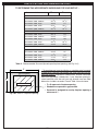
TO DETERMINE THE APPROPRIATE SURROUND FOR YOUR SETUP* :
SPECIFICATIONS AND DIMENSIONS (cont.)
Recommended surround
F max G max
D1-25
Surround 3-sided, small 32
3
/
8
" 21"
Surround 3-sided, medium 35
3
/
8
" 24
1
/
4
"
Surround 3-sided, large 38
3
/
8
" 27"
Surround 4-sided, small 32
3
/
8
" 19
3
/
4
"
Surround 4-sided, medium 35
3
/
8
" 24
1
/
4
"
D1-30
Surround 3-sided, small 36
3
/
8
" 24"
Surround 3-sided, medium 39
3
/
8
" 27"
Surround 3-sided, large 42
3
/
8
" 30"
Surround 4-sided, small 36
3
/
8
" 24
1
/
4
"
Surround 4-sided, medium 39
3
/
8
" 25
3
/
4
"
D1-36
Surround 3-sided, small 41
3
/
8
" 28"
Surround 3-sided, medium 43
3
/
8
" 31"
Surround 3-sided, large 47
3
/
8
" 34"
Surround 4-sided, small 41
3
/
8
" 27
1
/
2
"
Surround 4-sided, medium 43
3
/
8
" 29"
Fig. 10-1 Insert in Fireplace Opening
G
F
Table 3 - Recommended Surround (based upon fi replace opening, see Fig. 10-1)
(Direct vent insert)
• F x G represents fi replace opening
• Shaded area represents gap created
• Surround is designed to overlay fi replace opening a
minimum of 1"
* To complete your insert installation, a matching metal surround
is required to cover the gap between the insert and your existing
fi replace opening. Available in a black fi nish, choose from three
fi xed, non-adjustable 3-sided sizes. If your fi replace opening is
raised and fl ush with the wall; you may choose from two fi xed
dimension 4-sided surrounds. Consult Table 3 for assistance.
(gap in fi replace)

11
SPECIFICATIONS AND DIMENSIONS (cont.)
Fig. 11-1 Minimum Fireplace Dimensions
A
B
C
D
* For elevations above 2,000 feet, the BTU rate of the unit is reduced by
4% for each additional 1,000 feet. To install the unit above an elevation of
2,000 feet, you must use proper orifi ces based on the de-rated BTU.
Remote Control
Supply voltage
4.5 V
(three 1.5 V AAA batteries)
Ambient temperature ratings 32 - 122 °F (0-50 °C)
Radio frequency 315 MHz
Receiver
Supply voltage
6.0 V
(four 1.5 V AA batteries)
Ambient temperature ratings 32 - 140 °F (0-60 °C)
Radio frequency 315 MHz
Fan Control Module
Supply voltage/frequency 120 V / 60 Hz
Ambient temperature ratings 32 - 140 °F (0-60 °C)
Output voltage/frequency/current 120 V / 60 Hz / 5 A
Aux switched output 120 V / 60 Hz / 2 A
Fan speed output 120 V / 60 Hz / 1 A
Table 6 - Technical Data Specifi cations
Note: If exhaust collar on direct vent insert and fi replace
damper do not line up, add 3 inches to minimum
fi replace height to allow offsets of vent pipe.
Description
Dimension
D1-25 D1-30 D1-36
A. Front Width 30" 34"
37"
B. Rear Width 20
1
/
2
" 21" 23
3
/
8
"
C. Depth 15" 18
1
/
2
" 19
1
/
2
"
D. Height 19" 22" 25
1
/
2
"
Model
Natural Gas Propane Gas
BTU
Rating
Orifi ce Size
BTU
Rating
Orifi ce Size
Front Rear Front Rear
D1-25
(0-2000 FT)
* 25,000 #42 - 20,000 #55 -
D1-30
(0-2000 FT)
* 32,000 #50 #45 31,000 #57 #55
D1-36
(0-2000 FT)
* 38,000 #48 #43 36,000 #57 #54
Table 5 - BTU Ratings and Orifi ce Sizes
Table 4 - Minimum Fireplace Dimensions
Description
Dimension
D1-25 D1-30 D1-36
A. Front Width 30
1
/
2
" 35" 38"
B. Rear Width 21" 21
1
/
2
" 23"
C. Depth 15
1
/
4
" 18
1
/
4
" 19
1
/
4
"
D. Height 19" 22" 25
1
/
2
"
Remote Control
Supply voltage
4.5 V
(one 12V battery)
Ambient temperature ratings 32 - 122 °F (0-50 °C)
Radio frequency 304 MHz
Receiver
Supply voltage
6.0 V
(four 1.5 V AA batteries)
Ambient temperature ratings 32 - 130 °F (0-60 °C)
Radio frequency 304 MHz
Fan Control Module
Supply voltage/frequency 120 V / 60 Hz
Ambient temperature ratings 32 - 140 °F (0-60 °C)
Output voltage/frequency/current 120 V / 60 Hz / 5 A
Electronic Igniter
Supply voltage
1.5 V
(one 1.5 V AA battery)
Ambient temperature ratings 140 °F (60 °C)
Model
Natural Gas Propane Gas
BTU
Rating
Orifi ce Size
BTU
Rating
Orifi ce Size
Front Rear Front Rear
D1-25
(0-2000 FT)
* 25,000 #42 - 20,000 #55 -
D1-30
(0-2000 FT)
* 32,000 #50 #45 31,000 #59 #55
D1-36
(0-2000 FT)
* 40,000 #48 2.2 mm 40,000 #57 1.5 mm
Table 4 - Minimum Fireplace Dimensions

12
SPECIFICATIONS AND DIMENSIONS (cont.)
Fig. 12-2
VALVE
(NAT/LP)
PROFLAME
FCM CONTROL
MODULE
GAS TUBE TO
REAR BURNER
GAS TUBE TO
FRONT BURNER
VALVE
SPLIT
FLOW
GROUND WIRE
PROFLAME
RECEIVER
PROFLAME
WIRE HARNESS
PROFLAME
WIRE HARNESS
WIRE EXT. ON/OFF SWITCH
PROFLAME
DFC BOARD
SPARK ELECTRODE
SENSE ELECTRODE
PILOT (NAT/LP)
D1-25 WIRING DIAGRAM
D1-30 & D1-36 WIRING DIAGRAM
Fig. 12-1
VALVE
(NAT/LP)
PROFLAME
FCM CONTROL
MODULE
SWITCH PILOT
FLAME MODULE
GAS TUBE
TO BURNER
PILOT TUBE
GROUND WIRE
PROFLAME
RECEIVER
PROFLAME
WIRE HARNESS
PROFLAME
WIRE HARNESS
WIRE EXT. ON/OFF SWITCH
PROFLAME
DFC BOARD
SPARK ELECTRODE
SENSE ELECTRODE
PILOT (NAT/LP)
PILOT TUBE
PILOT
THERMOSTAT
SWITCH PILOT
FLAME MODULE
PILOT
THERMOSTAT
Fig. 12-2
D1-25 WIRING DIAGRAM
D1-30 & D1-36 WIRING DIAGRAM
Fig. 12-1
PILOT ASSY
FAN ASSY
THERMAL
DISC SENSOR
WIRE HARNESS
REMOTE RECEIVER
IGNITER MODULE
FAN ADJ.
KNOB
BURNER
ON/OFF
SWITCH
GAS TUBE
TO BURNER
VALVE ASSY
PILOT ASSY
FAN ASSY
THERMAL
DISC SENSOR
WIRE HARNESS
REMOTE RECEIVER
IGNITER MODULE
FAN ADJ.
KNOB
BURNER
ON/OFF
SWITCH
GAS TUBE TO
FRONT BURNER
VALVE ASSY
GAS TUBE TO
REAR BURNER

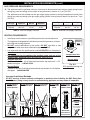
13
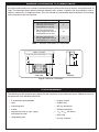
MINIMUM CLEARANCES TO COMBUSTIBLES
All minimum clearances from surfaces to combustible construction/materials must be met, and maintained at all
times. The clearances shown below include any adjacent walls, spacers, standoffs, and any projections such as
shelves, window sills, or fi replace mantels. They also include any combustible decorations/items. Any fi nishing
on the mantel must be heat resistant.
TOOLS REQUIRED
The following are the minimum tools required for the installation of your direct vent insert. Additional tools may
be required for your individual installation.
• 2 assemblers recommended
• rope
• measuring tape
• marker
• appropriate tools for gas supply
and electrical install
• reciprocating saw
• hi temp. sealant
• cordless drill
• drill bits and drivers
• Phillips screwdriver
•
5
/
16
" &
7
/
16
" nut drivers
• utility knife
• tin snip / hacksaw
Description Dimension
A.
Clearance required from the
side edge of the insert to
combustibles or side wall
6"
B.
Clearance required from
the top edge of the insert to
combustibles or 8" mantel
16"
C.
Clearance required from
the top edge of the insert to
combustibles or 12" mantel
22"
Fig. 13-1 Minimum Clearances
Table 7 - Minimum Clearances to Combustibles
A
B
C
Mantel - 12" Depth
Combustible Trim or Mantel Depth of 8" or less
FRONT VIEW SIDE VIEW
8"
12"
B
C

14
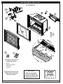
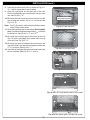
REPLACEMENT PARTS LIST
Robert H. Peterson Co. • 14724 East Proctor Avenue, • City of Industry, CA 91746
IMPORTANT
Remove all packing
material (including any
protective coatings) and
discard prior to use.
Your direct vent insert is
shipped in 4 boxes:
• Insert
• Refractory panels
• Surround
• Log set
Replacement parts can be
ordered from your local
Real Fyre dealer.
SHARP
EDGES
USE CAUTION
D1-25 MODELS
OFF
ON
17
7
15
9
8
20
5
16
22
23
6
18
4
2
13
11
10
12
1

15
REPLACEMENT PARTS LIST (cont.)
D1-25 MODELS
Item Description Part No. Qty.
1. Control valve (Nat) D1-30-721 1
or Control valve (LP) D1-30-722 1
2. Burner assembly D1-25-703 1
3. Burner orifi ce (Nat)* 3001-42-1 1
or Burner orifi ce (LP)* 3001-55-1 1
4. Pilot assembly (Nat) D1-25-725 1
or Pilot assembly (LP) D1-25-726 1
5. Fan assembly D1-30-736 1
6. Thermal disc sensor TS-3 1
7. Grate D1-25-707 1
8. Glass panel assembly D1-25-900 1
9. Fine mesh barrier screen D1-25-913M 1
10. Fan HI/LO adjustment knob KNOB-11 1
11. Igniter module OCR-34-21 1
12. Burner On/Off switch SW-9 1
13. Lintel D1-25-902 1
14. Spring door latch * D1-30-910 1
15. Remote transmitter AT-R1-1 1
16. Remote receiver RR-1A 1
17. Air fl ow screen D1-25-710 1
18. Support leg (set of 4) D1-30-911 1
19. Wire harness kit* WI-3 1
20. Vent adapter plate D1-25-932 1
21. Wire hook* D1-30-717 1
22. Glowing embers EM-10 1
23. Bryte coals EM-11 1
*
Not shown

16
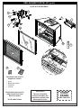
Robert H. Peterson Co. • 14724 East Proctor Avenue, • City of Industry, CA 91746
IMPORTANT
Remove all packing
material (including any
protective coatings) and
discard prior to use.
Your direct vent insert is
shipped in 4 boxes:
• Insert
• Refractory panels
• Surround
• Log set
Replacement parts can be
ordered from your local
Real Fyre dealer.
D1-30 model shown
SHARP
EDGES
USE CAUTION
REPLACEMENT PARTS LIST (cont.)
D1-30 & D1-36 MODELS
OFF
ON
19
9
20
17
11
10
15
22
7
25 24
2
3
8
6
18
13
1
12
14

17
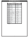
REPLACEMENT PARTS LIST (cont.)
D1-30 D1-36
Item Description Part No. Qty. Part No. Qty.
1. Control valve (Nat) D1-30-721 1 D1-30-721 1
or Control valve (LP) D1-30-722 1 D1-30-722 1
2. Front burner assembly D1-30-703 1 D1-36-703 1
3. Rear burner assembly D1-30-704 1 D1-36-704 1
4. Front burner orifi ce (Nat)* 3001-50-1 1 3001-48-1 1
or Front burner orifi ce (LP)* 3001-57-1 1 3001-57-1 1
5. Rear burner orifi ce (Nat)* 3001-45-1 1 3001-220-1 1
or Rear burner orifi ce (LP)* 3001-55-1 1 3001-150-1 1
6. Pilot assembly (Nat) D1-25-725 1 D1-25-725 1
or Pilot assembly (LP) D1-25-726 1 D1-25-726 1
7. Fan assembly D1-30-736 1 D1-30-736 1
8. Thermal disc sensor TS-3 1 TS-3 1
9. Grate D1-30-707 1 D1-36-707 1
10. Glass panel assembly D1-30-900 1 D1-36-900 1
11. Fine mesh barrier screen D1-30-913M 1 D1-36-913M 1
12. Fan HI/LO adjustment knob KNOB-11 1 KNOB-11 1
13. Igniter module OCR-34-21 1 OCR-34-21 1
14. Burner On/Off switch SW-9 1 SW-9 1
15. Lintel D1-30-902 1 D1-36-902 1
16. Spring door latch * D1-30-910 1 D1-30-910 1
17. Remote transmitter AT-R1-1 1 AT-R1-1 1
18. Remote receiver RR-1A 1 RR-1A 1
19. Ember screen D1-30-710 1 D1-30-710 1
20. Support leg (set of 4) D1-30-911 1 D1-30-911 1
21. Wire harness kit* WI-3 1 WI-3 1
22. Vent adapter plate D1-30-932 1 D1-30-932 1
23. Wire hook* D1-30-717 1 D1-30-717 1
24. Glowing embers EM-10 2 EM-10 2
25. Bryte coals EM-11 1 EM-11 2
*
Not shown

18
2
1
5
3
4
Burnt American Oak
Log Set Shown
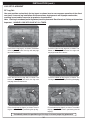
D1-30-2(A,S) Log Sets
Burnt American Oak Burnt Split American Oak
Item Description Part No. Qty. Part No. Qty.
1. Rear log D1AL-18BR 1 D1SL-18BR 1
2. Front logs D1AL-12BF 1 D1SL-12BF 1
3. Middle top log D1AL-11T 1 D1SL-11T 1
4. Right top log D1AL-18T 1 D1SL-18T 1
5. Middle left top log D1AL-13T 1 D1SL-13T 1
6. Left top log D1AL-9TL 1 D1SL-9TL 1
2
1
5
43
REPLACEMENT PARTS LIST (cont.)
D1-25-2(A,S) Log Sets
Burnt American Oak Burnt Split American Oak
Item Description Part No. Qty. Part No. Qty.
1. Rear log D1AL-17BR 1 D1AL-17BR 1
2. Front logs D1AL-10BF 1 D1SL-10BF 1
3. Middle top log D1AL-9TC 1 D1AL-9TC 1
4. Right top log D1AL-11TR 1 D1SL-11TR 1
5. Left top log D1AL-10TL 1 D1SL-10TL 1
Burnt American Oak
Log Set Shown
6

19
2
1
4
3
5
Burnt American Oak
Log Set Shown
6
D1-36-2(A,S) Log Sets
Burnt American Oak Burnt Split American Oak
Item Description Part No. Qty. Part No. Qty.
1. Rear log D1AL-21BRL 1 D1SL-21BRL 1
2. Front logs D1AL-13BF 1 D1SL-13BF 1
3. Middle log D1AL-11T 1 D1AL-11T 1
4. Right top log D1AL-18T 1 D1SL-18T 1
5. Middle top log D1AL-13T 1 D1SL-13T 1
6. Left top log D1AL-10T 1 D1SL-10T 1
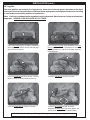
1
2
3
4
5
6
7
Boston brick panels shown
D1-25 D1-30 D1-36
Item Description Part No. Qty. Part No. Qty. Part No. Qty.
1. Left panel (Boston brick) D1-25-800 1 D1-30-800 1 D1-36-800 1
or Left panel (Herringbone) D1-25-801 1 D1-30-801 1 D1-36-801 1
2. Right panel (Boston brick) D1-25-802 1 D1-30-802 1 D1-36-802 1
or Right panel (Herringbone) D1-25-803 1 D1-30-803 1 D1-36-803 1
3. Rear panel (Boston brick) D1-25-804 1 D1-30-804 1 D1-36-804 1
or Rear panel (Herringbone) D1-25-805 1 D1-30-805 1 D1-36-805 1
4. Top panel (Boston brick) D1-25-806 1 D1-30-806 1 D1-36-806 1
or Top panel (Herringbone) D1-25-807 1 D1-30-807 1 D1-36-807 1
5. Left fl oor panel D1-25-808 1 D1-30-808 1 D1-30-808 1
6. Right fl oor panel D1-25-809 1 D1-30-809 1 D1-30-809 1
7. Front fl oor panel D1-25-810 1 D1-30-810 1 D1-36-810 1
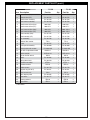
REPLACEMENT PARTS LIST (cont.)

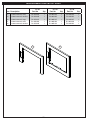
20
REPLACEMENT PARTS LIST (cont.)
D1-25 D1-30 D1-36
Item Description Part No. Qty. Part No. Qty. Part No. Qty.
1. 3 sided surround, small D1-25M-4A 1 D1-30M-4A 1 D1-36M-4A 1
or 3 sided surround, medium D1-25M-4B 1 D1-30M-4B 1 D1-36M-4B 1
or 3 sided surround, large D1-25M-4C 1 D1-30M-4C 1 D1-36M-4C 1
2. 4 sided surround, small D1-25M-4M 1 D1-30M-4M 1 D1-36M-4M 1
or 4 sided surround, medium D1-25M-4N 1 D1-30M-4N 1 D1-36M-4N 1
1
2

21
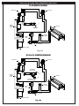
INSTALLATION REQUIREMENTS
Installation must be done by a qualifi ed professional service technician.
Prior to installation ensure that all specifi cations, dimensions, and minimum clearances stated in this
manual are observed. You must read all warnings and safety information, and understand all of the
information in this manual. All of these installation requirements must be observed and met.
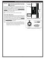
FIREPLACE REQUIREMENTS
A. This appliance must be vented directly to the outside in accordance with the current edition of the National
Fuel Gas Code (NFPA 54 in U.S.A. and CAN/CSA B149.1 in Canada) and must never be attached to a
chimney serving a separate solid fuel burning appliance. This appliance is designed to be installed into an
existing masonry fi replace (built to UBC 37 or ULC S628 standards) or factory built solid fuel, wood, burning
fi replace (listed to UL 127 or ULC S610) only. All exhaust gases must be vented outside the structure.
Combustion air is drawn from outside the structure.
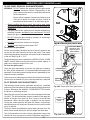
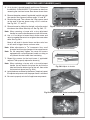
B. Cutting any sheet metal parts of the fi replace in which the gas fi replace insert is to be installed is prohibited,
with the exception of the fi rebox fl oor. The metal fi rebox fl oor may be removed/altered to allow additional
room for installation of the insert. Note: a minimum 2" clearance is required between the fi replace fl oor and
the insert. The clearance may be provided by lowering the fi rebox fl oor, placing bricks, etc. See Fig. 21-2.
C. If the factory-built fi replace has no gas access hole(s) provided, an access hole of 1.5 in (37.5 mm) or less
may be drilled through the lower sides or bottom of the fi rebox in a proper workmanship like manner. This
access hole must be plugged with non-combustible insulation after the gas supply line has been installed.
Si le foyer préfabriqué ne comporte pas d’orifi ces d’amenée du gaz, un orifi ce d’au plus 37,5 mm (1,5 po)
peut être pratiqué, selon les règles de l’art, dans la partie inférieure des parois ou au fond de la chambre
de combustion. Cet orifi ce doit être obturé au moyen d’isolant incombustible une fois la conduite de gaz
en place.
D. The fi replace fl ue damper must be removed for installation of the gas fi replace insert.
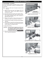
E. The fi replace and fi replace chimney must be completely clean. Brush and vacuum all interior surfaces so
that no embers, soot, or loose combustion deposits can be drawn into the heat circulation fan and blown
into the living area. The fi replace and fi replace chimney must be in good working order and constructed of
non-combustible materials. Inspect chimney clean-outs for proper fi t and seal. If any portion of the chimney
system shows signs of structural or mechanical weaknesses, the faulty portion must be repaired or replaced
prior to installing this appliance.
F. Refractory panels, glass panels, screen rails, screen mesh and log grates may be removed from the fi replace
(as needed) before installing the gas fi replace insert. Smoke shelves, shields and baffl es may be removed
if attached by mechanical fasteners. Any parts that are removed must be retained for later reinstallation to
restore the fi replace to its original operating condition. The removal of any part must not alter the integrity
of the outer shell of the pre-fab fi replace cabinet in any way. If any parts are removed (or altered) from the
existing fi replace, a Warning Label (see Fig. 21-1 below) must be affi xed inside the fi replace fi rebox. The
label must be visible upon removal of the direct vent insert.
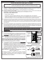
Fig. 21-1 Fireplace Warning Label
WARNING
THIS FIREPLACE HAS BEEN ALTERED
TO ACCOMODATE A FIREPLACE INSERT
AND SHOULD BE INSPECTED BY A QUALIFIED PERSON
PRIOR TO RE-USE AS A CONVENTIONAL FIREPLACE.
Fig. 21-2 Pre-fab fi replace fl oor height adjustment
Pre-fab
fi replace
Fireplace
fl oor
Insert resting
at new
lowered level
(i.e. lowering of
fl oor, placing
bricks, etc.)
Min. 2"
clearance
Combustible
fl oor

22
INSTALLATION REQUIREMENTS (cont.)
Fuel Type Minimum Normal Maximum
Natural 5" w.c. 7" w.c. 10.5" w.c.
Propane 10.5" w.c. 11" w.c. 13"w.c.
Fuel Type Low High
Natural 1.7" w.c. 3.5" w.c.
Propane 6.4" w.c. 10" w.c.
GAS PRESSURE REQUIREMENTS
A. The appliance and its appliance main gas valve must be disconnected from the gas supply piping system
during any pressure testing of that system at test pressures in excess of
1
/
2
psi (3.5 kPa).
The appliance must be isolated from the gas supply piping system by closing its equipment shutoff valve
during any pressure testing of the gas supply piping system at test pressures equal to or less than
1
/
2
psi
(3.5 kPa).
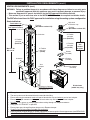
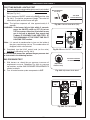
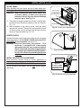
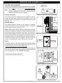
VENTING REQUIREMENTS
• Installation must be done by a qualifi ed professional service technician.
• This appliance is designed for installation into an existing masonry or factory-
built solid fuel burning fi replace.
• DO NOT make modifi cations to the system. DO NOT substitute or add
components other than those sold and/or approved by RHP.
• It is imperative that the appliance be installed EXACTLY as instructed in
this manual.
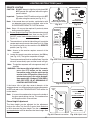
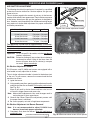
• It is imperative that the appliance be installed using only one of the
following RHP approved direct-vent fl ex kits (see Fig. 22-1):
Simpson Dura Vent
Co-Linear Kit w/ Flex: Kit w/ high-wind termination cap and two 3" x 35'
fl exible vent pipes - #46DVA-CL33
Bernard Dalsin
Proform Kit w/ Flex: Kit w/ high-wind termination cap and two 3" x 30' fl exible
vent pipes - #94203360HWS
Simpson Dura Vent
#46DVA-CL33
Fig. 22-1
RHP approved venting kits
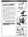
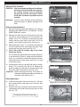
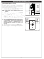
Incorrect Installation Methods
DO NOT use any of these methods, techniques, or products when installing the RHP Direct Vent
Insert System. Doing so may result in a malfunctioning appliance and may render it inoperable.
MAY CAUSE
OVERHEATING
REAR
WALL
DO NOT INSTALL
USING SHORT
STACK METHOD
(offset
shown for
clarity)
DO NOT VENT PIPES
OUT REAR WALL
(offset
shown for
clarity)
DO NOT RUN PIPES
HORIZONTALLY
NO
horizontal
run
(offset
shown for
clarity)
DO NOT CRIMP
OR RUPTURE
PIPES
DO NOT
USE THESE
PRODUCTS ON
PIPES:
• Mill-PAC
• Sealant/Silicone
(red or black)
DO NOT USE A
CORRUGATED
CHIMNEY LINER
DO NOT USE A
SHROUD
Bernard Dalsin
#94203360HWS
High-wind
termination
ONLY
Table 8 - Inlet Gas Supply Pressure
Table 9 - Manifold Gas Supply Pressure
Page is loading ...
Page is loading ...
Page is loading ...
Page is loading ...
Page is loading ...
Page is loading ...
Page is loading ...
Page is loading ...
Page is loading ...
Page is loading ...
Page is loading ...
Page is loading ...
Page is loading ...
Page is loading ...
Page is loading ...
Page is loading ...
Page is loading ...
Page is loading ...
Page is loading ...
Page is loading ...
Page is loading ...
Page is loading ...
Page is loading ...
Page is loading ...
Page is loading ...
Page is loading ...
Page is loading ...
Page is loading ...
Page is loading ...
Page is loading ...
Page is loading ...
Page is loading ...
Page is loading ...
Page is loading ...
-
 1
1
-
 2
2
-
 3
3
-
 4
4
-
 5
5
-
 6
6
-
 7
7
-
 8
8
-
 9
9
-
 10
10
-
 11
11
-
 12
12
-
 13
13
-
 14
14
-
 15
15
-
 16
16
-
 17
17
-
 18
18
-
 19
19
-
 20
20
-
 21
21
-
 22
22
-
 23
23
-
 24
24
-
 25
25
-
 26
26
-
 27
27
-
 28
28
-
 29
29
-
 30
30
-
 31
31
-
 32
32
-
 33
33
-
 34
34
-
 35
35
-
 36
36
-
 37
37
-
 38
38
-
 39
39
-
 40
40
-
 41
41
-
 42
42
-
 43
43
-
 44
44
-
 45
45
-
 46
46
-
 47
47
-
 48
48
-
 49
49
-
 50
50
-
 51
51
-
 52
52
-
 53
53
-
 54
54
-
 55
55
-
 56
56


Real Fyre D1 Operating instructions
- Category
- Fireplaces
- Type
- Operating instructions
- This manual is also suitable for
Ask a question and I''ll find the answer in the document
Finding information in a document is now easier with AI
Related papers
-
Real Fyre D2 Direct Vent Operating instructions
-
-
-
-
-
-
-
-
-
Other documents
-
Miele KM 3464 G Specification
-
 Lennox Hearth SHRL 33/40 DV INS User manual
-
Essence ESS45 Installation And Operating Instructions Manual
-
NAPOLEON SGM3F3B4 Owner's manual
-
Superior Fireplaces DRI2000 Operating instructions
-
R.H. Peterson G4-42 Owner's manual
-
Ashley Hearth Products AGDV12N Installation guide
-
-
 Lennox Hearth 33/40 DV INS User manual
-
 Mendota FV33i Installation & Operating Manual


