
Tel.: 1 (450) 444 2030 • Toll Free: 1-888-222-1560 • Fax: 1 (450) 444 2029 • Internet: www.kantech.com DN1781-0809
Copyright © 2008 Tyco International Ltd. and its Respective Companies. All Rights Reserved. • Specifications may change without notice.
Kantech and the Kantech logo are trademarks of Tyco International Ltd. and its Respective Companies.
KT-MOD-OUT16
KT-400 Expansion Module 16-Output with SPI Cable Install Sheet
1. Introduction
The KT-MOD-OUT16 is a 16 zones output module. It can be
used for elevator access control (may require additional
hardware).
The module supports daisy chaining; you can interconnect up to
16 KT-MOD-OUT16 modules for a total of 256 external outputs
per KT-400. You can mix relays and outputs in the same SPI
group, up to 256 outputs.
Note 1: The KT-400 SPI port maximum current draw, when the
12V AUX terminals are not used, is 500 mA.
Note 2: External power supply (12 VDC, 2 Amps) is required
when the total current draw exceeds 500mA on the SPI Port.
Note 3: There are already 4 relays available on the KT-400.
Make sure to check the relays number assignments to prevent
redundancy unless it has been planned on purpose.
2. Specifications
• Maximum Current draw: up to 750 mA per module
• Connects to the KT-400 via the 6-pin SPI connector
• 16 outputs low current module, 5 to 24 VDC, 4 to 750 mA
• Can be used for elevator access control or general output
• Can be mixed with output module KT-MOD-REL8 in the
same SPI group
3. Installing the KT-MOD-OUT16
3.1. Unpacking
The KT-MOD-OUT16 package includes the following parts:
• One (1) KT-MOD-OUT16 module, 14 cm x 8 cm (5.7 in x
3.25 in)
• One (1) SPI cable with 1 SPI connector, 41 cm (16 in)
• Four (4) plastic standoffs
• Two (2) installation sheets, English and French
3.2. Mounting
The KT-MOD-OUT16 can be installed inside a compatible cabinet
(KT-MOD-CAB or KT-400) or mounted in a dry and secure
location at less than 1 m (3 ft) from the KT-400.
Perform the following steps to mount the unit:
1. Press the four (4) plastic standoffs through the mounting
holes of the cabinet,
2. Secure the cabinet to the wall in the desired location. Use
appropriate wall anchors when securing the cabinet to
drywall, plaster, concrete, brick or other surfaces,
3. Press the module into the plastic standoffs to secure the
module to the cabinet.
Once the unit is mounted, wiring may be started.
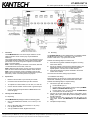
3.3. Installation and Wiring
Before beginning to wire the unit, ensure that all power (AC
transformer and battery) is disconnected from the KT-400.
Perform the following steps to complete wiring:
1. Connect the 6-pin SPI connector to:
• the KT-400 SPI port, or
• the SPI OUT of the previous output module (KT-MOD-
REL8 and KT-MOD-OUT16 only), or
• the SPI EXP of the 1st input module KT-MOD-INP16
connected to the KT-400 SPI port.
2. Connect the six SPI wires (blue (BLU), white (WHT), green
(GRN), yellow (YEL), black (BLK) and red (RED)) to the SPI
IN (TB1) terminals.
3. Connect the 6-pin SPI connector from the SPI OUT to the
next output module (KT-MOD-REL8 and KT-MOD-OUT16
only).
4. Complete all output wiring.

Tel.: 1 (450) 444 2030 • Toll Free: 1-888-222-1560 • Fax: 1 (450) 444 2029 • Internet: www.kantech.com DN1781-0809
Copyright © 2008 Tyco International Ltd. and its Respective Companies. All Rights Reserved. • Specifications may change without notice.
Kantech and the Kantech logo are trademarks of Tyco International Ltd. and its Respective Companies.
KT-MOD-OUT16
KT-400 Expansion Module 16-Output with SPI Cable Install Sheet
3.4. Check the power jumper JP1 position. Put it on EXT if you
need external power or INT if no external power is required.
3.5. Applying Power
After all wiring is completed, connect the 16 VAC to the KT-400.
Connect the battery leads to the battery, and then apply power to
the AC transformer.
Note: Do not connect the power until all wiring is complete.
Terminal Connections
Module no.: ______________________________________________________________________________________
Date of installation: _______________________________________________________________________________
KT-400 Name: ____________________________________________________________________________________
KT-400 SITE NAME: _______________________________________________________________________________
KT-400 Serial Number: _____________________________________________________________________________
AUX: ___________________________________________________________________________________________
SPI BUS (FROM): _________________________________________________________________________________
SPI BUS (TO): ____________________________________________________________________________________
F O1:
F O9: _________________________________________
F O2:
F O10: ________________________________________
F O3:
F O11: ________________________________________
F O4:
F O12: ________________________________________
F O5:
F O13: ________________________________________
F O6:
F O14: ________________________________________
F O7:
F O15: ________________________________________
F O8:
F O16: ________________________________________
FCC & IC COMPLIANCE STATEMENT
CAUTION: Changes or modifications not expressly approved by Kantech could void your authority to use this equipment.
This equipment generates and uses radio frequency energy and if not installed and used properly, in strict accordance with the manufacturer’s instructions,
may cause interference to radio and television reception. It has been type tested and found to comply with the limits for Class A device in accordance with
the specifications of Part 15 of FCC Rules, which are designed to provide reasonable protection against such interference in any residential installation.
However, there is no guarantee that interference will not occur in a particular installation. If this equipment does cause interference to television or radio
reception, which can be determined by turning the equipment off and on, the user is encouraged to try to correct the interference by one or more of the
following measures:
•
Re-orient the receiving antenna
•
Relocate the alarm control with respect to the receiver
•
Move the alarm control away from the receiver
•
Connect the alarm control into a different outlet so that alarm control and receiver are on different circuits.
If necessary, the user should consult the dealer or an experienced radio/television technician for additional suggestions. The user may find the following
booklet prepared by the FCC helpful: “How to Identify and Resolve Radio/Television Interference Problems”. This booklet is available from the U.S.
Government Printing Office, Washington, D.C. 20402, Stock # 004-000-00345-4. This device complies with Part 15 of the FCC rules. Operation is subject to
the following two conditions: (1) this device may not cause harmful interference, and (2) this device must accept any interference received including
interference that may cause undesired operation. This Class A digital apparatus meets all requirements of the Canadian Interference Causing Equipment
Regulations. The KT-400 is also compliant with EN55022: 1994, amendment 1: 1995, Class A.
-
 1
1
-
 2
2


Ask a question and I''ll find the answer in the document
Finding information in a document is now easier with AI
Related papers
Other documents
-
 American Dynamics KT-400 User manual
-
 American Dynamics Expansion Modules Cabinet KT-MOD-CAB User manual
-
 American Dynamics KT-400 User manual
-
Johnson Controls Tyco Kantech KT-MOD-IO16 Installation guide
-
 Kantech KT-PC4204 User manual
-
 Kantech P345KPMTR Installation guide
-
 KANTECH TYCO Kantech Smart Reader Multi Tech Technical Manual
-
AMX AXC-REL8 8 RELAY CARD Quick start guide
-
 Kantech KT-1 Installation guide
-


