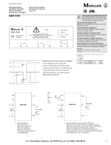
Eaton IZM-STS Operating instructions

Type
Operating instructions

This manual is also suitable for

Eaton IZM-STS is a shunt trip that can be installed in low voltage circuit breakers. It opens the circuit breaker when its coil is energized by a voltage input. It is used to remotely trip a circuit breaker in case of an emergency, such as a fire or electrical fault. The shunt trip is easy to install and can be mounted on either the left or right side of the circuit breaker. It comes with a cut-off switch that isolates the shunt trip from the circuit breaker when it is not in use. The shunt trip is compatible with all IZM series circuit breakers.

Here are some of the benefits of using the Eaton IZM-STS shunt trip:

Effective May 2010 2C15995H03
05/10 AWA1230-2441
Shunt trip in IZM
low voltage circuit breakers
warning
(1) Only qualified electrical persOnnel shOuld
be permitted tO wOrk On the equipment.
(2) always de-energize primary and
secOndary circuits if a circuit breaker
cannOt be remOved tO a safe wOrk lOcatiOn.
(3) drawOut circuit breakers shOuld be
levered (racked) Out tO the discOnnect
pOsitiOn.
(4) all circuit breakers shOuld be switched
tO the Off pOsitiOn and mechanism springs
discharged.
failure tO fOllOw these steps fOr all
prOcedures described in this instructiOn
leaflet cOuld result in death, bOdily injury,
Or prOperty damage.
warning
the instructiOns cOntained in this awa and On
prOduct labels have tO be fOllOwed. Observe
the five safety rules:
– discOnnecting
– ensure that devices cannOt be
accidentally restarted
– verify isOlatiOn frOm the supply
– earthing and shOrt-circuiting
– cOvering Or prOviding barriers tO
adjacent live parts
discOnnect the equipment frOm the supply.
use Only authOrized spare parts in the repair
Of the equipment. the specified maintenance
intervals as well as the instructiOns fOr
repair and exchange must be strictly adhered
tO prevent injury tO persOnnel and damage tO
the switchbOard.
Section 1: General information
The shunt trip opens the circuit breaker when
its coil is energized by a voltage input. When
replacing a shunt trip, both the shunt trip and
the cut-off switch must be replaced.
Section 2: Installation of the
shunt trip
To install the shunt trip, proceed with the
following eight steps:
Step 1: Remove the front cover by unscrewing
the hex-head captive bolts (four for three-pole,
six for four-pole) that join the cover to the breaker
housing using a 10 mm 1/4-inch drive socket.
Then hold the charge handle down approximately
45 degrees to pull off the cover.
Step 2: Place the appropriate label on the
front cover nameplate space located under
“Accessories.”
Figure 1. Steps 1 and 2
Step 3: Each shunt trip comes with a cut-off
switch. Mount the switch by sliding the lock to
the unlocked (up) position. Install the hook feet
down through openings as shown. Then slide
the assembly forward so the hook feet engage
the mounting plate. Slide the lock down into the
locked position.
ote:N The cut-off switch is not applicable for the
continuous duty shunt trip.
Bolt
Label
Shunt trip in IZM
low voltage circuit breakers
Eaton Industries GmbH
Electrical Sector
©2010 by Eaton Industries GmbH
Änderungen vorbehalten
Subject to alterations
05/10 AWA1230-2441 / Z8693
Moon/Doku/Heng
Printed in USA (05/10)
05/10 AWA1230-2441
Effective May 2010
Figure 2. Step 3
Step 4: Slide the lock on the shunt trip to the unlocked (up) position,
and install the hook feet down through the opening. Then slide it
forward until the feet engage the mounting plate. Slide the lock back
down to lock the shunt trip in place.
Figure 3. Step 4
Step 5: Mate the shunt trip connector with the cut-off switch
connector.
Figure 4. Step 5
Shunt Trip
Cut-Off Switch
Forward
Lock
Hook Feet
Mounting
Plate
Shunt Trip
Forward
Lock
Hook Feet
Mounting Plate Mount First
Shunt Trip Here
B11 B10 Mated Connector
Shunt Trip
Cut-Off
Switch
Mounting
Plate
Shunt Trip
Step 6: Wire to the secondary contact block “B,” positions 10 and
11 in keeping with the wire markings.
Figure 5. Step 6
Step 7: If a second shunt trip is to be installed, repeat Steps 3, 4,
and 5. Wire to the secondary contact block “A,” positions 7 and 8.
Figure 6. Step 7
Step 8: Reinstall front cover removed in Step 1.
Secondary
Block “A”
Secondary
Block “B”
Mounting
Plate
First Shunt Trip
Cut-Off Switch
Here
Mounting
Plate
First
Shunt Trip
Install Second
Shunt Trip
Here
Install
Second Shunt
Trip Cut-Off
Switch Here
Gültig ab Mai 2010 2C15995H03
05/10 AWA1230-2441
Arbeitsstromauslöser
IZM-ST…/IZM-STS
Warnung
(1) Die instanDhaltung Darf nur Durch
entsprechenD elektrontechnisch
qualifiziertes personal erfolgen.
(2) Vor Beginn Der arBeiten muss Der
spannungsfreie zustanD Der schaltanlage
hergestellt unD WährenD Der arBeiten
sichergestellt sein.
(3) schalter in ausfahrtechnik müssen
in trennstellung gefahren WerDen.
(4) Die schalter sinD auf aus zu stellen
unD Der feDerspeicher ist zu entspannen.
Beim BetrieB elektrischer geräte stehen
zWangsläufig Bestimmte teile Dieser
geräte unter gefährlicher spannung.
unsachgemäßer umgang mit Diesen geräten
kann DeshalB zu toD oDer schWeren
körperVerletzungen soWie erheBlichen
sachschäDen führen.
Warnung
Beachten sie Bei instanDhaltungsmaßnahmen
an Diesem gerät alle in Dieser aWa unD auf
Dem proDukt selBst aufgeführten hinWeise.
Die fünf sicherheitsregeln sinD einzuhalten:
– freischalten
– gegen WieDereinschalten sichern
– spannungsfreiheit feststellen
– erDen unD kurzschließen
– BenachBarte, unter spannung stehenDe
teile aBDecken oDer aBschranken
Das gerät ist Vom netz zu trennen. es Dürfen
nur Vom hersteller zugelassene ersatzteile
VerWenDet WerDen. Die VorgeschrieBenen
WartungsinterValle soWie Die anWeisungen
für reparatur unD austausch sinD unBeDingt
einzuhalten, um schäDen an personen unD
anlagen zu VermeiDen.
Abschnitt 1: Allgemeine
Informationen
Der Arbeitsstromauslöser öffnet den
Leistungsschalter wenn die Spule des
Arbeitsstromauslösers unter Spannung
gesetzt wird. Wenn der Arbeitsstromauslöser
ausgetauscht wird, dann müssen sowohl der
Arbeitsstromauslöser wie auch der dazugehörige
Trennschalter ausgetauscht werden.
Abschnitt 2: Einbau des
Arbeitsstromauslösers
Führen Sie die folgenden Schritt aus:
Schritt 1: Schrauben Sie die Halteschrauben von
der Frontabdeckung ab. Drücken Sie nun den
Antriebshandhebel herunter (ca. 45°) um
die Frontabdeckung abzunehmen.
Schritt 2: Kleben Sie den beiliegenden
Typenaufkleber auf die entsprechende Stelle
des Typenschildes.
Abbildung 1. Steps 1 und 2
Schritt 3: Jeder Arbeitsstromauslöser wird mit
einem Trennschalter ausgeliefert. Um diesen zu
montieren, schieben Sie den Sperrschieber nach
oben. Setzen Sie die Füße des Abstellschalters in
die Öffnungen. Schieben Sie den Abstellschalter
in die Arretierung und verrasten Sie den
Sperrschieber.
nmerkung:A Der Trennschalter ist nicht geeignet für
Arbeitsstromauslöser mit 100 % ED.
Schraube
Etikett
Arbeitsstromauslöser
IZM-ST…/IZM-STS…
Eaton Industries GmbH
Electrical Sector
©2010 by Eaton Industries GmbH
Änderungen vorbehalten
Subject to alterations
05/10 AWA1230-2441 / Z8693
Moon/Doku/Heng
Printed in USA (05/10)
05/10 AWA1230-2441
Gültig ab Mai 2010
Abbildung 2. Schritt 3
Schritt 4: Schieben Sie den Sperrschieber nach oben. Setzen Sie
die Füße des Arbeitsstromauslösers in die Öffnungen. Schieben
Sie den Arbeitsstromauslöser in die Arretierung und verrasten Sie
den Sperrschieber.
Abbildung 3. Schritt 4
Schritt 5: Verbinden Sie die Stecker des Arbeitsstromauslösers und
des Trennschalters miteinander.
Abbildung 4. Schritt 5
Trennschalter
Einsetzen und
einrasten
Sperrschieber
entsperren
Füße
Befestigungsplatte
Arbeitsstromauslöser
Einsetzen und
einrasten
Sperrschieber
entsperren
Füße
Befestigungsplatte Position erster
Arbeitsstromauslöser
B11 B10 Verbundene Stecker
Trennschalter
Befestigungsplatte
Arbeitsstromauslöser
Schritt 6: Verbinden Sie die Kabel mit den Positionen 10 und 11 am
Steuerleitungsanschluss B (wie auf den Kabeln angegeben).
Abbildung 5. Schritt 6
Schritt 7: Wenn ein zweiter Arbeitsstromauslöser eingebaut werden
soll, wiederholen sie Schritt 3, 4 und 5 und verbinden Sie die Kabel
mit den Positionen 7 und 8 am Steuerleitungsanschluss A.
Abbildung 6. Schritt 7
Schritt 8: Schrauben Sie die Frontabdeckung wieder an.
Steuerleitungsanschluss A Steuerleitungsanschluss B
Befestigungsplatte
Position erster
Trennschalter
Position erster
Arbeitsstromauslöser
Befestigungsplatte
Position zweiter
Arbeitsstromauslöser
Position zweiter
Trennschalter
  • Page 1 1
  • Page 2 2
  • Page 3 3
  • Page 4 4

Eaton IZM-STS Operating instructions

Type
Operating instructions
This manual is also suitable for

Eaton IZM-STS is a shunt trip that can be installed in low voltage circuit breakers. It opens the circuit breaker when its coil is energized by a voltage input. It is used to remotely trip a circuit breaker in case of an emergency, such as a fire or electrical fault. The shunt trip is easy to install and can be mounted on either the left or right side of the circuit breaker. It comes with a cut-off switch that isolates the shunt trip from the circuit breaker when it is not in use. The shunt trip is compatible with all IZM series circuit breakers.

Here are some of the benefits of using the Eaton IZM-STS shunt trip:

Ask a question and I''ll find the answer in the document

Finding information in a document is now easier with AI

in other languages