
Witty
1 / 36 30.01.2019
Station de Charge
Elektrofahrzeug Ladestation
Charging station
Hager witty.eco & witty.premium
Notice d’installation /
Installationsanleitung /
Installation manual
Version 4.5.3
6LE003319D
Page is loading ...
Page is loading ...

Witty
4 / 36
Contents
1 General description of charging station ............................................................... 6
2 Removing the enclosure cover ............................................................................ 6
2.1 Electrical components of charging station ..................................................... 7
3 Electrical installation ............................................................................................ 8
3.1 Protection ...................................................................................................... 8
3.2 Quality of earthing ......................................................................................... 9
3.3 Connection terminals ..................................................................................... 9
3.4 Detection of welded contactor contacts ......................................................... 9
4 Fixation and connection ..................................................................................... 10
4.1 Drilling scheme, mounting basic wall fixation .............................................. 10
4.2 Mounting basic wall fixation ......................................................................... 11
4.3 Scheme for ground mounting XEV418/19 + XEV420* ................................. 11
4.4 Electrical supply........................................................................................... 12
5 Configuration of charging station ....................................................................... 13
5.1 Maximum charge current ............................................................................. 13
5.2 Immediate or postponed charging .............................................................. 13
5.3 Postponed charging ..................................................................................... 14
5.4 Dynamic charging ........................................................................................ 15
6 Managing user authentications .......................................................................... 15
6.1 Local authentication ..................................................................................... 16
6.2 Online user authentication ........................................................................... 17
7 Establish online connection ............................................................................... 17
8 Configuration of charge controller ..................................................................... 19
8.1 User authentication local or online ............................................................... 19
8.2 Initiating start of charge by external signal .................................................. 20
8.3 Demand reduction by stop of charge ........................................................... 22
8.4 Configuration of bidirectional communication .............................................. 24
8.4.1 Remote connection to charging station ................................................. 24
8.4.2 Connection to a router .......................................................................... 25
8.4.3 Connection to a GPRS modem with fixed IP......................................... 27
8.4.4 Connection to an ADSL or GPRS modem with dynamic IP .................. 30
8.4.5 Remote connection to server ................................................................ 31
9 Malfunction ........................................................................................................ 32
10 Electrical Maintenance .................................................................................... 33
11 Technical characteristics................................................................................. 34
12 Correct Disposal of this product ...................................................................... 34

Witty
5 / 36
Précautions initiales
Erste Vorsichtsmaßnahmen
Initial precautions

Witty
6 / 36
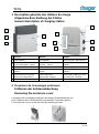
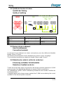
1 Description générale des stations de charge
1 Allgemeine Beschreibung der Station
1 General description of charging station
français
deutsch
english
1
Prise Mode 3 Type 2S
(verrouillable)
Ladesteckdose Mode 3,
(verriegelbar)
Socket Mode 3 with interlock
2
Prise Mode 2
(Prise domestique - option)
Ladesteckdose Mode 2
(Schuko - option)
Standard socket
(option)
3
Rangement fiche
Steckerlager
Plug Storage
4
Lecteur Carte RFID
(option)
RFID Kartenleser
(option)
RFID card reader
(option)
5
Bouton poussoir
(Marche forcée en cas de
départ de charge différé)
Taster
(Sofort-start wenn
Zeitversetzte Ladung)
Push Button
(Immediate charging in case
of Postponed charging)
6
Bandeau lumineux
LED Anzeige
LED display
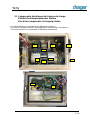
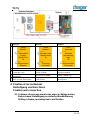
2 Ouverture de l’enveloppe extérieure
2 Entfernen der Gehäuseabdeckung
2 Removing the enclosure cover
L’ouverture de l’enveloppe extérieure se fait par l’intermédiaire de vis /
Zum Entfernen der Gehäuseabdeckung werden Schrauben gelöst /
The enclosure cover can be removed by releasing screws
1
2
3
4
5
6
5
6
3
1
2
Page is loading ...

Witty
8 / 36
français
deutsch
english
1
Détection Contact collé
Contacteur selon le modèle
Erkennung verklebter
Schützkontakte, je nach
Ausführung
Detection of welded
contactor contacts,
depending on the model
2
Prise M3T2S (verrouillable)
M3T2S Ladesteckdose
(veriegelbar)
M3T2S socket with
interlock
3
Prise M2TE
M2TE Ladesteckdose
M2TE socket
4
Plaque Passe Câbles
Kabelführung
Cable management
5
Controleur
Ladecontroller
charge controller board
6
Carte TCP/IP
TCP/IP Karte
TCP/IP card
7
Alimentation électronique
Elektronikstromversorgung
Electronic power supply
8
Contacteurs + Disjoncteurs
Schütz + Leistungsschalter
Contactors + breakers
9
Borniers de raccordement
Reihenklemmen
Terminals
3 Installation électrique
3 Elektrische Installation
3 Electrical installation
3.1 Protections
3.1 Absicherung
3.1 Protection

Witty
9 / 36
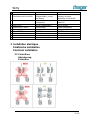
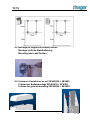
3.2 Qualité de la mise à la terre
3.2 Qualität der Erdung
3.3 Quality of earthing
français
deutsch
english
1
100 maxi pour les 10
bornes
Max. 100 für 10 Stationen
Max. 100 for 10 stations
2
10 bornes max sur 1 terre
Max. 10 Stationen auf 1
Erdung
Max. 10 stations on 1
earthing
3
Interconnexion
Zusammenschaltung
Interconnection
3.3 Bornes de raccordement
3.4 Anschlussklemmen
3.2 Connection terminals
Les bornes de raccordement au réseau sont prévues pour des câbles de diamètre
flexible 10mm
2
(16 mm
2
) /
Die Netzanschlussklemmen sind für flexibel10mm
2
(starr 16 mm
2
) ausgelegt /
The connection terminals are suitable for flexible 10mm
2
(rigid 16 mm
2
)
3.4 Détection de contacts collés du contacteur
Erkennung verklebter Schützkontakte
3.3 Detection of welded contactor
Toutes les bornes witty ayant une puissance de charge nominale supérieure à 3,6kW
sont pourvues d’un dispositif de détection de contact collé du contacteur /
Die Ladestationen größer 3,6kW Ladeleistung überwachen die korrekte Funktion der
Leistungsschütze /
Charging stations with charge powers greater than 3,6kW are monitoring the correct
operation of the internal power contactors
OK
NOK
REGIME DE
NEUTRE /
NETZFORM /
EARTHING
SYSTEM
IT
1 System
REGIME DE NEUTRE / NETZFORM /
EARTHING SYSTEM
TN / TT
2
max.
100
3
1

Witty
10 / 36
français
deutsch
english
1
2
Bobine À Emission MZ203
Arbeitsstromauslöser MZ203
Shunt trip MZ203
3
Déconnexion Réseau Si
Contacteur collé
Trennung vom Netz, falls der
Schütz verklebt
Disconnection from grid if
contactor welded
4
Puissance > 4kVA
uniquement
Nur Leistung > 4kVA
Power > 4kVA only
5
Protection intégrée
Dans la carte électronique
Integrierter Schutz
in der Platine
Integrated protection
in the board
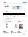
4 Fixation et raccordement
4 Befestigung und Anschluss
4 Fixation and connection
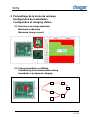
4.1 Schémas de perçage mural sans espace câblage arrière
4.1 Bohrschema, Befestigung an einfache Wandhalterung
4.1 Drilling scheme, mounting basic wall fixation
error
detected
Constant
red warning
light
3s
Disconnection
From grid
Fehler
erkannt
Konstant rote
Warnleuchte
3s
Trennung
vom Netz
Défaut
détecté
Information
Voyant
Rouge Fixe
3s
Déconnexion
Réseau

Witty
11 / 36
4.2 Montage du support de fixation murale
4.2 Montage einfache Wandhalterung
4.2 Mounting basic wall fixation
4.3 Schémas d’installation au sol XEV418/19 + XEV420
4.3 Schema zur Bodenmontage XEV418/19 + XEV420
4.3 Scheme for ground mounting XEV418/19 + XEV420*

Witty
12 / 36
français
deutsch
english
1
Zone de Fixation Borne
Befestigungsbereich des
Systems
System attachement zone
2
Fondation C20/25, X0
Profondeur 80cm
Fundament C20/25, X0
Tiefe 80cm
Foundation C20/25, X0
Depth 80cm
3
Couche de Propreté 5cm,
C8/10
Unterlagerschicht 5cm,
C8/10
Subbase 5cm, C8/10
4.4 Alimentation électrique
4.4 Elektrische Versorgung
4.4 Electrical supply
français
Deutsch
english
1
Borniers Puissance 10mm
2
maxi - rigide 16mm
2
Leistungsklemmen max.
10mm
2
- massiv 16mm
2
Power terminals max. 10mm
2
- massiv 16mm
2
Page is loading ...

Witty
14 / 36
français
deutsch
english
1
Charge immédiate
Sofortladung
Immediate charging
2
Autorisation immédiate
Sofortige Autorisierung
Immediate authorization
3
Charge différée
Zeitversetze Ladung
Postponed charging
4
Signal Tarif de Nuit
du comteur
Nachtstromsignal
vom Zähler
Night tariff signal
from main meter
5
Autorisation conditionnée
Bedingte Freischaltung
durch ext. Signal
Conditional authorization
6
Charge VE
Laden des EV
Charging EV
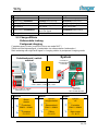
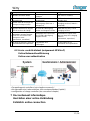
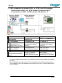
5.3 Charge différée
5.3 Zeitversetzte Ladung
5.3 Postponed charging
Compteur avec Entrée Jour/Nuit + Borne en mode NUIT /
Zähler mit Nachtstromsignal + Ladestation im zeitversetzten Lademodus /
Main metering with night tariff signal + charging station in postponed charging mode
français
deutsch
english
1
Contrôleur /
Steuereinheit /
Controller
Armoire électrique /
Schaltschrank / switch
cabinet
System
Câble / Kabel / Cable 2x1,5 mm
2
Borne /
Klemmen /
Terminals
50 & 51 bei XEV2XX
60 & 61 bei XEV1XX
Borne / 230V AC Signal/
Terminals C1 & C2
Borne
éteinte
Controleur
50&51 / 60&61
Compteur
C1 & C2
System
ausgeschaltet
Steuereinheit
50&51 / 60&61
Zähler
C1 & C2
System
off
Controller
50&51 / 60&61
Main meter
C1 & C2
1

Witty
15 / 36
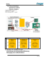
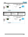
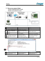
5.4 Charge dynamique
5.4 Dynamische Ladung
5.4 Dynamic charging
Compteur avec Protocol TIC
Zähler mit TIC signal
Main metering with TIC signal
français
deutsch
english
1
6 Gestion du contrôle d’accès
6 Einstellung der Nutzerauthentifizierung
6 Managing user authentications
Borne
éteinte
Controleur
53&54 / 63&64
Compteur
I1 & I2
System
ausgeschaltet
Steuereinheit
53&54 / 63&64
Zähler
I1 & I2
System
off
Controller
53&54 / 63&64
Main meter
I1 & I2
Borne /
Klemmen /
Terminals
53 & 54 bei XEV2XX
63 & 64 bei XEV1XX

Witty
16 / 36
6.1 Accès contrôlé local
6.1 Lokale Authentifizierung
6.1 Local authentication
français
deutsch
english
1
Clé USB
(livrée uniquement avec XEV2xx)
USB-Stick
(nur mit XEV2xx geliefert)
USB stick
(only delivered with XEV2xx)
2
Transférer via clé USB
Übertragung
mit dem USB-Stick
Transfer via USB stick
3
Technologies :
Mifare 1k ou 4k
Mifare Ultralight NTAG203
Technologien:
Mifare 1k oder 4k
Mifare Ultralight NTAG203
Technologies :
Mifare 1k or 4k
Mifare Ultralight NTAG203
+ Paramétrage du contrôleur (voir chapitre concerné) /
+ Konfiguration des Ladecontrollers (siehe entsprechendes Kapitel) /
+ Configuration of charge controller (see concerned chapter)
1
2
3
4
5
6

Witty
17 / 36
français
deutsch
english
1
Numéro d’ordre à définir
Reihenfolge der Nummern
festlegen
Set order of numbers
2
Numéro de la Carte RFID en
Hexadécimal
RFID-Kartennummer in
Hexadezimal
RFID card number in
hexadecimal
3
Durée maxi de la session de
charge (si vierge = infini)
Maximale Dauer eines
Ladevorgangs (falls leer =
unbegrenzt)
Maximum duration of
charging session (if blank =
unlimited)
4
Déclaration des utilisateurs
pouvant démarrer et stopper
LEUR session de charge
Deklaration der Nutzer, die
nur IHREN Ladevorgang
starten und stoppen können
Declaration of users that can
start and stop only THEIR
charging session
5
Déclaration des super-
utilisateurs pouvant stopper
TOUTES les sessions de
charge en cours
(permanent, surveillant)
Deklaration der Super-User,
die JEDEN Ladevorgang
stoppen können
Declaration of super users
that can stop ANY charging
session
(permanent, supervisor)
6
À droite du signe # = zone de
commentaire et d’explication
Rechts eines # =
Kommentare und
Erklärungen
To the right of a # =
comments and explanations
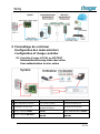
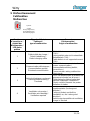
6.2 Accès contrôlé distant (uniquement XEV2xxC)
6.2 Online Nutzerauthentifizierung
6.2 Online user authentication
+ Paramétrage du contrôleur (voir chapitre concerné) /
+ Konfiguration des Ladecontrollers (siehe entsprechendes Kapitel) /
+ configuration of charge controller (see concerned chapter)
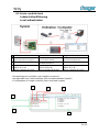
7 Raccordement informatique
7 Herstellen einer online Verbindung
7 Establish online connection

Witty
18 / 36
français
deutsch
english
1
Communication
Bidirectionelle:
Ouverture port nécessaire
Routage Adresse IP à définir
Bidirektionale
Kommunikation:
Portöffung notwendig
Routing-IP-Adresse festlegen
Bidirectional communication:
Port opening necessary
Set Routing IP address

Witty
19 / 36
8 Paramétrage du contrôleur
8 Konfiguration des Ladecontrollers
8 Configuration of charge controller
8.1 Contrôle d’accès LOCAL ou DISTANT
8.1 Nutzerauthentifizerung lokal oder online
8.1 User authentication local or online
français
deutsch
english
1
Clé USB
(livrée uniquement avec XEV2xx)
USB-Stick
(nur mit XEV2xx geliefert)
USB stick
(only delivered with XEV2xx)
2
Transférer via clé USB
Übertragung
mit dem USB-Stick
Transfer via USB stick
3
Accés controlé LOCAL
Nutzerauthentifizierung
LOKAL
User authentification LOCAL
4
Accés controlé DISTANT
Nutzerauthentifizierung
ONLINE
User authentification
ONLINE

Witty
20 / 36
Fichier/Datei/file << bxxxx config.cfg >> ou/oder/or << bxxxx global.cfg >>
français
deutsch
english
0
sans contrôle, home version
Ohne Nutzerauthentifizierung
Free of charge
1
Contrôle d’accès LOCAL
Nutzerauthentifizierung
LOKAL
User authentification LOCAL
2
Contrôle d’accès DISTANT
Nutzerauthentifizierung
ONLINE
User authentification
ONLINE
3
À droite du signe # = zone de
commentaire et d’explication
Rechts eines # =
Kommentare und
Erklärungen
To the right of a # =
comments and explanations
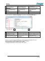
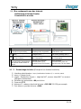
8.2 Démarrage différé de charge par signal extérieur
8.2 Ladestart mittels externem Freischaltsignal
8.2 Initiating start of charge by external signal
français
deutsch
english
1
Clé USB
(livrée uniquement avec XEV2xx)
USB-Stick
(nur mit XEV2xx geliefert)
USB stick
(only delivered with XEV2xx)
2
Transférer via clé USB
Übertragung
mit dem USB-Stick
Transfer via USB stick
1
2
3
PIN65 (XEV2…)
PIN42 (XEV1…)

Witty
21 / 36
3
Prise en compte
Signal extérieur de
démarrage
Berücksichtigung eines
Externen Startsignals
Consideration of
External starting signal
4
Signal extérieur
Co-Génération Horloge
24VDC
Externes Signal vom
Blockheizkraftwerk
24VDC
External signal from
Cogeneration unit
24VDC
5
Glissière
Schiebeschalter
Slide switch
6
Bornier Entrées
Klemmeneingänge
Terminal board inputs
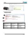
Fichier/Datei/file << bxxxx config.cfg >> ou/oder/or << bxxxx global.cfg >>
français
deutsch
english
1
0 = Signal extérieur de
Démarrage de charge
0 = Externes Signal zum
Starten des Ladevorgangs
0 = External signal to
Start the charging session
2
À droite du signe # = zone de
commentaire et d’explication
Rechts eines # =
Kommentare und
Erklärungen
To the right of a # =
comments and explanations
Dans ce cas, toute charge commencée suite à l’apparition du signal 24V sera
terminée, même si le 24V signal extérieur n’est plus activé /
Ladung startet bei aktivem externen 24V Signal /
Charging will start with an active external 24V signal
1
2

Witty
22 / 36
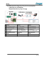
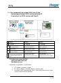
8.3 Effacement de charge lors d’un pic de consommation
8.3 Ladestopp zur Lastreduktion
8.3 Demand reduction by stop of charge
français
deutsch
english
1
Clé USB
(livrée uniquement avec XEV2xx)
USB-Stick
(nur mit XEV2xx geliefert)
USB stick
(only delivered with XEV2xx)
2
Transférer via clé USB
Übertragung
mit dem USB-Stick
Transfer via USB stick
3
Prise en compte
Signal extérieur
d’effacement
Berücksichtigung eines
Externen Stoppsignals
Consideration of
External stopping signal
4
Signal extérieur
Co-Génération Horloge
24VDC
Externes Signal vom
Messsensor
24VDC
External signal from
Measuring sensor
24VDC
5
Glissière
Schiebeschalter
Slide switch
6
Bornier Entrées
Klemmeneingänge
Terminal board inputs
PIN65 (XEV2…)
PIN42 (XEV1…)
or

Witty
23 / 36
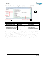
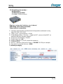
Fichier/Datei/file << bxxxx config.cfg >> ou/oder/or << bxxxx global.cfg >>
français
deutsch
english
1
1 = Signal extérieur
D’effacement de charge
1 = Externes Signal zum
Ladesstopp
1 = External signal fpr
Load shedding
2
0 = Effacement partiel
1 = Effacement Total
0 = partielle Ladereduktion
1 = totaler Ladestopp
0 = partial load readuction
1 = total erasure
3
À droite du signe # = zone de
commentaire et d’explication
Rechts eines # =
Kommentare und
Erklärungen
To the right of a # =
comments and explanations
Dans ce cas, toute charge commencée s’arrêtera dès que le signal extérieur 24Vdc
apparait et reprendra s’il disparait (attention : 3 effacements successifs maximum par
session de charge sont autorisés). /
Ladung wird bei aktivem externen 24V Signal gestoppt, und startet sobald Signal
nicht mehr anliegt /
Charge will stop while 24V signal is active and restart when signal is not present any
more
1
2
3

Witty
24 / 36
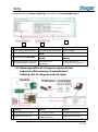
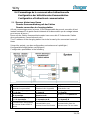
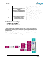
8.4 Paramétrage de la communication bidirectionnelle
8.4 Konfiguration der bidirektionalen Kommunikation
8.4 Configuration of bidirectional communication
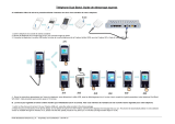
Serveur distant vers Borne 8.4.1
8.4.1 Remote Serververbindung mit der Station
8.4.1 Remote connection to charging station
Afin de communiquer avec la borne, il est indispensable de pouvoir connaitre à tout
instant l’adresse IP du point d’accès internet de la borne ainsi que le routage interne
pour trouver la borne /
Bevor mit der Station kommuniziert werden kann muss die IP Adresse der Station
dem verbundenen Server bekannt sein /
The IP address of the charging station has to be known by the connected server all
times
Suivant les projets, une des configurations suivantes sera à privilégier /
Konfigurationsmöglichkeiten nachfolgend /
Configuration possibilities in the following
français
Deutsch
english
1
ADSL – FAI IP fixe
(standard ou paramétré)
ADSL – FAI feste IP
(Standard oder eingestellt)
ADSL – FAI fixed IP
(Standard or set)
2
GPRS – SIM publique –
FAI IP fixe
GPRS – öffentliche SIM –
FAI feste IP
GPRS – public SIM –
FAI fixed IP
3
1. ADSL – FAI
IP dynamique
1. ADSL – FAI
dynamische IP
1. ADSL – FAI dynamic IP
2. GPRS – SIM publique –
FAI IP dynamique
2. GPRS – öffentliche SIM –
FAI dynamische IP
2. GPRS – public SIM –
FAI dynamic IP
5
Permettre une
communication descendante
du serveur distant VERS la
borne
Erlauben Sie Downlink-
Kommunikation vom
Remote-Server ZUR Station
Allow downlink
communication from the
remote server TO the station
Page is loading ...
Page is loading ...
Page is loading ...
Page is loading ...
Page is loading ...
Page is loading ...
Page is loading ...
Page is loading ...
Page is loading ...
Page is loading ...
Page is loading ...
Page is loading ...
-
 1
1
-
 2
2
-
 3
3
-
 4
4
-
 5
5
-
 6
6
-
 7
7
-
 8
8
-
 9
9
-
 10
10
-
 11
11
-
 12
12
-
 13
13
-
 14
14
-
 15
15
-
 16
16
-
 17
17
-
 18
18
-
 19
19
-
 20
20
-
 21
21
-
 22
22
-
 23
23
-
 24
24
-
 25
25
-
 26
26
-
 27
27
-
 28
28
-
 29
29
-
 30
30
-
 31
31
-
 32
32
-
 33
33
-
 34
34
-
 35
35
-
 36
36


Ask a question and I''ll find the answer in the document
Finding information in a document is now easier with AI
in other languages
- français: Hager Witty Guide d'installation
- Deutsch: Hager Witty Installationsanleitung
Related papers
Other documents
-
 EM2GO EMN022AS0GMB Owner's manual
-
 EM2GO EMN044ADS0GMB Owner's manual
-
Legrand 057012 User guide
-
 FREE GSM WIFI (PIRELLI) Owner's manual
-
VESTEL Charging station02-AC3 Series User manual
-
-
Hyundai HY3200SEI Owner's manual
-
 Circontrol Post eVolve Series Installation guide
-
Alpha Atrox Installation guide
-
Torqeedo Ultralight 403 A / 403 AC / 1103 AC Operating instructions


