EN
FR
Proper Use
This wenglor product has to be used according to the
following functional principle:
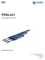
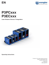
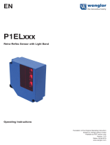
Reex Sensors with Background Suppression
Reflex sensors with background suppression analyze the light
reflected from objects. As these sensors work according to
the principle of angular measurement, the color, shape and
surface characteristics of the object have almost no influence
on the detection range. Even dark objects can be reliably
detected against a bright background. The output is switched
as soon as an object passes the selected range.
Safety Precautions
• This operating instruction is part of the product and must
be kept during its entire service life.
• Read this operating instruction carefully before using the
product.
• Installation, start-up and maintenance of this product has
only to be carried out by trained personnel.
• Tampering with or modifying the product is not permissible.
• Protect the product against contamination during start-up.
• Not a safety component in accordance with the EU Machin-
ery Directive.
Laser/LED Warning
Class Laser 2 (EN 60825-1)
Observe all applicable standards and safety precautions. The
enclosed laser warning labels must be attached and
visible at all time. Do not stare into beam.
LASER RADIATION -
DO NOT STARE INTO BEAM
620 - 690 nm < 1mW
CLASS 2 LASER PRODUCT
CAUTION
EN60825-1: 2014
Pp= 5 mW, t= 5 µs, λ= 620-690 nm
LASER
2
CAUTION!
Use of controls, adjustments or performance of
procedures other than those specified herein may
result in hazardous radiation exposure.
Notice d’utilisation
Ce produit wenglor doit être utilisé selon le mode de
fonctionnement suivant :
Capteurs réex à élimination d’arrière-plan
Les capteurs réflex à élimination d’arrière-plan exploitent la
lumière réfléchie par des objets. Étant donné qu’ils travaillent
par goniométrie, la couleur, la forme et les caractéristiques de
la surface de l’objet n’ont pratiquement aucune influence sur
la distance de travail. Même des objets foncés sont détectés
de manière fiable devant un fond clair. La sortie est commutée
quand un objet atteint la distance de travail réglée.
Consignes de sécurité
• Cette notice d’utilisation fait partie intégrante du produit et
doit être conservée durant toute la durée de vie du produit.
• Lisez la notice d’utilisation avant la mise sous tension.
• L’installation, les raccordements et les réglages doivent être
effectués uniquement par du personnel qualifié.
• Toute intervention ou modification sur le produit est proscrite.
• Lors de la mise en service, veillez à protéger l’appareil
d’éventuelles salissures.
• Aucun composant de sécurité selon la directive
« Machines » de l’Union Européenne.
Laser/LED Mise en garde
Appareil à laser de classe 2 (EN 60825-1)
Respecter les normes et prescriptions de sécurité. Observer
les instructions annexées. Ne pas regarder dans le faisceau.
LASER RADIATION -
DO NOT STARE INTO BEAM
620 - 690 nm < 1mW
CLASS 2 LASER PRODUCT
CAUTION
EN60825-1: 2014
Pp= 5 mW, t= 5 µs, λ= 620-690 nm
LASER
2
ATTENTION !
L’utilisation de procédure de réglages et de
mise en service autre que celle-ci peut vous expo-
ser à des radiations dangereuses.
Technical Data
Range 150 mm
Adjustable Range 35…150 mm
Switching Hysteresis < 5 %
Light Source Laser (red)
Wave Length 655 nm
Service Life (T = 25 °C) 100000 h
Laser Class (EN 60825-1) 2
max. Ambient Light 10000 Lux
Light Spot Diameter see Table 1
Supply Voltage 10…30 V DC
Current Consumption (Ub = 24 V) < 25 mA
Switching Frequency 1300 Hz
Response Time 385 µs
Temperature Drift < 5 %
Temperature Range −25…60 °C
Switching Output Voltage Drop < 2,5 V
Short Circuit Protection yes
Reverse Polarity Protection yes
Overload Protection yes
Housing Stainless Steel
Full Encapsulation yes
Degree of Protection IP67
Connection M12×1
Protection Class III
Light Spot Diameter
Range 50 mm 100 mm 150 mm
Light Spot Diameter 1,2 mm < 0,5 mm 1,5 mm
Table 1
YD24 YW24
Order No. PA3 NA3 PBV3 PA3
Connection Diagram No. 101 301 103 101
Control Panel D18* D18*
Suitable Mounting
Technology No. 150, 160 150
PNP NO
contamination output
PNP NC, NO antivalent
NPN NC, NO antivalent
NPN Switching Output/
Switching Current 100 mA
PNP Switching Output/
Switching Current 200 mA 200 mA 200 mA
M18×1 straight
M18×1 angled
* Valid for all sensors starting with revision F (YD24PA3, YD24NA3, YD24PBBV3) /
Revision E (YW24PA3). Revision can be found on production order number “xxxxx/F/
xxxxxx” shown on the product type label.
Données techniques
Distance de travail 150 mm
Plage ajustable 35…150 mm
Hystérésis de commutation < 5 %
Type de lumière Laser (rouge)
Longueur d’onde 655 nm
Durée de vie (Tu = 25 °C) 100000 h
Classe laser (EN 60825-1) 2
Ambiance lumineuse max. 10000 Lux
Diamètre du spot lumineux Voir tableau 1
Tension d’alimentation 10…30 V DC
Consommation (Ub = 24 V) < 25 mA
Fréquence de commutation 1300 Hz
Temps de réponse 385 µs
Dérive en température < 5 %
Température d’utilisation −25…60 °C
Chute de tension sortie de commutation < 2,5 V
Protection contre les courts-circuits oui
Protection contre les inversions de polarité oui
Protection contre les surcharges oui
Matière du boîtier Inox
Electronique noyée oui
Degré de protection IP67
Mode de raccordement M12×1
Catégorie de protection III
Diamètre du spot lumineux
Distance de détection 50 mm 100 mm 150 mm
Diamètre du spot lumineux 1,2 mm < 0,5 mm 1,5 mm
tableau 1
YD24 YW24
Référence PA3 NA3 PBV3 PA3
Schéma de
raccordement N° 101 301 103 101
Panneau
No. de Technique de
montage appropriée 150, 160 150
PNP Fermeture
Sortie d’encrassement
PNP Ouverture,
Fermeture antivalent
NPN Ouverture,
Fermeture antivalent
Courant commuté NPN sortie de
commutation 100 mA
Courant commuté PNO sortie
de commutation
200
mA
200
mA 200 mA
M18×1 Droit
M18×1 Coudé
* Valable pour tous les capteurs à partir de la révision F (YD24PA3, YD24NA3, YD-
24PBBV3) / Revision E (YW24PA3). La révision peut être déduite du numéro d’ordre
de production « xxxxx/F/xxxxxx » qui figure sur la plaque signalétique du produit.
Switching distance
All specified switching distances apply to white, matt Kodak
paper, 200 g/m2, with a surface area of 40 × 40 cm with light
striking at a 90° angle at room temperature (25 °C).
The Minimum Switching Distance is the Rated Switching
Distance × 0,9 (at room temperature 25 °C).
Complementary Products (see catalog)
wenglor offers Connection Technology for field wiring.
Suitable Mounting Technology No.
Suitable Connection Technology
No.
Dust extraction tube STAUBTUBUS-01
Mounting instructions
During operation of the Sensors, the corresponding electrical
and mechanical regulations, as well as safety regulations must
be observed. The Sensor must be protected from mechanical
impact.
Initial Operation
Attention!
Applied torque may not exceed 40 Nmm when turning the
potentiometer to its limit stops. The potentiometer would
otherwise be damaged.
Adjustment
Object recognition on a background or underlying surface
• Adjust the instrument and securely fix it, so that the beam
spot falls on the object to be detected.
• Remove the object and turn back the adjustment screw until
the apparatus switches off. The background and underlying
surface are now suppressed.
• Replace the object under the illuminated spot and check that
the Sensor switches on again.
Object recognition without disturbing background
• Adjust the instrument and securely fix it, so that the beam
spot falls on the object to be detected.
• Turn back the adjustment screw until the apparatus switches
off and then turn it forward to until it switches on. If neces-
sary turn it forward a bit further to increase the reliability of
the switching.
The focal distance is the distance from the Sensor to the point
at which the laser spot is smallest. It is about 100 mm for
YD24… and YW24… Sensors. Small objects and edges can
be recognized with great accuracy at focal distance.
In order to reliably detect objects with structured surfaces,
switching distance should not be set to focal distance.
Distance de détection
Toute les distances de travail sont testées en fonction
du papier blanc Kodak, Mat 200 g/m², d’une surface de
40 × 40 cm et faisceau lumineux perpendiculaire à la surface, à
température ambiante de 25 °C. La distance de commutation
minimale c’est la distance de commutation mesurée × 0,9
(température ambiante 25 °C).
Produits complémentaires (voir catalogue)
wenglor vous propose la connectique adaptée à votre produit.
No. de Technique de montage
appropriée
Référence connectique appropriée
Embout anti-encrassement STAUBTUBUS-01
Instructions de montage
Lors de la mise en service des détecteurs respecter les
prescriptions de sécurité, normes et instructions électriques et
mécaniques appropriées. Protéger le détecteur contre toute
influence mécanique pouvant le dérégler ou endommager.
Mise en service
Attention!
Lorsque le potentiomètre est réglé en butée, veillez à ne pas
dépasser le couple de rotation maxi de 40 Nmm afin d’éviter
une destruction irréversible du potentiomètre.
Réglages
Détection d’un objet placé directement devant l’arrière-
plan et / ou le fond gênant
• Régler et monter le détecteur de manière à ce que le fais-
ceau lumineux tombe sur l’objet à détecter.
• Enlever l’objet et tourner le potentiomètre lentement à
gauche jusqu’ à ce que le détecteur soit coupé. L’arrière-
plan et / ou le fond perturbateur sont ainsi éliminés.
• Replacer l’objet sous le spot lumineux et vérifier la remise en
marche du détecteur.
Détection d’un objet sans arrière-plan gênant
• Régler et monter le détecteur de manière à ce que le
faisceau lumineux tombe sur l’objet à détecter.
• Tourner le potentiomètre à gauche jusqu’à ce que le
détecteur soit coupé, puis tourner le vis de réglage à droite
jusqu’à la remise en marche du détecteur. Si besoin est,
continuer à tourner le potentiomètre afin d’assurer une
bonne commutation.
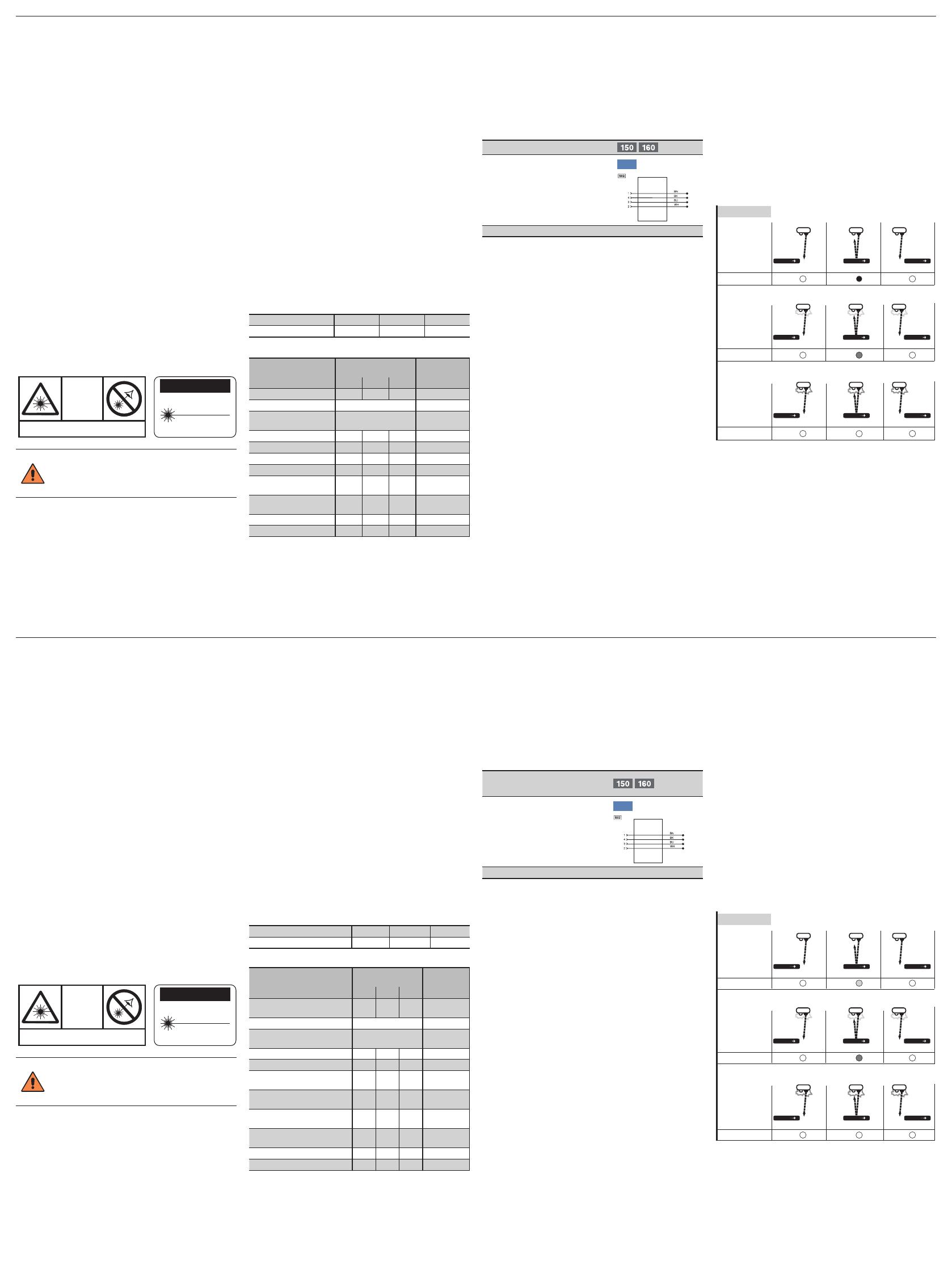
Contamination Warning (blinking LED):
• Sensor(lens) is contaminated
• Distance Sensor – object too big
• Incorrect mounted
• Transmitting diode aged
• Uncertain working range
• Short circuit
This sensors are run for a short time in the unstable
range of operation with every change from the unswitched to
the switched condition. The contamination warning is only ac-
tivated, when this unstable range of operation persists longer
than 200 ms (see fig. 1).
Diagram Contamination Output/Contamination Warning
not detected not detecteddetected
beginning contamination
Object Object Object
not detected not detecteddetected
Reflex Mode no contamination
Object Object Object
Object
Switching Status
Indicator
Object
Switching Status
Indicator
Object
Switching Status
Indicator
not detected not detectednot detected
advanced contamination
Object Object Object
off offon
off off
off off
blinking
off
Fig. 1
Proper Disposal
wenglor Sensoric GmbH does not accept the return of
unusable or irreparable products. Respectively valid national
waste disposal regulations apply to product disposal.
La distance de focalisation est la distance entre le détecteur
et l’endroit, où le spot laser est le plus petit. Pour les détecteur
YD24 / YW24, elle se situe environ à 100 mm.
A cette distance de focalisation de très petits objets peuvent
être détectés, tels que des arêtes avec une grande précision.
Pour détecter un objet avec une surface texturée de façon
sure, la distance de commutation ne doit pas être supérieure à
la distance de focalisation.
Déclenchement du signal d’encrassement (LED clignote) :
• Encrassement du détecteur
• Distance détecteur-objet trop grande
• Erreur de montage
• Vieillissement des diodes émettrices
• Zone de détection incertaine
• Court-Circuit
La sortie d’encrassement de ces détecteurs est activée après
une temporisation de 200 ms. Ceci en raison de la zone de
détection incertaine lors d’un changement de signal de
commutation (voir Fig. 1).
Diagramme Sortie et signalisation d’encrassement
non detécté non detéctédetécté
début d’encrassement
Objet Objet Objet
non detécté non detéctédetécté
Mode réflex pas d’encrassement
Objet Objet Objet
Objet
Signalisation de
commutation
Objet
Signalisation de
commutation
Objet
Signalisation de
commutation
non detécté non detécténon detécté
encrassement avancé
Objet Objet
éteint éteintallumée
éteint éteint
éteint éteint
clignote
éteint
Objet
Fig. 1
Mise au rebut
La société wenglor sensoric GmbH ne reprend ni les produits
inutilisables ni les produits irréparables. Veuillez respecter la
réglementation en vigueur en mettant le produit au rebut dans
un endroit prévu à cet effet par les autorités publiques.