Page is loading ...

INSTRUCTION MANUAL
HELPLINE CALL FCSI LTD ON 01789 207419

DESCRIPTION TORQUE
1 A-Head Steerer Clamp Bolts 20Nm
(where fitted)
2 Stem Binder Bolt 15Nm
3 Brake Fixing Bolt (non disc) 5Nm
Applies to both front and rear brake
4 Axle Nut 30Nm
QR Axle 5Nm
5 Chain Wheel Securing Bolt 38Nm
6 Pedal 40Nm
7 F/Derailleur Cable Fixing Bolt 4Nm
8 R/Derailleur Cable Fixing Bolt 4Nm
9 Seat Pin (Allen Head) 20-35Nm
10 Saddle Clamp Bolt 30Nm
11 F/Derailleur Clamp Bolt 5.5Nm
TABLE OF RECOMMENDED TORQUE VALUES
Page 1
1
2
3
4
5
6
7
8
9
10
11
Warranty
Roux bikes are guaranteed against material defects or faults of manufacturing from
the date of the original purchase as follows.
Frame & forks.
Roux frames and forks are warranted against failure or defects for a period of fol-
lowing years.
1 year on double suspension frames.
1 year on suspension forks.
Lifetime on alloy frame & forks.
5 years on rigid carbon frame & forks.
Component Parts
Component parts are warranted against failure or defects for a period of up to one
year.
Note:
1. This warranty applies only to the original owner and is not transferable.
2. Claims under this warranty must be made through the original place of
purchase or an authorised dealer. Proof of purchase is required.
3. This warranty does not apply to damage or failure due to accidents, misuse,
abuse or neglect. Modification of the frame or components shall void this
warranty.
4. This warranty does not cover normal wear and tear, improper assembly by a
third party or poor maintenance or installation of parts or accessories not
originally intended or compatible with the cycle.
This bicycle has been designed to meet or exceed the requirements relevant to its
intended use and categorization within the CEN standard. As part of
this process this
bicycle has been assigned to one of the specific categories.
misuse, modification, or misunderstanding the intended purpose of the bicycle
could result in component failure and potentially serious injury. For your safety and
your warranty vaildation you must use your bicycle correctly and as intended by the
manufacturer.
If you are in any doubt as to the intended use of your cycle you must clarify it with your
retailer before riding.
We recommend a total rider + bike + luggage weight that does not exceed 120Kg.
Although exceeding this may not necessarily be unsafe we do advise you to check your
intended use with your retailer for clarification.
This warranty does not affect the statutory rights of the consumer, in itself this
warranty does not cover incidental or consequential damage.
We recommend you record your cycle serial number stamped on the frame but a far
Page 2
Page 1
Page 2
DESCRIPTION TORQUE
1 A-Head Steerer Clamp Bolts 20Nm
(where fitted)
2 Stem Binder Bolt 15Nm
3 Brake Fixing Bolt (non disc) 5Nm
Applies to both front and rear brake
4 Axle Nut 30Nm
QR Axle 5Nm
5 Chain Wheel Securing Bolt 38Nm
6 Pedal 40Nm
7 F/Derailleur Cable Fixing Bolt 4Nm
8 R/Derailleur Cable Fixing Bolt 4Nm
9 Seat Pin (Allen Head) 20-35Nm
10 Saddle Clamp Bolt 30Nm
11 F/Derailleur Clamp Bolt 5.5Nm
TABLE OF RECOMMENDED TORQUE VALUES
Page 1
1
2
3
4
5
6
7
8
9
10
11
1
2
3
4
5
6
78
9
10
11

DESCRIPTION TORQUE
1 A-Head Steerer Clamp Bolts 20Nm
(where fitted)
2 Stem Binder Bolt 15Nm
3 Brake Fixing Bolt (non disc) 5Nm
Applies to both front and rear brake
4 Axle Nut 30Nm
QR Axle 5Nm
5 Chain Wheel Securing Bolt 38Nm
6 Pedal 40Nm
7 F/Derailleur Cable Fixing Bolt 4Nm
8 R/Derailleur Cable Fixing Bolt 4Nm
9 Seat Pin (Allen Head) 20-35Nm
10 Saddle Clamp Bolt 30Nm
11 F/Derailleur Clamp Bolt 5.5Nm
TABLE OF RECOMMENDED TORQUE VALUES
Page 1
1
2
3
4
5
6
7
8
9
10
11
Warranty
Roux bikes are guaranteed against material defects or faults of manufacturing from
the date of the original purchase as follows.
Frame & forks.
Roux frames and forks are warranted against failure or defects for a period of fol-
lowing years.
1 year on double suspension frames.
1 year on suspension forks.
Lifetime on alloy frame & forks.
5 years on rigid carbon frame & forks.
Component Parts
Component parts are warranted against failure or defects for a period of up to one
year.
Note:
1. This warranty applies only to the original owner and is not transferable.
2. Claims under this warranty must be made through the original place of
purchase or an authorised dealer. Proof of purchase is required.
3. This warranty does not apply to damage or failure due to accidents, misuse,
abuse or neglect. Modification of the frame or components shall void this
warranty.
4. This warranty does not cover normal wear and tear, improper assembly by a
third party or poor maintenance or installation of parts or accessories not
originally intended or compatible with the cycle.
This bicycle has been designed to meet or exceed the requirements relevant to its
intended use and categorization within the CEN standard. As part of
this process this
bicycle has been assigned to one of the specific categories.
misuse, modification, or misunderstanding the intended purpose of the bicycle
could result in component failure and potentially serious injury. For your safety and
your warranty vaildation you must use your bicycle correctly and as intended by the
manufacturer.
If you are in any doubt as to the intended use of your cycle you must clarify it with your
retailer before riding.
We recommend a total rider + bike + luggage weight that does not exceed 120Kg.
Although exceeding this may not necessarily be unsafe we do advise you to check your
intended use with your retailer for clarification.
This warranty does not affect the statutory rights of the consumer, in itself this
warranty does not cover incidental or consequential damage.
We recommend you record your cycle serial number stamped on the frame but a far
Page 2
Page 1
Page 2
Warranty
COLORADO
COLORADO
bikes are guaranteed against material defects or faults of
manufacturing
from
the date of the original purchase as follows.
Frame
& forks.
frames and forks are warranted against failure or defects for a
period
of
fol
lowing years.
1 year on double suspension frames.
1 year on suspension forks.
Lifetime on alloy frame & forks.
5 years on rigid carbon frame & forks.
C
omponent Parts
Component parts are warranted against failure or defects for a period of up to one
year.
No
te:
1. This warranty applies only to the original owner and is not transferable.
2. Claims under this warranty must be made through the original place of
purchase or an authorised dealer. Proof of purchase is required.
3. This warranty does not apply to damage or failure due to accidents, misuse,
abuse or neglect. Modification of the frame or components shall void this
warranty.
4. This warranty does not cover normal wear and tear, improper assembly by a
third party or poor maintenance or installation of parts or accessories not
originally intended or compatible with the cycle.
This bicycle has been designed to meet or exceed the requirements relevant to its
intended use and categorization within the ISO4210 standard. As part of this process
this
bicycle has been assigned to one of the specific categories.
misuse, modification, or misunderstanding the intended purpose of the bicycle
could result in component failure and potentially serious injury. For your safety and
your warranty vaildation you must use your bicycle correctly and as intended by the
manufacturer.
If you are in any doubt as to the intended use of your cycle you must clarify it with your
retailer before riding.
We recommend a total rider + bike + luggage weight that does not exceed 120Kg.
Although exceeding this may not necessarily be unsafe we do advise you to check your
intended use with your retailer for clarification.
This warranty does not affect the statutory rights of the consumer, in itself this
warranty does not cover incidental or consequential damage.
We recommend you record your cycle serial number stamped on the frame but a far
Page 2

Page 3
PARTS DESCRIPTION
ROUTINE MAINTENANCE CHECKS AND LUBRICATION OF TYPICAL BICYCLE
Seat and Stem Nuts
Be sure seat and
stem nuts are tight.
Disc Brake
(Routine maintenance by your
dealer recommended).
Gears
Front - Rear - Lightly
oil moving parts. Maintain
adjustments of front and
rear derailleurs.
Half Yearly
Remove and clean, lubricate
chain, derailleur gears and all
cables. Check and replace as
required.
Bottom Bracket
Clean, regrease yearly
checking for wear.
Wheels
Check that axles are sealed
and secured properly. Rims
should be kept free from
wax, oil, grease and glue.
Check for loose or missing
spokes.
Chain
Keep lightly oiled, clean and lubricate regu
-
larly or as condition dictates (at least every
4th ride).
Cranks
Grease bearings monthly.
Check that axle bolts or
cotterpin bolts are tight.
Check for free play in
bottom bracket.
Yearly, remove, clean and
regrease hub axles, bottom
bracket set and headset.
Reflectors (pedal)
Check all fittings are secure.
Pedals
Lightly oil bearings
monthly.
Wheel Hubs
Grease bearings monthly.
Adjust cones to avoid free
play from side to side.
Disc Brakes
(Routine maintenance by your
dealer recommended.)
Reflectors
Check monthly.
Securely fixed.
Tyres
Check for cuts and wear.
Maintain pressure indicated
on tyre wall for maximum
efficiency.
Front Suspension unit
(Dealer adjustment only)
Reflectors (front & rear)
Ensure reflectors are secure and
undamaged. Replace if necessary.
Brakes
Lightly oil exposed cables monthly.
Maintain adjustment and replace
brake blocks when worn, brake cables
when frayed.
Handlebars
Check handlebar bolt is tight. Check
brake levers securely mounted to
bars and brakes stop smoothly and
efficiently.
Stem Nuts
Ensure stem nuts
and bolts are tight.
Headset
Remove, clean and
regrease bearings
yearly, checking
if replacements
required.
NB
Wash cycle weekly with warm soapy water and polish dry with
a soft cloth
Frame
Number.
Page 4
NB
Wash cycle weekly with warm soapy water and polish dry with
a soft cloth
YOUR BICYCLE — OWNER’S RESPONSIBILITY
Owner’s Responsibility and Important Points
Point 1 Carefully and thoroughly read this manual and follow the
instructions.
Point 2 Any major service or adjustments on your bicycle should be carried
out by a professional repairer; however if this service is not available
and you wish to make adjustments yourself, this manual contains
important tips on how to do it.
Point 3 CAUTION: Any adjustments you make are entirely your own risk.
Caution: To use your bicycle for freestyle and stunt riding,
competitive events, off-road use or any similar activities can be
dangerous and you are warned that you assume the risk for personal
injury, damages or losses incurred from such use. The Retailer shall
not be liable to the purchaser of the bicycle or to third parties for
consequential or special damages.
Point 4 Bicycles are built with a variety of equipment and accessories, and
you should familiarise yourself with their function and purpose, to
make sure you can operate them correctly.
This manual is not intended as a comprehensive service or maintenance manual, see your
dealer for all service, repair or maintenance queries.
SAFE CYCLING AND SAFETY TIPS
Before you ride your bicycle at any time make sure it is in a safe operating condition.
Particularly check that your:-
• Bicycle’s nuts, bolts and parts are tight and not worn or damaged.
• Riding position is comfortable.
• Brakes are operating effectively.
• Steering is free with no excessive play.
• Wheels run true and hub bearings are correctly adjusted.
• Wheels are properly secured and locked to frame/fork.
• Tyres are in good condition and inflated to correct pressure.
• Pedals are securely tightened to pedal cranks.
• Gears are correctly adjusted.
• All reflectors are in position.
• Before riding please note that the right hand brake lever operates the
front brake (in the U.K), and the left lever operates the rear brake (in the
U.K).
After you have made any adjustments to your bicycle, check that all nuts, bolts are
securely tightened and cables are free from kinks and fixed securely to the bicycle
frame.
Page 3
Page 4
if fitted
if fitted

Page 3
PARTS DESCRIPTION
ROUTINE MAINTENANCE CHECKS AND LUBRICATION OF TYPICAL BICYCLE
Seat and Stem Nuts
Be sure seat and
stem nuts are tight.
Disc Brake
(Routine maintenance by your
dealer recommended).
Gears
Front - Rear - Lightly
oil moving parts. Maintain
adjustments of front and
rear derailleurs.
Half Yearly
Remove and clean, lubricate
chain, derailleur gears and all
cables. Check and replace as
required.
Bottom Bracket
Clean, regrease yearly
checking for wear.
Wheels
Check that axles are sealed
and secured properly. Rims
should be kept free from
wax, oil, grease and glue.
Check for loose or missing
spokes.
Chain
Keep lightly oiled, clean and lubricate regu
-
larly or as condition dictates (at least every
4th ride).
Cranks
Grease bearings monthly.
Check that axle bolts or
cotterpin bolts are tight.
Check for free play in
bottom bracket.
Yearly, remove, clean and
regrease hub axles, bottom
bracket set and headset.
Reflectors (pedal)
Check all fittings are secure.
Pedals
Lightly oil bearings
monthly.
Wheel Hubs
Grease bearings monthly.
Adjust cones to avoid free
play from side to side.
Disc Brakes
(Routine maintenance by your
dealer recommended.)
Reflectors
Check monthly.
Securely fixed.
Tyres
Check for cuts and wear.
Maintain pressure indicated
on tyre wall for maximum
efficiency.
Front Suspension unit
(Dealer adjustment only)
Reflectors (front & rear)
Ensure reflectors are secure and
undamaged. Replace if necessary.
Brakes
Lightly oil exposed cables monthly.
Maintain adjustment and replace
brake blocks when worn, brake cables
when frayed.
Handlebars
Check handlebar bolt is tight. Check
brake levers securely mounted to
bars and brakes stop smoothly and
efficiently.
Stem Nuts
Ensure stem nuts
and bolts are tight.
Headset
Remove, clean and
regrease bearings
yearly, checking
if replacements
required.
NB
Wash cycle weekly with warm soapy water and polish dry with
a soft cloth
Frame
Number.
Page 4
NB
Wash cycle weekly with warm soapy water and polish dry with
a soft cloth
YOUR BICYCLE — OWNER’S RESPONSIBILITY
Owner’s Responsibility and Important Points
Point 1 Carefully and thoroughly read this manual and follow the
instructions.
Point 2 Any major service or adjustments on your bicycle should be carried
out by a professional repairer; however if this service is not available
and you wish to make adjustments yourself, this manual contains
important tips on how to do it.
Point 3 CAUTION: Any adjustments you make are entirely your own risk.
Caution: To use your bicycle for freestyle and stunt riding,
competitive events, off-road use or any similar activities can be
dangerous and you are warned that you assume the risk for personal
injury, damages or losses incurred from such use. The Retailer shall
not be liable to the purchaser of the bicycle or to third parties for
consequential or special damages.
Point 4 Bicycles are built with a variety of equipment and accessories, and
you should familiarise yourself with their function and purpose, to
make sure you can operate them correctly.
This manual is not intended as a comprehensive service or maintenance manual, see your
dealer for all service, repair or maintenance queries.
SAFE CYCLING AND SAFETY TIPS
Before you ride your bicycle at any time make sure it is in a safe operating condition.
Particularly check that your:-
• Bicycle’s nuts, bolts and parts are tight and not worn or damaged.
• Riding position is comfortable.
• Brakes are operating effectively.
• Steering is free with no excessive play.
• Wheels run true and hub bearings are correctly adjusted.
• Wheels are properly secured and locked to frame/fork.
• Tyres are in good condition and inflated to correct pressure.
• Pedals are securely tightened to pedal cranks.
• Gears are correctly adjusted.
• All reflectors are in position.
• Before riding please note that the right hand brake lever operates the
front brake (in the U.K), and the left lever operates the rear brake (in the
U.K).
After you have made any adjustments to your bicycle, check that all nuts, bolts are
securely tightened and cables are free from kinks and fixed securely to the bicycle
frame.
Page 3
Page 4
Page 4
NB
Wash cycle weekly with warm soapy water and polish dry with
a soft cloth
YOUR BICYCLE — OWNER’S RESPONSIBILITY
Owner’s Responsibility and Important Points
Point 1 Carefully and thoroughly read this manual and follow the
instructions.
Point 2 Any major service or adjustments on your bicycle should be carried
out by a professional repairer; however if this service is not available
and you wish to make adjustments yourself, this manual contains
important tips on how to do it.
Point 3 CAUTION: Any adjustments you make are entirely your own risk.
Caution: To use your bicycle for freestyle and stunt riding,
competitive events, off-road use or any similar activities can be
dangerous and you are warned that you assume the risk for personal
injury, damages or losses incurred from such use. The Retailer shall
not be liable to the purchaser of the bicycle or to third parties for
consequential or special damages.
Point 4 Bicycles are built with a variety of equipment and accessories, and
you should familiarise yourself with their function and purpose, to
make sure you can operate them correctly.
This manual is not intended as a comprehensive service or maintenance manual, see your
dealer for all service, repair or maintenance queries.
SAFE CYCLING AND SAFETY TIPS
Before you ride your bicycle at any time make sure it is in a safe operating condition.
Particularly check that your:-
• Bicycle’s nuts, bolts and parts are tight and not worn or damaged.
• Riding position is comfortable.
• Brakes are operating effectively.
• Steering is free with no excessive play.
• Wheels run true and hub bearings are correctly adjusted.
• Wheels are properly secured and locked to frame/fork.
• Tyres are in good condition and inflated to correct pressure.
• Pedals are securely tightened to pedal cranks.
• Gears are correctly adjusted.
• All reflectors are in position.
• Before riding please note that the right hand brake lever operates the
front brake (in the U.K), and the left lever operates the rear brake (in the
U.K).
After you have made any adjustments to your bicycle, check that all nuts, bolts are
securely tightened and cables are free from kinks and fixed securely to the bicycle
frame.

Every six months (more frequently if high mileage or subject to heavy use) your bicycle
should be professionally checked to ensure that it is in correct and safe working order.
But remember, it is the responsibility of the rider to ensure all parts are in working
order, prior to riding the bike.
When Riding:
• Be aware of and obey current traffic regulations.
• Always obey all traffic regulations.
• Know and observe all local laws and rules for bicycles.
• Give clear hand signals in good time to warn other road users of
your intentions.
• Be aware of vehicles pulling in or out of traffic and for doors
being opened on parked cars.
• Always keep both your hands on the handlebars and your feet on
the pedals and also sit correctly on the seat at all times.
• Wear a protective cycling helmet and make sure no loose clothes can
catch in your wheels or chain.
• Take care to ride at a speed to suit the conditions and extra care
should be taken when riding on uneven surfaces, loose sand or gravel. Be alert
and avoid potholes, drain covers and grates or other road hazards.
Do Nots
• Do not ride on same side of road as oncoming traffic.
• Do not ride two abreast.
• Do not carry a passenger unless cycle is equipped to do so.
• Do not swerve in and out of traffic.
• Do not hang items over the handlebars to impede steering or catch in
the front wheel.
• Do not hold on to another vehicle.
• Do not ride too close behind another vehicle.
Caution: Wet Weather Riding
No brakes work as well under wet or icy conditions as they do under dry conditions.
In wet weather special precautions must be taken to assure safe stopping. Ride slower
than normal and apply your brakes well in advance of anticipated stops.
Caution: Night Riding
If you intend to ride on public roads, especially in the dark hours you should ensure
that your cycle is equipped with any legally required parts such as reflectors and
lights.
Check that the reflectors are firmly secured in their correct position and clean and not
obscured. Damaged reflectors must be replaced immediately.
5
Page 5
Page 6
General Suspension Units Notes
Your cycle may be fitted with suspension units built into parts of the frame and forks
We recommend these are serviced by your dealer as required. More information may be
found in the suspension manufacturers details supplied with your cycle.
Riding Position
It is important that you and your bicycle are fitted to each other, not only for
comfort and riding ease but for control and safety. Normally your Dealer will custom
fit your bicycle to you but the following few pages should help you to find your most
comfortable, safe and efficient position.
SEAT
Seat Adjustment
Loosen the nut on the seat-post clamp enough to allow the saddle to move forward and
back. The seat can then be aligned forward and back and the angle can also be adjusted
(it is recommended that the seat be parallel to the ground).
To adjust the seat up and down, loosen the binder-bolt on the seat tube, position the seat
and re-tighten the binder-bolt.
To adjust the saddle height for comfortable, safe riding you should release the seat pin
clamp mechanism with the tool provided and slide the seat post up and down to a position
whereby the riders leg is not quite fully extended at the lowest point of the pedal stroke.
This will give you the most efficient pedalling action. You may wish to tailor this to allow for,
the use of various footwear, personal mobility, and the ease of mounting and dismounting.
Retighten the seat pillar clamp mechanism so that the saddle is securely held in position
before riding.
CAUTION
The seat pillar has a minimum insertion mark and
this should not be visible. Always ensure this mark is
within the frame. Component and /or frame failure
can occur if the seat post is not inserted far enough
and serious injury could result.
If in doubt contact your retailer.
Warning: Bicycle should not be ridden if seat
adjustments are not properly tightened.
Saddle
Seat Post
Minimum
Insertion mark
Page 5
Page 6
Every six months (more frequently if high mileage or subject to heavy use) your bicycle
should be professionally checked to ensure that it is in correct and safe working order.
But remember, it is the responsibility of the rider to ensure all parts are in working
order, prior to riding the bike.
When Riding:
• Be aware of and obey current traffic regulations.
• Always obey all traffic regulations.
• Know and observe all local laws and rules for bicycles.
• Give clear hand signals in good time to warn other road users of
your intentions.
• Be aware of vehicles pulling in or out of traffic and for doors
being opened on parked cars.
• Always keep both your hands on the handlebars and your feet on
the pedals and also sit correctly on the seat at all times.
• Wear a protective cycling helmet and make sure no loose clothes can
catch in your wheels or chain.
• Take care to ride at a speed to suit the conditions and extra care
should be taken when riding on uneven surfaces, loose sand or gravel. Be alert
and avoid potholes, drain covers and grates or other road hazards.
Do Nots
• Do not ride on same side of road as oncoming traffic.
• Do not ride two abreast.
• Do not carry a passenger unless cycle is equipped to do so.
• Do not swerve in and out of traffic.
• Do not hang items over the handlebars to impede steering or catch in
the front wheel.
• Do not hold on to another vehicle.
• Do not ride too close behind another vehicle.
Caution: Wet Weather Riding
No brakes work as well under wet or icy conditions as they do under dry conditions.
In wet weather special precautions must be taken to assure safe stopping. Ride slower
than normal and apply your brakes well in advance of anticipated stops.
Caution: Night Riding
If you intend to ride on public roads, especially in the dark hours you should ensure
that your cycle is equipped with any legally required parts such as reflectors and
lights.
Check that the reflectors are firmly secured in their correct position and clean and not
obscured. Damaged reflectors must be replaced immediately.
5
Page 5
Page 6
General Suspension Units Notes
Your cycle may be fitted with suspension units built into parts of the frame and forks
We recommend these are serviced by your dealer as required. More information may be
found in the suspension manufacturers details supplied with your cycle.
Riding Position
It is important that you and your bicycle are fitted to each other, not only for
comfort and riding ease but for control and safety. Normally your Dealer will custom
fit your bicycle to you but the following few pages should help you to find your most
comfortable, safe and efficient position.
SEAT
Seat Adjustment
Loosen the nut on the seat-post clamp enough to allow the saddle to move forward and
back. The seat can then be aligned forward and back and the angle can also be adjusted
(it is recommended that the seat be parallel to the ground).
To adjust the seat up and down, loosen the binder-bolt on the seat tube, position the seat
and re-tighten the binder-bolt.
To adjust the saddle height for comfortable, safe riding you should release the seat pin
clamp mechanism with the tool provided and slide the seat post up and down to a position
whereby the riders leg is not quite fully extended at the lowest point of the pedal stroke.
This will give you the most efficient pedalling action. You may wish to tailor this to allow for,
the use of various footwear, personal mobility, and the ease of mounting and dismounting.
Retighten the seat pillar clamp mechanism so that the saddle is securely held in position
before riding.
CAUTION
The seat pillar has a minimum insertion mark and
this should not be visible. Always ensure this mark is
within the frame. Component and /or frame failure
can occur if the seat post is not inserted far enough
and serious injury could result.
If in doubt contact your retailer.
Warning: Bicycle should not be ridden if seat
adjustments are not properly tightened.
Saddle
Seat Post
Minimum
Insertion mark
Page 5
Page 6
Page 6
General Suspension Units Notes
Your cycle may be fitted with suspension units built into parts of the frame and forks
We recommend these are serviced by your dealer as required. More information may be
found in the suspension manufacturers details supplied with your cycle.
Riding Position
It is important that you and your bicycle are fitted to each other, not only for
comfort and riding ease but for control and safety. Normally your Dealer will custom
fit your bicycle to you but the following few pages should help you to find your most
comfortable, safe and efficient position.
SEAT
Seat Adjustment
Loosen the nut on the seat-post clamp enough to allow the saddle to move forward and
back. The seat can then be aligned forward and back and the angle can also be adjusted
(it is recommended that the seat be parallel to the ground).
To adjust the seat up and down, loosen the binder-bolt on the seat tube, position the seat
and re-tighten the binder-bolt.
To adjust the saddle height for comfortable, safe riding you should release the seat pin
clamp mechanism with the tool provided and slide the seat post up and down to a position
whereby the riders leg is not quite fully extended at the lowest point of the pedal stroke.
This will give you the most efficient pedalling action. You may wish to tailor this to allow for,
the use of various footwear, personal mobility, and the ease of mounting and dismounting.
Retighten the seat pillar clamp mechanism so that the saddle is securely held in position
before riding.
CAUTION
The seat pillar has a minimum insertion mark and
this should not be visible. Always ensure this mark is
within the frame. Component and /or frame failure
can occur if the seat post is not inserted far enough
and serious injury could result.
If in doubt contact your retailer.
Warning: Bicycle should not be ridden if seat
adjustments are not properly tightened.
Saddle
Seat Post
Minimum
Insertion mark

Page 7
HANDLEBARS AND STEMS
As your cycle may be fitted with a standard ‘quill’ stem or an A-Head stem, you must always
check that all the bolts are tight before cycling.
Standard Stem: Loosen expander bolt so that expander wedge is not tight in bottom of
handlebar stem. Gently tap the top of the expander bolt to further loosen the wedge if
necessary. When the expander wedge is loose, move the handlebars up or down until you
find the optimum height at which you can easily reach the brake levers and comfortably
grasp the handlebars. Usually this height is level with, or slightly lower than, the top of the
saddle. Be sure the stem is in line with the front wheel.
When desirable height has been achieved, align the handlebar with the front wheel and
securely tighten expander bolt.
Caution: It is extremely important to tighten the expander bolt sufficiently, so that when
the wheel is held between your legs and the handlebars are twisted, the handlebars do not
move. Do not over tighten, as it may increase risk of injury to the rider. Position grip portion
of handlebars horizontally and securely tighten the binder bolt.
Note: Whenever the handlebar stem is removed from the head tube then the expander bolt
should be lightly greased.
A-Head stem: The height of the extension on A-head systems can be altered in 2 ways
either by disassembly of the bars and flipping the extension over. This gives a simple up or
down position of the extension angle or move the position of the extension spacers.
1. Remove compression cap and bolt.
2. Loosen clamp bolts that secure the extension to the steerer.
3. Remove the extension from steerer fit extra spacer washers or remove
them under the extension. This adjustment is limited as the compression bolt
must be able to engage the thread inside the steerer. Also the clamp bolts
must act onto the steerer directly.
4. If lowering the extension put the spacers you remove back on top of the
extension and under the compression cap. this saves re cutting the steerer.
5. Re tighten the compression cap to take slack up from the headset bearings.
6. Re tighten the steerer clamp bolts to lock everything in position.
Caution: Do not over tighten the top compression bolt, this should be pre-set to eliminate
bearing play, overtightening will cause premature wear.
If in doubt contact your retailer for service.
Page 8
6mm Allen Key
Handlebar
Stem Bolt
(Allen Head)
Recessed Type
A-Head Type
Compression Bolt
Steerer
Clamp Bolts
Compression Cap
5 Star Washer
Stem Bolts
Extension
Spacers
Bearing Seat
Top cup with Bearings
inside
Minimum Insertion
Mark
Binder Bolt
Stem Expander
Bolt
Standard Stem
BRAKES
WARNING
For safe riding it is important to completely understand the operation of your bicycle’s
brake system. Improper use of your bicycle’s brake system may result in a loss of
control or an accident, which could lead to severe injury. Because each bicycle may
handle differently, be sure to learn the proper braking technique (including brake lever
pressure and bicycle control characteristics) and operation of your bicycle. This can
be done by consulting your professional bicycle dealer and this owner’s manual, and by
practicing your riding and braking technique.
There are two brake mechanisms working independently. One on the front wheel and
the other on the rear wheel. The brakes are operated by hand levers fastened to the
handlebars. The right lever controls the front brake and the left lever controls the rear
brake.
To stop with safety:
1. Operate the rear brake (left lever) slightly before the front brake (right lever).
2. Apply firm pressure to both front and rear brake levers.
Caution: If the front brake is applied with too much pressure, the rider may
be thrown off the bicycle.
3. Never apply the front brake on a turn. This is especially dangerous when
cornering or riding on slippery or loose surface roads.
4. Brakes are less effective in wet weather. Ride slower and allow more distance
for stopping.
5. Do not ride your bicycle if the braking system is not working correctly. If you are
in doubt, take your bicycle to your dealer.
Page 7
Page 8
Page 7
HANDLEBARS AND STEMS
As your cycle may be fitted with a standard ‘quill’ stem or an A-Head stem, you must always
check that all the bolts are tight before cycling.
Standard Stem: Loosen expander bolt so that expander wedge is not tight in bottom of
handlebar stem. Gently tap the top of the expander bolt to further loosen the wedge if
necessary. When the expander wedge is loose, move the handlebars up or down until you
find the optimum height at which you can easily reach the brake levers and comfortably
grasp the handlebars. Usually this height is level with, or slightly lower than, the top of the
saddle. Be sure the stem is in line with the front wheel.
When desirable height has been achieved, align the handlebar with the front wheel and
securely tighten expander bolt.
Caution: It is extremely important to tighten the expander bolt sufficiently, so that when
the wheel is held between your legs and the handlebars are twisted, the handlebars do not
move. Do not over tighten, as it may increase risk of injury to the rider. Position grip portion
of handlebars horizontally and securely tighten the binder bolt.
Note: Whenever the handlebar stem is removed from the head tube then the expander bolt
should be lightly greased.
A-Head stem: The height of the extension on A-head systems can be altered in 2 ways
either by disassembly of the bars and flipping the extension over. This gives a simple up or
down position of the extension angle or move the position of the extension spacers.
1. Remove compression cap and bolt.
2. Loosen clamp bolts that secure the extension to the steerer.
3. Remove the extension from steerer fit extra spacer washers or remove
them under the extension. This adjustment is limited as the compression bolt
must be able to engage the thread inside the steerer. Also the clamp bolts
must act onto the steerer directly.
4. If lowering the extension put the spacers you remove back on top of the
extension and under the compression cap. this saves re cutting the steerer.
5. Re tighten the compression cap to take slack up from the headset bearings.
6. Re tighten the steerer clamp bolts to lock everything in position.
Caution: Do not over tighten the top compression bolt, this should be pre-set to eliminate
bearing play, overtightening will cause premature wear.
If in doubt contact your retailer for service.
Page 8
6mm Allen Key
Handlebar
Stem Bolt
(Allen Head)
Recessed Type
A-Head Type
Compression Bolt
Steerer
Clamp Bolts
Compression Cap
5 Star Washer
Stem Bolts
Extension
Spacers
Bearing Seat
Top cup with Bearings
inside
Minimum Insertion
Mark
Binder Bolt
Stem Expander
Bolt
Standard Stem
BRAKES
WARNING
For safe riding it is important to completely understand the operation of your bicycle’s
brake system. Improper use of your bicycle’s brake system may result in a loss of
control or an accident, which could lead to severe injury. Because each bicycle may
handle differently, be sure to learn the proper braking technique (including brake lever
pressure and bicycle control characteristics) and operation of your bicycle. This can
be done by consulting your professional bicycle dealer and this owner’s manual, and by
practicing your riding and braking technique.
There are two brake mechanisms working independently. One on the front wheel and
the other on the rear wheel. The brakes are operated by hand levers fastened to the
handlebars. The right lever controls the front brake and the left lever controls the rear
brake.
To stop with safety:
1. Operate the rear brake (left lever) slightly before the front brake (right lever).
2. Apply firm pressure to both front and rear brake levers.
Caution: If the front brake is applied with too much pressure, the rider may
be thrown off the bicycle.
3. Never apply the front brake on a turn. This is especially dangerous when
cornering or riding on slippery or loose surface roads.
4. Brakes are less effective in wet weather. Ride slower and allow more distance
for stopping.
5. Do not ride your bicycle if the braking system is not working correctly. If you are
in doubt, take your bicycle to your dealer.
Page 7
Page 8
Page 8
6mm Allen Key
Handlebar
Stem Bolt
(Allen Head)
Recessed Type
A-Head Type
Compression Bolt
Steerer
Clamp Bolts
Compression Cap
5 Star Washer
Stem Bolts
Extension
Spacers
Bearing Seat
Top cup with Bearings
inside
Minimum Insertion
Mark
Binder Bolt
Stem Expander
Bolt
Standard Stem
BRAKES
WARNING
For safe riding it is important to completely understand the operation of your bicycle’s
brake system. Improper use of your bicycle’s brake system may result in a loss of
control or an accident, which could lead to severe injury. Because each bicycle may
handle differently, be sure to learn the proper braking technique (including brake lever
pressure and bicycle control characteristics) and operation of your bicycle. This can
be done by consulting your professional bicycle dealer and this owner’s manual, and by
practicing your riding and braking technique.
There are two brake mechanisms working independently. One on the front wheel and
the other on the rear wheel. The brakes are operated by hand levers fastened to the
handlebars. The right lever controls the front brake and the left lever controls the rear
brake.
To stop with safety:
1. Operate the rear brake (left lever) slightly before the front brake (right lever).
2. Apply firm pressure to both front and rear brake levers.
Caution: If the front brake is applied with too much pressure, the rider may
be thrown off the bicycle.
3. Never apply the front brake on a turn. This is especially dangerous when
cornering or riding on slippery or loose surface roads.
4. Brakes are less effective in wet weather. Ride slower and allow more distance
for stopping.
5. Do not ride your bicycle if the braking system is not working correctly. If you are
in doubt, take your bicycle to your dealer.

Page 9
BRAKE MAINTENANCE
1. Check cables are corrosion free and lubricated to maintain smooth function.
2. Check all cables are free of kinks or frayed section, replace as necessary.
3. From time to time check all the retaining bolts are secure including those
of the pads.
4. Replace lost cable end protectors to avoid cables fraying.
5. To assure smooth braking, wheels must run true and be correctly adjusted, with the
rim brake tracks free from dents and kinks. The brake blocks should be in correct
alignment with the rim brake track. See your dealer if you are in any doubt
regarding wheel and brake adjustment.
6. We recommend that only genuine replacement parts are used for safety critical
components like brake friction pads and cables. if in doubt consult your retailer.
'V' BRAKE ADJUSTMENT
Although every effort has been made to ensure the brakes are set in a manner that
will ensure minimal re-adjustment prior to riding it is not possible to prevent transit
movement or disturbance when unpacking. In addition to the 5mm and 6mm allen key
wrenches and a multi metric spanner included with your cycle you will find the following
tools useful for correct assembly and adjustment of your cycle; a small adjustable wrench
(up to 20mm), a pair of pliers with wire cutting facility, a small cross cut screwdriver, and
a small flat blade screwdriver. For certain maintenance and replacement work specific
cycle tools are needed, if in any doubt contact your cycle supplier.
Below are simple instructions for general brake setting.
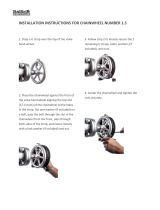
1. If the cable nipple is not located in to its housing in
the lever then simply align the slots in the cable adjuster
with the slot in the brake body and fit the nipple into
the housing. Pull the cable into position through the
slots and turn the adjuster sufficient to disrupt slot
alignment (take care the ferrule is located into the cable
adjuster.)
2. Ensure the fittings (lead pipe and rubber boot) are in
position at the brake end of the cable.
3. Loosen the brake pad retaining nut so the pad can
move freely then push the brake arm so that the pad
can be positioned with its surface parallel to the rim to
keep the pad away from the tyre (Take care to match
the curve of the rim with any curvature along the length
of the pads. Tighten the pad in position (6-8Nm). Repeat
on the left and on the right side.
1.
3.
2.
Nipple
Slot
Lead Pipe
Rubber
Boot
Reach Adjuster
Screw
Ferrule
Page 10
7.
4.
5a.
Brake Pipe
Hanger
Pinch
Bolt
2-3mm
65mm
5b.
Tension
Adjuster
4. Locate the brake cable wire into position behind
the pinch bolt (some have a hole to thread the wire
through). Loosely secure the wire in position.
5. Locate the curved lead pipe into the brake lead
pipe hanger. Loosen the pinch bolt and pull the wire
through so that the pads come into contact with
the rim surface (5a). Set the pads to have 2-3mm
of clearance to the rim on both sides (5b). Tighten
the pinch bolt securely (6-8Nm) and check that the
wire is not damaged or cut through. The distance
between the lead pipe tip and the pinch bolt should
not be less than 65mm. You can exchange positions
of the thick and thin washers behind the pads to
achieve this.
6. Test the brake function, the brake lever should
move through no more than approx 20% - 30% of
its travel before the pads are firmly against the rim.
7. If you find when you pull the brake lever that one
pad hits the rim before the other. You will need to
alter the spring tension in the brake arms. You can
increase spring tension by screwing the adjuster in
clockwise and reduce by turning anti clockwise. The
pad that hits first needs the tension reducing, or you
can increase the tension in the opposing arm ( judge
this by the relative tension adjuster positions). It is
wise to first check that the wheel is centrally located
in the frame or forks before commencing with this
adjustment.
8. New brake cables will stretch; this can be adjusted
by pulling more cable through the pinch bolt or by
using the cable adjuster at the lever. Take care if you
screw the adjuster outwards to return the adjuster
locking ring so it is firmly up against the brake lever
body. IT IS NOT SAFE TO RELY UPON THE THREAD OF
THE LEVER ALONE TO SUPPORT BRAKING FORCES.
Page 9
Page 10
Page 9
BRAKE MAINTENANCE
1. Check cables are corrosion free and lubricated to maintain smooth function.
2. Check all cables are free of kinks or frayed section, replace as necessary.
3. From time to time check all the retaining bolts are secure including those
of the pads.
4. Replace lost cable end protectors to avoid cables fraying.
5. To assure smooth braking, wheels must run true and be correctly adjusted, with the
rim brake tracks free from dents and kinks. The brake blocks should be in correct
alignment with the rim brake track. See your dealer if you are in any doubt
regarding wheel and brake adjustment.
6. We recommend that only genuine replacement parts are used for safety critical
components like brake friction pads and cables. if in doubt consult your retailer.
'V' BRAKE ADJUSTMENT
Although every effort has been made to ensure the brakes are set in a manner that
will ensure minimal re-adjustment prior to riding it is not possible to prevent transit
movement or disturbance when unpacking. In addition to the 5mm and 6mm allen key
wrenches and a multi metric spanner included with your cycle you will find the following
tools useful for correct assembly and adjustment of your cycle; a small adjustable wrench
(up to 20mm), a pair of pliers with wire cutting facility, a small cross cut screwdriver, and
a small flat blade screwdriver. For certain maintenance and replacement work specific
cycle tools are needed, if in any doubt contact your cycle supplier.
Below are simple instructions for general brake setting.
1. If the cable nipple is not located in to its housing in
the lever then simply align the slots in the cable adjuster
with the slot in the brake body and fit the nipple into
the housing. Pull the cable into position through the
slots and turn the adjuster sufficient to disrupt slot
alignment (take care the ferrule is located into the cable
adjuster.)
2. Ensure the fittings (lead pipe and rubber boot) are in
position at the brake end of the cable.
3. Loosen the brake pad retaining nut so the pad can
move freely then push the brake arm so that the pad
can be positioned with its surface parallel to the rim to
keep the pad away from the tyre (Take care to match
the curve of the rim with any curvature along the length
of the pads. Tighten the pad in position (6-8Nm). Repeat
on the left and on the right side.
1.
3.
2.
Nipple
Slot
Lead Pipe
Rubber
Boot
Reach Adjuster
Screw
Ferrule
Page 10
7.
4.
5a.
Brake Pipe
Hanger
Pinch
Bolt
2-3mm
65mm
5b.
Tension
Adjuster
4. Locate the brake cable wire into position behind
the pinch bolt (some have a hole to thread the wire
through). Loosely secure the wire in position.
5. Locate the curved lead pipe into the brake lead
pipe hanger. Loosen the pinch bolt and pull the wire
through so that the pads come into contact with
the rim surface (5a). Set the pads to have 2-3mm
of clearance to the rim on both sides (5b). Tighten
the pinch bolt securely (6-8Nm) and check that the
wire is not damaged or cut through. The distance
between the lead pipe tip and the pinch bolt should
not be less than 65mm. You can exchange positions
of the thick and thin washers behind the pads to
achieve this.
6. Test the brake function, the brake lever should
move through no more than approx 20% - 30% of
its travel before the pads are firmly against the rim.
7. If you find when you pull the brake lever that one
pad hits the rim before the other. You will need to
alter the spring tension in the brake arms. You can
increase spring tension by screwing the adjuster in
clockwise and reduce by turning anti clockwise. The
pad that hits first needs the tension reducing, or you
can increase the tension in the opposing arm ( judge
this by the relative tension adjuster positions). It is
wise to first check that the wheel is centrally located
in the frame or forks before commencing with this
adjustment.
8. New brake cables will stretch; this can be adjusted
by pulling more cable through the pinch bolt or by
using the cable adjuster at the lever. Take care if you
screw the adjuster outwards to return the adjuster
locking ring so it is firmly up against the brake lever
body. IT IS NOT SAFE TO RELY UPON THE THREAD OF
THE LEVER ALONE TO SUPPORT BRAKING FORCES.
Page 9
Page 10
Page 10
7.
4.
5a.
Brake Pipe
Hanger
Pinch
Bolt
2-3mm
65mm
5b.
Tension
Adjuster
4. Locate the brake cable wire into position behind
the pinch bolt (some have a hole to thread the wire
through). Loosely secure the wire in position.
5. Locate the curved lead pipe into the brake lead
pipe hanger. Loosen the pinch bolt and pull the wire
through so that the pads come into contact with
the rim surface (5a). Set the pads to have 2-3mm
of clearance to the rim on both sides (5b). Tighten
the pinch bolt securely (6-8Nm) and check that the
wire is not damaged or cut through. The distance
between the lead pipe tip and the pinch bolt should
not be less than 65mm. You can exchange positions
of the thick and thin washers behind the pads to
achieve this.
6. Test the brake function, the brake lever should
move through no more than approx 20% - 30% of
its travel before the pads are firmly against the rim.
7. If you find when you pull the brake lever that one
pad hits the rim before the other. You will need to
alter the spring tension in the brake arms. You can
increase spring tension by screwing the adjuster in
clockwise and reduce by turning anti clockwise. The
pad that hits first needs the tension reducing, or you
can increase the tension in the opposing arm ( judge
this by the relative tension adjuster positions). It is
wise to first check that the wheel is centrally located
in the frame or forks before commencing with this
adjustment.
8. New brake cables will stretch; this can be adjusted
by pulling more cable through the pinch bolt or by
using the cable adjuster at the lever. Take care if you
screw the adjuster outwards to return the adjuster
locking ring so it is firmly up against the brake lever
body. IT IS NOT SAFE TO RELY UPON THE THREAD OF
THE LEVER ALONE TO SUPPORT BRAKING FORCES.

Page 11
As the brake pads wear in normal use you will find that lever travel increase before the
pads are against the rim.
You can follow the adjustments outlined in point 7, 8 and 10 to take up this wear. Pads
should be replaced when they are worn to the ‘wear limit line’. If this is not indicated
or not visible you should replace the pads when you are either; unable to meet the
adjustment criteria above or the pad surface nodes are worn away over ANY of the pad
area.
PAD REPLACEMENT
Nodes
Replace when nodes worn
out over any surface
Brake systems that apply force through the direct action of friction material onto the
rim will of course create wear of the rim wall..
A thin v shaped groove is often cut into the braking surface of the rim. As the rim
wears away then this groove disappears indicating that the rim is becoming worn. You
should replace your rim before the safety groove disappears.
Some rims employ other methods to show when they are becoming seriously worn.
You should familiarise yourself with the method used on your bike. If in doubt consult
your retailer.
9. It is possible to alter the rest position of the brake lever by screwing in the reach
adjuster screw which pushes the lever nearer to the handlebars. If you utilise this
function take care to perform all the adjustments from your preferred rest position.
Be aware that this adjustment uses up brake lever potential travel and requires more
regular maintenance and fine adjustment of the brake system.
10. After all the adjustments are finished cut the excess cable from the end of the outer
wire and fit a cable end protector.
11. Before riding your cycle check for correct brake function.
12. We strongly recommend if you experience any difficulty with these adjustments that
you contact your supplier.
13. UNDER NO CIRCUMSTANCES SHOULD YOU RIDE YOUR CYCLE IF YOU SUSPECT THE
BRAKES ARE NOT PERFORMING IN A SAFE CORRECT MANNER. Always seek professional
advice from your supplier or cycle repairer should you have any doubts on this matter.
Page 12
CHAIN TENSION
If your cycle has a single rear gear sprocket (internal gears or single speed cycles). You
may need to adjust the chain tension from time to time or after rear wheel removal. To
adjust the chain tension correctly both wheel retaining nuts should be loose. Pull the
wheel back into the frame dropouts to take up the chain slack. Keep the wheel cen-
tral between the chainstays and alternately tighten the wheel retaining nuts, this will
help maintain the central position. The chain is correctly tensioned if there is between
4-10mm total of vertical play, any less and you risk tight spots in the chain any more and
the chain can become too loose and may lead to premature wear or failure.
BRAKE MAINTENANCE — Disc Brakes
You cycle may arrive with factory fitted disc brakes, the very latest in braking
technology.
There are two types as referred to below,
Mechanical disc brakes
These are operated by a standard cable and brake levers to actuate the brake pads
against the disc. These brakes will require periodical adjustment as the brake pads wear,
for detailed instructions on this adjustment please consult the brake specific leaflet
included with the cycle. If in any doubt please consult you dealer for further advice.
In addition you should always check brake function and adjustment regularly and ensure
the brake lever and brake cable are in perfect condition before riding. Do not touch the
disc brake rotor or calliper immediately after riding, as these may become hot!
Hydraulic disc brakes
These use dedicated brake levers, and brake fluid to actuate the brake pads against the
disc. Some types of disc brakes are self adjusting for wear, but some however require
periodical adjustment to compensate for pad wear. Please consult the brake specific
leaflet included with the cycle for more information. If in any doubt please consult your
dealer for further advice.
We recommend all maintenance is carried out by a competent mechanic at your local
dealer.
Regulary inspect the brake pads to ensure they have suffiecient brake material avail-
able for safe braking and look for any signs of uneven wear that could comprimise brake
function on your bike if in doubt consult your dealer.
Page 11 Page 12
Page 11
As the brake pads wear in normal use you will find that lever travel increase before the
pads are against the rim.
You can follow the adjustments outlined in point 7, 8 and 10 to take up this wear. Pads
should be replaced when they are worn to the ‘wear limit line’. If this is not indicated
or not visible you should replace the pads when you are either; unable to meet the
adjustment criteria above or the pad surface nodes are worn away over ANY of the pad
area.
PAD REPLACEMENT
Nodes
Replace when nodes worn
out over any surface
Brake systems that apply force through the direct action of friction material onto the
rim will of course create wear of the rim wall..
A thin v shaped groove is often cut into the braking surface of the rim. As the rim
wears away then this groove disappears indicating that the rim is becoming worn. You
should replace your rim before the safety groove disappears.
Some rims employ other methods to show when they are becoming seriously worn.
You should familiarise yourself with the method used on your bike. If in doubt consult
your retailer.
9. It is possible to alter the rest position of the brake lever by screwing in the reach
adjuster screw which pushes the lever nearer to the handlebars. If you utilise this
function take care to perform all the adjustments from your preferred rest position.
Be aware that this adjustment uses up brake lever potential travel and requires more
regular maintenance and fine adjustment of the brake system.
10. After all the adjustments are finished cut the excess cable from the end of the outer
wire and fit a cable end protector.
11. Before riding your cycle check for correct brake function.
12. We strongly recommend if you experience any difficulty with these adjustments that
you contact your supplier.
13. UNDER NO CIRCUMSTANCES SHOULD YOU RIDE YOUR CYCLE IF YOU SUSPECT THE
BRAKES ARE NOT PERFORMING IN A SAFE CORRECT MANNER. Always seek professional
advice from your supplier or cycle repairer should you have any doubts on this matter.
Page 12
CHAIN TENSION
If your cycle has a single rear gear sprocket (internal gears or single speed cycles). You
may need to adjust the chain tension from time to time or after rear wheel removal. To
adjust the chain tension correctly both wheel retaining nuts should be loose. Pull the
wheel back into the frame dropouts to take up the chain slack. Keep the wheel cen-
tral between the chainstays and alternately tighten the wheel retaining nuts, this will
help maintain the central position. The chain is correctly tensioned if there is between
4-10mm total of vertical play, any less and you risk tight spots in the chain any more and
the chain can become too loose and may lead to premature wear or failure.
BRAKE MAINTENANCE — Disc Brakes
You cycle may arrive with factory fitted disc brakes, the very latest in braking
technology.
There are two types as referred to below,
Mechanical disc brakes
These are operated by a standard cable and brake levers to actuate the brake pads
against the disc. These brakes will require periodical adjustment as the brake pads wear,
for detailed instructions on this adjustment please consult the brake specific leaflet
included with the cycle. If in any doubt please consult you dealer for further advice.
In addition you should always check brake function and adjustment regularly and ensure
the brake lever and brake cable are in perfect condition before riding. Do not touch the
disc brake rotor or calliper immediately after riding, as these may become hot!
Hydraulic disc brakes
These use dedicated brake levers, and brake fluid to actuate the brake pads against the
disc. Some types of disc brakes are self adjusting for wear, but some however require
periodical adjustment to compensate for pad wear. Please consult the brake specific
leaflet included with the cycle for more information. If in any doubt please consult your
dealer for further advice.
We recommend all maintenance is carried out by a competent mechanic at your local
dealer.
Regulary inspect the brake pads to ensure they have suffiecient brake material avail-
able for safe braking and look for any signs of uneven wear that could comprimise brake
function on your bike if in doubt consult your dealer.
Page 11 Page 12
Page 12
CHAIN TENSION
If your cycle has a single rear gear sprocket (internal gears or single speed cycles). You
may need to adjust the chain tension from time to time or after rear wheel removal. To
adjust the chain tension correctly both wheel retaining nuts should be loose. Pull the
wheel back into the frame dropouts to take up the chain slack. Keep the wheel cen-
tral between the chainstays and alternately tighten the wheel retaining nuts, this will
help maintain the central position. The chain is correctly tensioned if there is between
4-10mm total of vertical play, any less and you risk tight spots in the chain any more and
the chain can become too loose and may lead to premature wear or failure.
BRAKE MAINTENANCE — Disc Brakes
You cycle may arrive with factory fitted disc brakes, the very latest in braking
technology.
There are two types as referred to below,
Mechanical disc brakes
These are operated by a standard cable and brake levers to actuate the brake pads
against the disc. These brakes will require periodical adjustment as the brake pads wear,
for detailed instructions on this adjustment please consult the brake specific leaflet
included with the cycle. If in any doubt please consult you dealer for further advice.
In addition you should always check brake function and adjustment regularly and ensure
the brake lever and brake cable are in perfect condition before riding. Do not touch the
disc brake rotor or calliper immediately after riding, as these may become hot!
Hydraulic disc brakes
These use dedicated brake levers, and brake fluid to actuate the brake pads against the
disc. Some types of disc brakes are self adjusting for wear, but some however require
periodical adjustment to compensate for pad wear. Please consult the brake specific
leaflet included with the cycle for more information. If in any doubt please consult your
dealer for further advice.
We recommend all maintenance is carried out by a competent mechanic at your local
dealer.
Regulary inspect the brake pads to ensure they have suffiecient brake material avail-
able for safe braking and look for any signs of uneven wear that could comprimise brake
function on your bike if in doubt consult your dealer.

Page 13
GATES CARBON DRIVETM (GCD)
Warnings:
1. The GCD products are exclusively OEM parts or replacement parts for manufacturers
of bicycles!
2. The GCD may only be installed at a suitably manufactured, prepared and tested frame!
3. The manufacturer is responsible for the professional assembling of the product!
4. The manufacturer is required to upgrade his manuals with the GCD
warnings and instructions.
5. Only use the tools of the UT GmbH or GATES for the assembly and testing of the belt
tension!
6. The manufacturer is responsible for the selection of the required parts, according to
the respective kind of use (applications)!
7. The GCD should not be used under extreme conditions (mud, clay, snow). This can lead
to excessive wear, or also damage the belt!
8. The GCD can not be used above its wear limit!
9. The use of an idler pulley is forbidden!
10.The installation or replacement of worn parts is carried out by qualified
personnel only!
11. Because of safety reasons, we can not take back a shipped belt for credit note!
12.An already installed GCD product can not be taken back for credit note!
13.Please check first the manuals here: http://manual.carbondrive.net (Rohloff-Manual)!
14.Please check our warranty here: http://manual.carbondrive.net !
If you have further questions concerning the Gates Carbon Drive after reading the
information above, please contact your dealer or us.
http://manual.carbondrive.net
Crimping Twisting Back
bending
Inverting Zip tieing
Page 14
DERAILLEUR GEARS INTRODUCTION
The derailleur gear is so named because it works on the derailing principle to move the
chain from one sprocket to another. The number of gears is determined by multiplying
the number of sprockets on the rear freewheel by the number of chainrings on the front
crank set.
By using different combinations of sprocket and chainwheel sizes, a wide range of gear
ratios are available. The highest gear is when the large chainwheel is coupled with the
small sprocket and the lowest gear is when the small chainwheel is combined with the
largest rear sprocket.
DERAILLEUR GEAR MAINTENANCE
To help ensure that your derailleur gear works efficiently and to prolong its life, it must
be kept clean and free from excess dirt build up and should be properly lubricated.
GEAR CHANGING
The rider’s left gear lever controls the front derailleur and chain wheels.
The right gear lever controls the rear derailleur and sprockets.
The large rear sprockets generate low gears for hill climbing. The small rear sprockets
develop high gear ratios for speed work and downhill riding.
The small front chainring produces low gear ratios while the larger front chainrings
produce higher gear ratios.
To operate your derailleur gear system efficiently and reduce damage, wear and reduce
noise to a minimum, avoid using the maximum crossover gear ratios of large chainring/
large rear sprocket, small chainring/small rear sprocket.
Caution: For positive gear selection, observe these four precautions:
1. Change only when pedals and wheels are moving in a forward motion.
2. Reduce pedal pressure while changing gears.
3. Never back pedal when changing gear.
4. Never force the gear levers.
Gear selection should be made in anticipation of need since forward motion of the
bicycle is required when changing gear. It is advisable to change to a low gear before
stopping in order to be in the proper gear when you start up. On hills, change gear early
while still maintaining forward pedalling speed.
GEAR ADJUSTMENT
Follow the specific instructions for your cycle system included on a seperate leaflet. The
following tips may be of assistance in diagnosis of the fault and will be useful information
to pass on to whoever is adjusting the gears.
Page 13
GATES CARBON DRIVETM (GCD)
Warnings:
1. The GCD products are exclusively OEM parts or replacement parts for manufacturers
of bicycles!
2. The GCD may only be installed at a suitably manufactured, prepared and tested frame!
3. The manufacturer is responsible for the professional assembling of the product!
4. The manufacturer is required to upgrade his manuals with the GCD
warnings and instructions.
5. Only use the tools of the UT GmbH or GATES for the assembly and testing of the belt
tension!
6. The manufacturer is responsible for the selection of the required parts, according to
the respective kind of use (applications)!
7. The GCD should not be used under extreme conditions (mud, clay, snow). This can lead
to excessive wear, or also damage the belt!
8. The GCD can not be used above its wear limit!
9. The use of an idler pulley is forbidden!
10.The installation or replacement of worn parts is carried out by qualified
personnel only!
11. Because of safety reasons, we can not take back a shipped belt for credit note!
12.An already installed GCD product can not be taken back for credit note!
13.Please check first the manuals here: http://manual.carbondrive.net (Rohloff-Manual)!
14.Please check our warranty here: http://manual.carbondrive.net !
If you have further questions concerning the Gates Carbon Drive after reading the
information above, please contact your dealer or us.
http://manual.carbondrive.net
Crimping Twisting Back
bending
Inverting Zip tieing
Page 13 Page 14
Page 13
GATES CARBON DRIVETM (GCD)
Warnings:
1. The GCD products are exclusively OEM parts or replacement parts for manufacturers
of bicycles!
2. The GCD may only be installed at a suitably manufactured, prepared and tested frame!
3. The manufacturer is responsible for the professional assembling of the product!
4. The manufacturer is required to upgrade his manuals with the GCD
warnings and instructions.
5. Only use the tools of the UT GmbH or GATES for the assembly and testing of the belt
tension!
6. The manufacturer is responsible for the selection of the required parts, according to
the respective kind of use (applications)!
7. The GCD should not be used under extreme conditions (mud, clay, snow). This can lead
to excessive wear, or also damage the belt!
8. The GCD can not be used above its wear limit!
9. The use of an idler pulley is forbidden!
10.The installation or replacement of worn parts is carried out by qualified
personnel only!
11. Because of safety reasons, we can not take back a shipped belt for credit note!
12.An already installed GCD product can not be taken back for credit note!
13.Please check first the manuals here: http://manual.carbondrive.net (Rohloff-Manual)!
14.Please check our warranty here: http://manual.carbondrive.net !
If you have further questions concerning the Gates Carbon Drive after reading the
information above, please contact your dealer or us.
http://manual.carbondrive.net
Crimping Twisting Back
bending
Inverting Zip tieing
Page 14
DERAILLEUR GEARS INTRODUCTION
The derailleur gear is so named because it works on the derailing principle to move the
chain from one sprocket to another. The number of gears is determined by multiplying
the number of sprockets on the rear freewheel by the number of chainrings on the front
crank set.
By using different combinations of sprocket and chainwheel sizes, a wide range of gear
ratios are available. The highest gear is when the large chainwheel is coupled with the
small sprocket and the lowest gear is when the small chainwheel is combined with the
largest rear sprocket.
DERAILLEUR GEAR MAINTENANCE
To help ensure that your derailleur gear works efficiently and to prolong its life, it must
be kept clean and free from excess dirt build up and should be properly lubricated.
GEAR CHANGING
The rider’s left gear lever controls the front derailleur and chain wheels.
The right gear lever controls the rear derailleur and sprockets.
The large rear sprockets generate low gears for hill climbing. The small rear sprockets
develop high gear ratios for speed work and downhill riding.
The small front chainring produces low gear ratios while the larger front chainrings
produce higher gear ratios.
To operate your derailleur gear system efficiently and reduce damage, wear and reduce
noise to a minimum, avoid using the maximum crossover gear ratios of large chainring/
large rear sprocket, small chainring/small rear sprocket.
Caution: For positive gear selection, observe these four precautions:
1. Change only when pedals and wheels are moving in a forward motion.
2. Reduce pedal pressure while changing gears.
3. Never back pedal when changing gear.
4. Never force the gear levers.
Gear selection should be made in anticipation of need since forward motion of the
bicycle is required when changing gear. It is advisable to change to a low gear before
stopping in order to be in the proper gear when you start up. On hills, change gear early
while still maintaining forward pedalling speed.
GEAR ADJUSTMENT
Follow the specific instructions for your cycle system included on a seperate leaflet. The
following tips may be of assistance in diagnosis of the fault and will be useful information
to pass on to whoever is adjusting the gears.
Page 13
GATES CARBON DRIVETM (GCD)
Warnings:
1. The GCD products are exclusively OEM parts or replacement parts for manufacturers
of bicycles!
2. The GCD may only be installed at a suitably manufactured, prepared and tested frame!
3. The manufacturer is responsible for the professional assembling of the product!
4. The manufacturer is required to upgrade his manuals with the GCD
warnings and instructions.
5. Only use the tools of the UT GmbH or GATES for the assembly and testing of the belt
tension!
6. The manufacturer is responsible for the selection of the required parts, according to
the respective kind of use (applications)!
7. The GCD should not be used under extreme conditions (mud, clay, snow). This can lead
to excessive wear, or also damage the belt!
8. The GCD can not be used above its wear limit!
9. The use of an idler pulley is forbidden!
10.The installation or replacement of worn parts is carried out by qualified
personnel only!
11. Because of safety reasons, we can not take back a shipped belt for credit note!
12.An already installed GCD product can not be taken back for credit note!
13.Please check first the manuals here: http://manual.carbondrive.net (Rohloff-Manual)!
14.Please check our warranty here: http://manual.carbondrive.net !
If you have further questions concerning the Gates Carbon Drive after reading the
information above, please contact your dealer or us.
http://manual.carbondrive.net
Crimping Twisting Back
bending
Inverting Zip tieing
Page 13 Page 14

Page 13
GATES CARBON DRIVETM (GCD)
Warnings:
1. The GCD products are exclusively OEM parts or replacement parts for manufacturers
of bicycles!
2. The GCD may only be installed at a suitably manufactured, prepared and tested frame!
3. The manufacturer is responsible for the professional assembling of the product!
4. The manufacturer is required to upgrade his manuals with the GCD
warnings and instructions.
5. Only use the tools of the UT GmbH or GATES for the assembly and testing of the belt
tension!
6. The manufacturer is responsible for the selection of the required parts, according to
the respective kind of use (applications)!
7. The GCD should not be used under extreme conditions (mud, clay, snow). This can lead
to excessive wear, or also damage the belt!
8. The GCD can not be used above its wear limit!
9. The use of an idler pulley is forbidden!
10.The installation or replacement of worn parts is carried out by qualified
personnel only!
11. Because of safety reasons, we can not take back a shipped belt for credit note!
12.An already installed GCD product can not be taken back for credit note!
13.Please check first the manuals here: http://manual.carbondrive.net (Rohloff-Manual)!
14.Please check our warranty here: http://manual.carbondrive.net !
If you have further questions concerning the Gates Carbon Drive after reading the
information above, please contact your dealer or us.
http://manual.carbondrive.net
Crimping Twisting Back
bending
Inverting Zip tieing
Page 14
DERAILLEUR GEARS INTRODUCTION
The derailleur gear is so named because it works on the derailing principle to move the
chain from one sprocket to another. The number of gears is determined by multiplying
the number of sprockets on the rear freewheel by the number of chainrings on the front
crank set.
By using different combinations of sprocket and chainwheel sizes, a wide range of gear
ratios are available. The highest gear is when the large chainwheel is coupled with the
small sprocket and the lowest gear is when the small chainwheel is combined with the
largest rear sprocket.
DERAILLEUR GEAR MAINTENANCE
To help ensure that your derailleur gear works efficiently and to prolong its life, it must
be kept clean and free from excess dirt build up and should be properly lubricated.
GEAR CHANGING
The rider’s left gear lever controls the front derailleur and chain wheels.
The right gear lever controls the rear derailleur and sprockets.
The large rear sprockets generate low gears for hill climbing. The small rear sprockets
develop high gear ratios for speed work and downhill riding.
The small front chainring produces low gear ratios while the larger front chainrings
produce higher gear ratios.
To operate your derailleur gear system efficiently and reduce damage, wear and reduce
noise to a minimum, avoid using the maximum crossover gear ratios of large chainring/
large rear sprocket, small chainring/small rear sprocket.
Caution: For positive gear selection, observe these four precautions:
1. Change only when pedals and wheels are moving in a forward motion.
2. Reduce pedal pressure while changing gears.
3. Never back pedal when changing gear.
4. Never force the gear levers.
Gear selection should be made in anticipation of need since forward motion of the
bicycle is required when changing gear. It is advisable to change to a low gear before
stopping in order to be in the proper gear when you start up. On hills, change gear early
while still maintaining forward pedalling speed.
GEAR ADJUSTMENT
Follow the specific instructions for your cycle system included on a seperate leaflet. The
following tips may be of assistance in diagnosis of the fault and will be useful information
to pass on to whoever is adjusting the gears.
Page 13
GATES CARBON DRIVETM (GCD)
Warnings:
1. The GCD products are exclusively OEM parts or replacement parts for manufacturers
of bicycles!
2. The GCD may only be installed at a suitably manufactured, prepared and tested frame!
3. The manufacturer is responsible for the professional assembling of the product!
4. The manufacturer is required to upgrade his manuals with the GCD
warnings and instructions.
5. Only use the tools of the UT GmbH or GATES for the assembly and testing of the belt
tension!
6. The manufacturer is responsible for the selection of the required parts, according to
the respective kind of use (applications)!
7. The GCD should not be used under extreme conditions (mud, clay, snow). This can lead
to excessive wear, or also damage the belt!
8. The GCD can not be used above its wear limit!
9. The use of an idler pulley is forbidden!
10.The installation or replacement of worn parts is carried out by qualified
personnel only!
11. Because of safety reasons, we can not take back a shipped belt for credit note!
12.An already installed GCD product can not be taken back for credit note!
13.Please check first the manuals here: http://manual.carbondrive.net (Rohloff-Manual)!
14.Please check our warranty here: http://manual.carbondrive.net !
If you have further questions concerning the Gates Carbon Drive after reading the
information above, please contact your dealer or us.
http://manual.carbondrive.net
Crimping Twisting Back
bending
Inverting Zip tieing
Page 13 Page 14
Page 14
DERAILLEUR GEARS INTRODUCTION
The derailleur gear is so named because it works on the derailing principle to move the
chain from one sprocket to another. The number of gears is determined by multiplying
the number of sprockets on the rear freewheel by the number of chainrings on the front
crank set.
By using different combinations of sprocket and chainwheel sizes, a wide range of gear
ratios are available. The highest gear is when the large chainwheel is coupled with the
small sprocket and the lowest gear is when the small chainwheel is combined with the
largest rear sprocket.
DERAILLEUR GEAR MAINTENANCE
To help ensure that your derailleur gear works efficiently and to prolong its life, it must
be kept clean and free from excess dirt build up and should be properly lubricated.
GEAR CHANGING
The rider’s left gear lever controls the front derailleur and chain wheels.
The right gear lever controls the rear derailleur and sprockets.
The large rear sprockets generate low gears for hill climbing. The small rear sprockets
develop high gear ratios for speed work and downhill riding.
The small front chainring produces low gear ratios while the larger front chainrings
produce higher gear ratios.
To operate your derailleur gear system efficiently and reduce damage, wear and reduce
noise to a minimum, avoid using the maximum crossover gear ratios of large chainring/
large rear sprocket, small chainring/small rear sprocket.
Caution: For positive gear selection, observe these four precautions:
1. Change only when pedals and wheels are moving in a forward motion.
2. Reduce pedal pressure while changing gears.
3. Never back pedal when changing gear.
4. Never force the gear levers.
Gear selection should be made in anticipation of need since forward motion of the
bicycle is required when changing gear. It is advisable to change to a low gear before
stopping in order to be in the proper gear when you start up. On hills, change gear early
while still maintaining forward pedalling speed.
GEAR ADJUSTMENT
Follow the specific instructions for your cycle system included on a seperate leaflet. The
following tips may be of assistance in diagnosis of the fault and will be useful information
to pass on to whoever is adjusting the gears.
Page 13
GATES CARBON DRIVETM (GCD)
Warnings:
1. The GCD products are exclusively OEM parts or replacement parts for manufacturers
of bicycles!
2. The GCD may only be installed at a suitably manufactured, prepared and tested frame!
3. The manufacturer is responsible for the professional assembling of the product!
4. The manufacturer is required to upgrade his manuals with the GCD
warnings and instructions.
5. Only use the tools of the UT GmbH or GATES for the assembly and testing of the belt
tension!
6. The manufacturer is responsible for the selection of the required parts, according to
the respective kind of use (applications)!
7. The GCD should not be used under extreme conditions (mud, clay, snow). This can lead
to excessive wear, or also damage the belt!
8. The GCD can not be used above its wear limit!
9. The use of an idler pulley is forbidden!
10.The installation or replacement of worn parts is carried out by qualified
personnel only!
11. Because of safety reasons, we can not take back a shipped belt for credit note!
12.An already installed GCD product can not be taken back for credit note!
13.Please check first the manuals here: http://manual.carbondrive.net (Rohloff-Manual)!
14.Please check our warranty here: http://manual.carbondrive.net !
If you have further questions concerning the Gates Carbon Drive after reading the
information above, please contact your dealer or us.
http://manual.carbondrive.net
Crimping Twisting Back
bending
Inverting Zip tieing
Page 13 Page 14

Page 15
REAR
GEAR ADJUSTMENT
We strongly suggest that you return your bicycle to your dealer for gear adjustments. However, in case of emergency and
for minor adjustments, the fault finding chart should help you.
Finding and Correcting Problems
Problem
1. Changing from gear selected without touch
-
ing gear lever
2. Chain throwing off the small sprocket toward
frame or not riding on sprocket or not reaching
large sprocket.
3. Chain throwing off the large sprocket toward
wheel or not riding on sprocket or not reaching
large sprocket
4. Gear lever engages lever stop before low
gear is obtained.
Cause
1. Improper tension on gear levers.
2. Cable slip
1. Incorrect setting of high gear adjustment
screw.
1. Incorrect setting of low gear adjustment
screw
1. Too much slack in cable
Cure
Tighten gear tension lever screws.
Tighten cable pinch bolt.
Readjust
Readjust
Readjust cable
WARNING
Do not tighten so tight you unable to
change gear. Do not lubricate as levers work
on friction.
Ensure cable adjustment is correct before
tightening. Ensure tension in gear cable is
not acting as a stop.
Ensure tension in gear cable is not acting
as a stop.
Ensure that the chain never derails towards
the wheel as extensive damage can be
incurred.
Ensure cable is not used as a stop
1. Changing from large to small chainwheel
sprocket without touching gear lever
2. Chain throwing off large chainwheel or not
engaging chainwheel
3. Chainwheel throwing off small chainwheel or
not engaging chainwheel
1. Improper tension on gear levers
1 Incorrect setting of outer chainwheel adjust
screw
1 Incorrect setting of inner chainwheel adjust
screw
Tighten gear tension lever screws.
Readjust.
Readjust.
Do not tighten so tight you are unable to
change gear.
Do not lubricate as levers work on friction
FRONT
Page 16
TYRE CARE AND WHEEL ADJUSTMENTS CONTINUED
QUICK RELEASE FRONT WHEEL
1. To remove the front wheel, first release the front wheel brake. The release the
quick-release lever on the axle and pull the wheel from the forks.
2. To install, fit wheel into forks with quick release lever on the left side. Close quick-
release, and tighten adjuster until snug. Release quick-release lever and further
tighten adjuster approximately 3/4 of a turn. Lock and check that the quick-
release has embossed the fork ends. It may be necessary to tighten or loosen
the adjuster slightly. Make certain to reset the quick-release front brake to
ensure proper operation.
3. Wheel must be clear frame and fork by at least 1/16".
4. The wheel should turn freely and have very little side-play.
5. Check quick-release lever is correct and fully locked position before each ride.
Closed
Open
Spring
Spring
Adjusting nut
Quick Release Lever
Locked position
Retaining Device
*Warning! Do not attempt to ride the cycle until you are absolutely sure that the quick release
lever is fully closed and securely tightened.
QUICK RELEASE REAR WHEEL
Operation and adjustment is as the rear but we recommend that you select the smallest
chainring and rear freewheel sprocket as this will give you the most free chain and allow
you to manouvere the wheel out of the rear of the frame with minimum interference
from the drive system.
Page 15
Page 16
Page 15
REAR
GEAR ADJUSTMENT
We strongly suggest that you return your bicycle to your dealer for gear adjustments. However, in case of emergency and
for minor adjustments, the fault finding chart should help you.
Finding and Correcting Problems
Problem
1. Changing from gear selected without touch-
ing gear lever
2. Chain throwing off the small sprocket toward
frame or not riding on sprocket or not reaching
large sprocket.
3. Chain throwing off the large sprocket toward
wheel or not riding on sprocket or not reaching
large sprocket
4. Gear lever engages lever stop before low
gear is obtained.
Cause
1. Improper tension on gear levers.
2. Cable slip
1. Incorrect setting of high gear adjustment
screw.
1. Incorrect setting of low gear adjustment
screw
1. Too much slack in cable
Cure
Tighten gear tension lever screws.
Tighten cable pinch bolt.
Readjust
Readjust
Readjust cable
WARNING
Do not tighten so tight you unable to
change gear. Do not lubricate as levers work
on friction.
Ensure cable adjustment is correct before
tightening. Ensure tension in gear cable is
not acting as a stop.
Ensure tension in gear cable is not acting
as a stop.
Ensure that the chain never derails towards
the wheel as extensive damage can be
incurred.
Ensure cable is not used as a stop
1. Changing from large to small chainwheel
sprocket without touching gear lever
2. Chain throwing off large chainwheel or not
engaging chainwheel
3. Chainwheel throwing off small chainwheel or
not engaging chainwheel
1. Improper tension on gear levers
1 Incorrect setting of outer chainwheel adjust
screw
1 Incorrect setting of inner chainwheel adjust
screw
Tighten gear tension lever screws.
Readjust.
Readjust.
Do not tighten so tight you are unable to
change gear.
Do not lubricate as levers work on friction
FRONT

Page 15
REAR
GEAR ADJUSTMENT
We strongly suggest that you return your bicycle to your dealer for gear adjustments. However, in case of emergency and
for minor adjustments, the fault finding chart should help you.
Finding and Correcting Problems
Problem
1. Changing from gear selected without touch
-
ing gear lever
2. Chain throwing off the small sprocket toward
frame or not riding on sprocket or not reaching
large sprocket.
3. Chain throwing off the large sprocket toward
wheel or not riding on sprocket or not reaching
large sprocket
4. Gear lever engages lever stop before low
gear is obtained.
Cause
1. Improper tension on gear levers.
2. Cable slip
1. Incorrect setting of high gear adjustment
screw.
1. Incorrect setting of low gear adjustment
screw
1. Too much slack in cable
Cure
Tighten gear tension lever screws.
Tighten cable pinch bolt.
Readjust
Readjust
Readjust cable
WARNING
Do not tighten so tight you unable to
change gear. Do not lubricate as levers work
on friction.
Ensure cable adjustment is correct before
tightening. Ensure tension in gear cable is
not acting as a stop.
Ensure tension in gear cable is not acting
as a stop.
Ensure that the chain never derails towards
the wheel as extensive damage can be
incurred.
Ensure cable is not used as a stop
1. Changing from large to small chainwheel
sprocket without touching gear lever
2. Chain throwing off large chainwheel or not
engaging chainwheel
3. Chainwheel throwing off small chainwheel or
not engaging chainwheel
1. Improper tension on gear levers
1 Incorrect setting of outer chainwheel adjust
screw
1 Incorrect setting of inner chainwheel adjust
screw
Tighten gear tension lever screws.
Readjust.
Readjust.
Do not tighten so tight you are unable to
change gear.
Do not lubricate as levers work on friction
FRONT
Page 16
TYRE CARE AND WHEEL ADJUSTMENTS CONTINUED
QUICK RELEASE FRONT WHEEL
1. To remove the front wheel, first release the front wheel brake. The release the
quick-release lever on the axle and pull the wheel from the forks.
2. To install, fit wheel into forks with quick release lever on the left side. Close quick-
release, and tighten adjuster until snug. Release quick-release lever and further
tighten adjuster approximately 3/4 of a turn. Lock and check that the quick-
release has embossed the fork ends. It may be necessary to tighten or loosen
the adjuster slightly. Make certain to reset the quick-release front brake to
ensure proper operation.
3. Wheel must be clear frame and fork by at least 1/16".
4. The wheel should turn freely and have very little side-play.
5. Check quick-release lever is correct and fully locked position before each ride.
Closed
Open
Spring
Spring
Adjusting nut
Quick Release Lever
Locked position
Retaining Device
*Warning! Do not attempt to ride the cycle until you are absolutely sure that the quick release
lever is fully closed and securely tightened.
QUICK RELEASE REAR WHEEL
Operation and adjustment is as the rear but we recommend that you select the smallest
chainring and rear freewheel sprocket as this will give you the most free chain and allow
you to manouvere the wheel out of the rear of the frame with minimum interference
from the drive system.
Page 15
Page 16
Page 16
TYRE CARE AND WHEEL ADJUSTMENTS CONTINUED
QUICK RELEASE FRONT WHEEL
1. To remove the front wheel, first release the front wheel brake. The release the
quick-release lever on the axle and pull the wheel from the forks.
2.
To install, fit wheel into forks with quick release lever on the left side. Close quick-
release, and tighten adjuster until snug. Release quick-release lever and further
tighten adjuster approximately 3/4 of a turn. Lock and check that the quick-
release has embossed the fork ends. It may be necessary to tighten or loosen
the adjuster slightly. Make certain to reset the quick-release front brake to
ensure proper operation.
3. Wheel must be clear frame and fork by at least 1/16".
4. The wheel should turn freely and have very little side-play.
5. Check quick-release lever is correct and fully locked position before each ride.
Closed
Open
Spring
Spring
Adjusting nut
Quick Release Lever
Locked position
Retaining Device
*Warning! Do not attempt to ride the cycle until you are absolutely sure that the quick release
lever is fully closed and securely tightened.
QUICK RELEASE REAR WHEEL
Operation and adjustment is as the rear but we recommend that you select the smallest
chainring and rear freewheel sprocket as this will give you the most free chain and allow
you to manouvere the wheel out of the rear of the frame with minimum interference
from the drive system.

Page 17
STANDARD WHEEL ADJUSTMENT & REMOVAL
To Remove Rear Wheel
Move the chain onto the smallest rear sprocket. Disengage the brake quick release lever
if your bicycle is so equipped. Loosen both axle nuts by turning in a counter clockwise
direction. Pull the derailleur mechanism gear for additional clearance. Remove the rear
wheel by sliding forward and out of the frame.
To install wheel, locate the top section of the chain on the small sprocket and replace
the wheel into the frame by pushing back and centralising between the chainstays.
While holding the wheel in this position, tighten the axle nuts in a clockwise direction.
The wheel should turn freely and have very little side play.
Reset rear brake quick release mechanism and check brake for proper operation.
To Remove Front Wheel
Remove axle nuts, washers, and axle retention device if fitted. The axle cone bearing
adjustment should permit smooth rotation of wheel. Cone locknut should be securely
fastened against axle cone to prevent loosening. Place the front wheel between the
fork blades with axle retention device and the projecting prongs of the retention device
securely fitting the slot in the fork or with standard washers securely placed in position
on to the wheel axle in the place of the retention washer. Replace locking washers and
nuts at both ends gradually and alternately in order to keep the wheel centered.
Caution:
Front wheel must be installed with retention devices securely placed into slots of fork
blades or washers if fitted. This will ensure positive locking of front wheel to front
fork.
Nut
Nut
Retention
device or washer
Retention
device or washer
Axle
Nut
Front Hub
Cone
Cone Locknut
Retention washer
(if fitted)
Front Fork
COTTERLESS CRANKS ADJUSTMENT
IMPORTANT
It is strongly recommended that the tightness of the nuts be checked after the first
two weeks of use and a maximum of three monthly intervals thereafter. Failure to do
so may cause permanent damage to the precision made components.
The adjustment should be made using a torque wrench fitted with a suitably sized
spanner having first removed the dust cap. Torque setting 38Nm (320 Ibs./ ins.) (30
lbs./ ft.)
BIKE CARE
Page 18
Page 17 Page 18
Page 17
STANDARD WHEEL ADJUSTMENT & REMOVAL
To Remove Rear Wheel
Move the chain onto the smallest rear sprocket. Disengage the brake quick release lever
if your bicycle is so equipped. Loosen both axle nuts by turning in a counter clockwise
direction. Pull the derailleur mechanism gear for additional clearance. Remove the rear
wheel by sliding forward and out of the frame.
To install wheel, locate the top section of the chain on the small sprocket and replace
the wheel into the frame by pushing back and centralising between the chainstays.
While holding the wheel in this position, tighten the axle nuts in a clockwise direction.
The wheel should turn freely and have very little side play.
Reset rear brake quick release mechanism and check brake for proper operation.
To Remove Front Wheel
Remove axle nuts, washers, and axle retention device if fitted. The axle cone bearing
adjustment should permit smooth rotation of wheel. Cone locknut should be securely
fastened against axle cone to prevent loosening. Place the front wheel between the
fork blades with axle retention device and the projecting prongs of the retention device
securely fitting the slot in the fork or with standard washers securely placed in position
on to the wheel axle in the place of the retention washer. Replace locking washers and
nuts at both ends gradually and alternately in order to keep the wheel centered.
Caution:
Front wheel must be installed with retention devices securely placed into slots of fork
blades or washers if fitted. This will ensure positive locking of front wheel to front
fork.
Nut
Nut
Retention
device or washer
Retention
device or washer
Axle
Nut
Front Hub
Cone
Cone Locknut
Retention washer
(if fitted)
Front Fork
COTTERLESS CRANKS ADJUSTMENT
IMPORTANT
It is strongly recommended that the tightness of the nuts be checked after the first
two weeks of use and a maximum of three monthly intervals thereafter. Failure to do
so may cause permanent damage to the precision made components.
The adjustment should be made using a torque wrench fitted with a suitably sized
spanner having first removed the dust cap. Torque setting 38Nm (320 Ibs./ ins.) (30
lbs./ ft.)
BIKE CARE
Page 18
Page 17
Page 18

Page 19
GENERAL MAINTENANCE
WARNING: As with all mechanical components, the bicycle is subjected to wear and high
stresses. Different materials and components may react to wear or stress fatique in
different ways. If the design life of a component has been exceeded, it may suddenly
fail possibly causing injuries to the rider. Any form of crack, scratched or change of
colouring in highly stressed areas indicate that the life of the components has been
reached and it should be replaced. We recommend that only genuine replacement parts
are used for safety critical components.
CHAIN MAINTENANCE
When you hear the disconcerting scrunch of “chain sucking” and it feels as if a stick has
been jammed through your chainrings, stop pedalling immediately. Get off and turn the
crank backward to free the chain. Otherwise, you risk damage to the chain, chainring,
and chainstay.
Extreme chain angles , such as combining the largest rear cog with the large chainring
(or smallest cog with the small chainring), may never run quietly or smoothly, which is
one reason they shouldn’t be used. Another reason not to use these gear combinations:
It could cause additional wear on your drivetrain.
If possible, lube your chain 24 hours before riding. This will allow the lube’s liquid carrier
to evaporate and keep your drivetrain cleaner. We recommend to lube the chain after
every 4th ride.
Hose your bike after riding in the rain to remove most of the grit. Then dry it with a
towel, and spray lubrication into derailleur and brake pivot points and where cables
enter or exit their housings.
The most important rule of mountain bike maintenance is frequent cleaning. Dirt
acts as a grinding compound when it gets between moving parts. In muddy or sandy
conditions, hose down the bike after every ride.
WHEELS AND TYRES
Carry a patch kit and a spare tube, so you’re not hopelessly stranded if you have two
flats on a ride. Also, carry a spare tube in the rain. Flats occur more frequently, and it’s
difficult to apply patches when it’s wet.
The patches in most tire repair kits have foil on one side and plastic on the other. the
surface under the foil goes against the tube( after glue has been applied) and then the
plastic is peeled off.
When a tire is properly installed, its bead (the thin line molded into the rubber just above
the rim) should not bob when the wheel spins. However, if the line between the tyre’s
side wall and black tread wobbles, don’t worry-most tires have some irregularity and it
won’t affect performance.
At least once a month, inspect each tyre’s tread for embedded glass or other debris.
Potential puncture producers can often be removed before they work through the tire
casing to the tube.
When fixing a flat, carefully feel around the inside of the tire. Whatever caused the
puncture may still be lodged through the tread, ready to strike again.
Page 20
Page 19
Page 20
Page 19
GENERAL MAINTENANCE
WARNING: As with all mechanical components, the bicycle is subjected to wear and high
stresses. Different materials and components may react to wear or stress fatique in
different ways. If the design life of a component has been exceeded, it may suddenly
fail possibly causing injuries to the rider. Any form of crack, scratched or change of
colouring in highly stressed areas indicate that the life of the components has been
reached and it should be replaced. We recommend that only genuine replacement parts
are used for safety critical components.
CHAIN MAINTENANCE
When you hear the disconcerting scrunch of “chain sucking” and it feels as if a stick has
been jammed through your chainrings, stop pedalling immediately. Get off and turn the
crank backward to free the chain. Otherwise, you risk damage to the chain, chainring,
and chainstay.
Extreme chain angles , such as combining the largest rear cog with the large chainring
(or smallest cog with the small chainring), may never run quietly or smoothly, which is
one reason they shouldn’t be used. Another reason not to use these gear combinations:
It could cause additional wear on your drivetrain.
If possible, lube your chain 24 hours before riding. This will allow the lube’s liquid carrier
to evaporate and keep your drivetrain cleaner. We recommend to lube the chain after
every 4th ride.
Hose your bike after riding in the rain to remove most of the grit. Then dry it with a
towel, and spray lubrication into derailleur and brake pivot points and where cables
enter or exit their housings.
The most important rule of mountain bike maintenance is frequent cleaning. Dirt
acts as a grinding compound when it gets between moving parts. In muddy or sandy
conditions, hose down the bike after every ride.
WHEELS AND TYRES
Carry a patch kit and a spare tube, so you’re not hopelessly stranded if you have two
flats on a ride. Also, carry a spare tube in the rain. Flats occur more frequently, and it’s
difficult to apply patches when it’s wet.
The patches in most tire repair kits have foil on one side and plastic on the other. the
surface under the foil goes against the tube( after glue has been applied) and then the
plastic is peeled off.
When a tire is properly installed, its bead (the thin line molded into the rubber just above
the rim) should not bob when the wheel spins. However, if the line between the tyre’s
side wall and black tread wobbles, don’t worry-most tires have some irregularity and it
won’t affect performance.
At least once a month, inspect each tyre’s tread for embedded glass or other debris.
Potential puncture producers can often be removed before they work through the tire
casing to the tube.
When fixing a flat, carefully feel around the inside of the tire. Whatever caused the
puncture may still be lodged through the tread, ready to strike again.
/