Supermicro SuperChassis 842TQ-665B User manual
- Category
- Computer cases
- Type
- User manual
This manual is also suitable for

SC842 Chassis
Series
SC842TQ-865B SC842TQ-665B
SC842i-500B
USER’S MANUAL
1.0b
SUPER
®

SC842 Chassis Manual
ii
Manual Revision 1.0b
Release Date: September 28, 2011
The information in this User’s Manual has been carefully reviewed and is believed to be accurate.
The vendor assumes no responsibility for any inaccuracies that may be contained in this document,
makes no commitment to update or to keep current the information in this manual, or to notify any
person or organization of the updates. Please Note: For the most up-to-date version of this
manual, please see our web site at www.supermicro.com.
Super Micro Computer, Inc. ("Supermicro") reserves the right to make changes to the product
described in this manual at any time and without notice. This product, including software and
documentation, is the property of Supermicro and/or its licensors, and is supplied only under a
license. Any use or reproduction of this product is not allowed, except as expressly permitted by
the terms of said license.
IN NO EVENT WILL SUPERMICRO BE LIABLE FOR DIRECT, INDIRECT, SPECIAL, INCIDENTAL,
SPECULATIVE OR CONSEQUENTIAL DAMAGES ARISING FROM THE USE OR INABILITY TO
USE THIS PRODUCT OR DOCUMENTATION, EVEN IF ADVISED OF THE POSSIBILITY OF
SUCH DAMAGES. IN PARTICULAR, SUPERMICRO SHALL NOT HAVE LIABILITY FOR ANY
HARDWARE, SOFTWARE, OR DATA STORED OR USED WITH THE PRODUCT, INCLUDING THE
COSTS OF REPAIRING, REPLACING, INTEGRATING, INSTALLING OR RECOVERING SUCH
HARDWARE, SOFTWARE, OR DATA.
Any disputes arising between manufacturer and customer shall be governed by the laws of Santa
Clara County in the State of California, USA. The State of California, County of Santa Clara shall
be the exclusive venue for the resolution of any such disputes. Super Micro's total liability for all
claims will not exceed the price paid for the hardware product.
California Best Management Practices Regulations for Perchlorate Materials: This Perchlorate
warning applies only to products containing CR (Manganese Dioxide) Lithium coin cells. “Perchlorate
Material-special handling may apply. See www.dtsc.ca.gov/hazardouswaste/perchlorate”
WARNING: Handling of lead solder materials used in this
product may expose you to lead, a chemical known to
the State of California to cause birth defects and other
reproductive harm.
Unless you request and receive written permission from Super Micro Computer, Inc., you may not
copy any part of this document.
Information in this document is subject to change without notice. Other products and companies
referred to herein are trademarks or registered trademarks of their respective companies or mark
holders.
Copyright © 2011 by Super Micro Computer, Inc.
All rights reserved.
Printed in the United States of America

iii
SC842 Chassis Manual
Preface
About This Manual
This manual is written for professional system integrators and PC technicians. It
provides information for the installation and use of the SC842 chassis. Installation
and maintenance should be performed by experienced technicians only.
Supermicro’s SC842 4U chassis features a unique and highly-optimized design for
single and dual Intel/AMD processors. The chassis is equipped with a 500, 665 or
865 Watt high-efciency power supply. High-performance fans provide ample opti-
mized cooling for FB-DIMM memory modules. The chassis supports up to ve 3.5"
SAS/SATA hard drives which offer maximum storage capacity in a 4U form factor.
This document lists compatible parts available when this document was published.
Always refer to the our Web site for updates on supported parts and congura-
tions.

SC842 Chassis Manual
iv
Manual Organization
Chapter 1: Introduction
The rst chapter provides a checklist of the main components included with this
chassis and describes the primary features of the SC842 chassis. This chapter also
includes contact information.
Chapter 2: System Safety
This chapter lists warnings, precautions, and system safety. You should thoroughly
familiarize yourself with this chapter for a general overview of safety precautions
that should be followed before installing and servicing this chassis.
Chapter 3: Chassis Components
Refer here for details on this chassis model including the fans, hard drives and
other components.
Chapter 4: System Interface
Chapter 4 provides details on the system interface, which includes the functions
and information provided by the control panel on the chassis as well as other LEDs
located throughout the system.
Chapter 5: Chassis Setup and Maintenance
Refer to this chapter for detailed information on this chassis. You should follow the
procedures given in this chapter when installing, removing, or reconguring your
chassis.
Chapter 6: Rack Installation
This chapter details information on installing the chassis into a rack. You should
follow the procedures given in this chapter when installing, removing or reconguring
your chassis in a rack environment.
Appendix A: SC842 Chassis Cables
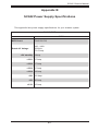
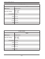
Appendix B: SC842 Power Supply Specications
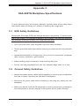
Appendix C: SAS-842TQ Backplane Specications

v
SC842 Chassis Manual
Table of Contents
Chapter 1
Introduction
1-1 Overview ......................................................................................................... 1-1
1-2 Shipping List .................................................................................................... 1-1
Part Numbers .................................................................................................. 1-1
1-3 Chassis Features ............................................................................................ 1-2
CPU Support ................................................................................................... 1-2
Hot-Swappable Hard Drives............................................................................ 1-2
Internal Hard Drives ........................................................................................ 1-2
I/O Expansion slots ......................................................................................... 1-2
Peripheral Drives ............................................................................................. 1-2
Other Features ................................................................................................ 1-2
1-4 Contacting Supermicro .................................................................................... 1-3
Chapter 2 System Safety
2-1 Overview ......................................................................................................... 2-1
2-2 Warnings and Precautions .............................................................................. 2-1
2-3 Preparing for Setup ......................................................................................... 2-1
2-4 Electrical Safety Precautions .......................................................................... 2-2
2-5 General Safety Precautions ............................................................................ 2-3
2-6 System Safety ................................................................................................. 2-3
Chapter 3 Chassis Components
3-1 Overview ......................................................................................................... 3-1
3-2 Components .................................................................................................... 3-1
Hard Drives and Peripheral Drives ................................................................. 3-1
Fans ................................................................................................................ 3-1
Mounting Rails (Optional) ............................................................................... 3-1
Power Supply .................................................................................................. 3-1
3-3 Where to get Replacement Components ........................................................ 3-2
Chapter 4 System Interface
4-1 Overview ......................................................................................................... 4-1
4-2 Control Panel Buttons ..................................................................................... 4-2
4-3 Control Panel LEDs ........................................................................................ 4-2
4-4 Drive Carrier LEDs .......................................................................................... 4-4

SC842 Chassis Manual
vi
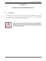
Chapter 5 Chassis Setup and Maintenance
5-1 Overview ......................................................................................................... 5-1
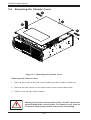
5-2 Removing the Chassis Cover ......................................................................... 5-2
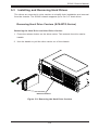
5-3 Installing and Removing Hard Drives ............................................................. 5-3
Removing Hard Drive Carriers (SC842TQ Models) ....................................... 5-3
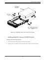
Installing a Drive into the Drive Carrier (SC842TQ Models) .......................... 5-4
Installing Hard Drive Carriers (SC842TQ Models) ......................................... 5-5
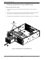
Removing the Hard Drive Cage (SC842i Models) .......................................... 5-6
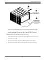
Installing Hard Drives into the Cage (SC842i Models) ................................... 5-7
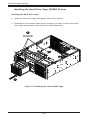
Installing the Hard Drive Cage (SC842i Models) ............................................ 5-8
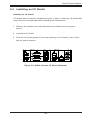
5-4 Installing an I/O Shield .................................................................................... 5-9
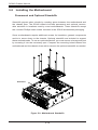
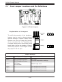
5-5 Installing the Motherboard ............................................................................ 5-10
Permanent and Optional Standoffs ............................................................... 5-10
I/O Shield and Expansion Card Setup .......................................................... 5-12
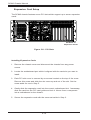
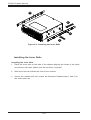
Installing the Rear System Fans ................................................................... 5-13
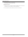
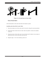
Checking the Server's Air Flow ..................................................................... 5-14
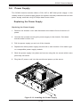
5-6 Power Supply ................................................................................................ 5-15
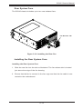
Replacing the Power Supply ......................................................................... 5-15
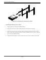
Installing the DVD-ROM or Peripheral Drive ................................................ 5-16
Chapter 6 Rack Installation
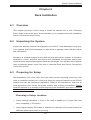
6-1 Overview ......................................................................................................... 6-1
6-2 Unpacking the System .................................................................................... 6-1
6-3 Preparing for Setup ......................................................................................... 6-1
Choosing a Setup Location ............................................................................. 6-1
Rack Precautions ............................................................................................ 6-2
General Server Precautions ............................................................................ 6-2
Rack Mounting Considerations ....................................................................... 6-3
Reduced Airow ......................................................................................... 6-3
Mechanical Loading ................................................................................... 6-3
Circuit Overloading ..................................................................................... 6-3
Reliable Ground ......................................................................................... 6-3
6-4 Rack Mounting ............................................................................................... 6-4
Rack Mounting Overview ................................................................................ 6-4
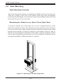
Mounting the Chassis in an Open (Telco) Style Rack .................................... 6-4
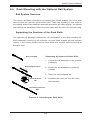
6-5 Rack Mounting with the Optional Rail System .............................................. 6-5
Rail System Overview ..................................................................................... 6-5
Separating the Sections of the Rack Rails ..................................................... 6-5
Installing the Inner Rails ................................................................................. 6-6
Outer Rack Rails ............................................................................................. 6-7

vii
SC842 Chassis Manual
Appendix A SC842 Chassis Cables
Appendix B SC842 Power Supply Specications
Appendix C SAS-842TQ Backplane Specications

SC842 Chassis Manual
viii
Notes

1-1
SC842 Chassis Manual
Legend:
DP/UP: Dual processor/single processor
FF: Full height, full length PCI slots.
Chapter 1
Introduction
1-1 Overview
Supermicro’s SC842 4U chassis features a unique and highly-optimized design.
The chassis is equipped with a high-efciency power supply. High-performance fans
provide ample optimized cooling. Up to ve 3.5" drives provide maximum storage
capacity in a 4U form factor.
1-2 Shipping List
Part Numbers
Please visit the Supermicro Web site for the latest shipping lists and part numbers
for your particular chassis model:
http://www.supermicro.com/products/chassis/4U/?chs=842
SC842 Chassis Series
Model CPU HDD I/O Slots
Power
Supply
SC842TQ-865B DP/UP
5x 3.5" SAS/
SATA drives
7x FF 865W
SC842TQ-665B DP/UP
5x 35" SAS/
SATA drives
7x FF 665W
SC842i-500B DP/UP
5x internal
xed SAS/
SATA drives
7x FF 500W

SC842 Chassis Manual
1-2
1-3 Chassis Features
The SC842 high-performance chassis includes the following features:
CPU Support
The SC842 chassis supports single and dual Intel/AMD processors. Please refer
to the motherboard specications pages on our Web site for updates on supported
processors for this chassis, at www.supermicro.com.
Hot-Swappable Hard Drives
The SC842TQ model chassis features hard drive bays which support up to ve
hot-swappable 3.5" SAS/SATA hard drives. Once set up correctly, hot-swappable
drives can be removed without powering down the server. In addition, these drives
support SES2 (SAS/SATA). 3.5" hard drives are sold separtately.
Internal Hard Drives
The SC842i model chassis support ve internally mounted SAS/SATA hard drives.
In the unlikely event of a hard drive failure, the system must be powered-down and
disconnected from any power source before removing these hard drives.
I/O Expansion slots
Each version of the SC842 chassis includes seven full-height, full-length I/O PCI
slots.
Peripheral Drives
Each SC842 chassis supports one slim DVD drive and up to three 5-1/4" drives.
Other Features
Other onboard features are included to promote system health. These include up to
two rear cooling fans, a convenient power switch, reset button, and LED indicators.

1-3
SC842 Chassis Manual
1-4 Contacting Supermicro
Headquarters
Address: Super Micro Computer, Inc.
980 Rock Ave.
San Jose, CA 95131 U.S.A.
Tel: +1 (408) 503-8000
Fax: +1 (408) 503-8008
Email: [email protected] (General Information)
[email protected] (Technical Support)
Web Site: www.supermicro.com
Europe
Address: Super Micro Computer B.V.
Het Sterrenbeeld 28, 5215 ML
's-Hertogenbosch, The Netherlands
Tel: +31 (0) 73-6400390
Fax: +31 (0) 73-6416525
Email: [email protected] (General Information)
[email protected] (Technical Support)
[email protected] (Customer Support)
Asia-Pacic
Address: Super Micro Computer, Inc.
4F, No. 232-1, Liancheng Rd.
Chung-Ho 235, Taipei County
Taiwan, R.O.C.
Tel: +886-(2) 8226-3990
Fax: +886-(2) 8226-3991
Web Site: www.supermicro.com.tw
Technical Support:
Email: [email protected]
Tel: +886-(2) 8226-5990

SC842 Chassis Manual
1-4
Notes

2-1
SC842 Chassis Manual
Chapter 2
System Safety
2-1 Overview
This chapter provides a quick setup checklist to get your chassis up and running.
Following the steps in order given should enable you to have your chassis set up
and operational within a minimal amount of time. These instructions assume that you
are an experienced technician, familiar with common concepts and terminology.
2-2 Warnings and Precautions
You should inspect the box the chassis was shipped in and note if it was damaged
in any way. If the chassis itself shows damage, le a damage claim with the carrier
who delivered your system.
Decide on a suitable location for the rack unit that will hold the chassis. It should be
situated in a clean, dust-free area that is well ventilated. Avoid areas where heat,
electrical noise and electromagnetic elds are generated.
Place the chassis near a grounded power outlets. The SC842 chassis includes a
power supply which requires a grounded outlet.
2-3 Preparing for Setup
The SC842 chassis includes mounting screws you will need to install the system
into an open (two-post) rack. Optional mounting rails are available for installation
of the chassis into a four-post rack. Part numbers for these mounting rails may
be found on the Supermicro Web site at http://www.supermicro.com/products/
chassis/4U/?chs=842. Please read this manual in its entirety before beginning the
installation procedure.

2-2
SC842 Chassis Manual
2-4 Electrical Safety Precautions
Basic electrical safety precautions should be followed to protect yourself from harm
and the SC842 from damage:
•Be aware of the locations of the power on/off switch on the chassis as well
as the room’s emergency power-off switch, disconnection switch or electrical
outlet. If an electrical accident occurs, you can then quickly remove power from
the system.
•Do not work alone when working with high-voltage components.
•Power should always be disconnected from the system when removing or in-
stalling main system components, such as the serverboard, memory modules
and the DVD-ROM (not necessary for hot-swappable drives). When discon-
necting power, you should rst power-down the system with the operating
system and then unplug the power cords from all the power supply modules
in the system.
•When working around exposed electrical circuits, another person who is fa-
miliar with the power-off controls should be nearby to switch off the power, if
necessary.
•Use only one hand when working with powered-on electrical equipment. This
is to avoid making a complete circuit, which will cause electrical shock. Use
extreme caution when using metal tools, which can easily damage any electrical
components or circuit boards they come into contact with.
•Do not use mats designed to decrease electrostatic discharge as protection from
electrical shock. Instead, use rubber mats that have been specically designed
as electrical insulators.
•The power supply power cord must include a grounding plug and must be
plugged into grounded electrical outlets.
•Serverboard battery: CAUTION - There is a danger of explosion if the onboard
battery is installed upside down, which will reverse its polarities. This battery
must be replaced only with the same or an equivalent type recommended by
the manufacturer. Dispose of used batteries according to the manufacturer’s
instructions.

2-3
SC842 Chassis Manual
•Please handle used batteries carefully. Do not damage the battery in any way;
a damaged battery may release hazardous materials into the environment. Do
not discard a used battery in the garbage or a public landll. Please comply
with the regulations set up by your local hazardous waste management agency
to dispose of your used battery properly.
•DVD-ROM laser: CAUTION - This server may have come equipped with an
optional DVD-ROM drive. To prevent direct exposure to the laser beam and
hazardous radiation exposure, do not open the enclosure or use the unit in any
unconventional way.
2-5 General Safety Precautions
•Keep the area around the chassis clean and free of clutter.
•Place the chassis top cover and any system components that have been re-
moved away from the system or on a table so that they won’t accidentally be
stepped on.
•While working on the system, do not wear loose clothing such as neckties and
unbuttoned shirt sleeves, which can come into contact with electrical circuits or
be pulled into a cooling fan.
•Remove any jewelry or metal objects from your body, which are excellent metal
conductors that can create short circuits and harm you if they come into contact
with printed circuit boards or areas where power is present.
•After accessing the inside of the system, close the system back up and secure
it to the rack unit with the retention screws after ensuring that all connections
have been made.
2-6 System Safety
Electrostatic discharge (ESD) is generated by two objects with different electrical
charges coming into contact with each other. An electrical discharge is created to
neutralize this difference, which can damage electronic components and printed
circuit boards. The following measures are generally sufcient to neutralize this
difference before contact is made to protect your equipment from ESD:
•Do not use mats designed to decrease electrostatic discharge as protection from
electrical shock. Instead, use rubber mats that have been specically designed
as electrical insulators.

2-4
SC842 Chassis Manual
•Use a grounded wrist strap designed to prevent electrostatic discharge.
•Keep all components and printed circuit boards (PCBs) in their antistatic bags
until ready for use.
•Touch a grounded metal object before removing any board from its antistatic
bag.
•Do not let components or PCBs come into contact with your clothing, which may
retain a charge even if you are wearing a wrist strap.
•Handle a board by its edges only; do not touch its components, peripheral chips,
memory modules or contacts.
•When handling chips or modules, avoid touching their pins.
•Put the serverboard and peripherals back into their antistatic bags when not
in use.
•For grounding purposes, make sure your computer chassis provides excellent
conductivity between the power supply, the case, the mounting fasteners and
the serverboard.

3-1
SC842 Chassis Manual
Chapter 3
Chassis Components
3-1 Overview
This chapter describes the most common components included with your chassis.
Some components listed may not be included or compatible with your particular
chassis model. For more information, see the installation instructions detailed later
in this manual.
3-2 Components
Hard Drives and Peripheral Drives
The SC842 chassis supports up to ve hot-swappable 3.5" hard drives (SC842TQ
series) or up to ve internal hard drives (SC842i series), and one peripheral drive
bay which can be used to install one optional slim DVD-ROM drive and up to three
5-1/4" hard drives. For the latest shipping list, visit our Web site at: http://www.
supermicro.com.
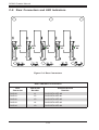
Fans
The SC842 chassis supports one 9 cm front cooling fan and two 8 cm rear exhaust
fans. System fans for the SC842 chassis are powered from the serverboard. These
fans are powered by 4-pin connectors.
Mounting Rails (Optional)
The SC842 can be placed on a four-post rack for secure storage and use. To set
up your rack with the optional mounting rail, follow the step-by-step instructions
included in this manual.
Power Supply
Each SC842 chassis model includes a high-efciency power supply rated at 500,
665 or 865 Watts. In the unlikely event of a power supply failure, replacement is
easily accomplished without tools.

3-2
SC842 Chassis Manual
3-3 Where to get Replacement Components
Although not frequently, you may need replacement parts for your system. To
ensure the highest level of professional service and technical support, we strongly
recommend purchasing exclusively from our Supermicro Authorized Distributors/
System Integrators/Resellers. A list of Supermicro Authorized Distributors/System
Integrators/Reseller can be found at: http://www.supermicro.com. Click the Where
to Buy link.

4-1
SC842 Chassis Manual
Chapter 4
System Interface
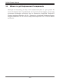
4-1 Overview
There are several LEDs on the control panel as well as others on the drive carriers
to keep you constantly informed of the overall status of the system as well as the
activity and health of specic components. SC842 models have two buttons on the
chassis control panel: a reset button and an on/off switch. This chapter explains
the meanings of all LED indicators and the appropriate response you may need
to take.
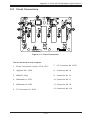
Figure 4-1: SC842 Front Panel

4-2
SC842 Chassis Manual
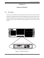
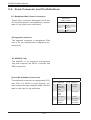
4-2 Control Panel Buttons
There are two push-buttons located on the front of the chassis. These are (in order
from left to right), a reset button and a power on/off button.
•Reset: The reset button is used to reboot the system.
•Power: The main power switch is used to activate or remove power from the
power supply to the server system. Turning off system power with this button
removes the main power but keeps standby power supplied to the system.
Therefore, you must unplug system before servicing.
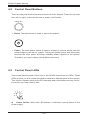
4-3 Control Panel LEDs
The control panel located on the front of the SC842 chassis has six LEDs. These
LEDs provide you with critical information related to different parts of the system.
This section explains what each LED indicates when illuminated and any correc-
tive action you may need to take.
Power Failure: When this LED ashes, it indicates a power failure in the
power supply.
!
Page is loading ...
Page is loading ...
Page is loading ...
Page is loading ...
Page is loading ...
Page is loading ...
Page is loading ...
Page is loading ...
Page is loading ...
Page is loading ...
Page is loading ...
Page is loading ...
Page is loading ...
Page is loading ...
Page is loading ...
Page is loading ...
Page is loading ...
Page is loading ...
Page is loading ...
Page is loading ...
Page is loading ...
Page is loading ...
Page is loading ...
Page is loading ...
Page is loading ...
Page is loading ...
Page is loading ...
Page is loading ...
Page is loading ...
Page is loading ...
Page is loading ...
Page is loading ...
Page is loading ...
Page is loading ...
Page is loading ...
Page is loading ...
Page is loading ...
Page is loading ...
Page is loading ...
Page is loading ...
-
 1
1
-
 2
2
-
 3
3
-
 4
4
-
 5
5
-
 6
6
-
 7
7
-
 8
8
-
 9
9
-
 10
10
-
 11
11
-
 12
12
-
 13
13
-
 14
14
-
 15
15
-
 16
16
-
 17
17
-
 18
18
-
 19
19
-
 20
20
-
 21
21
-
 22
22
-
 23
23
-
 24
24
-
 25
25
-
 26
26
-
 27
27
-
 28
28
-
 29
29
-
 30
30
-
 31
31
-
 32
32
-
 33
33
-
 34
34
-
 35
35
-
 36
36
-
 37
37
-
 38
38
-
 39
39
-
 40
40
-
 41
41
-
 42
42
-
 43
43
-
 44
44
-
 45
45
-
 46
46
-
 47
47
-
 48
48
-
 49
49
-
 50
50
-
 51
51
-
 52
52
-
 53
53
-
 54
54
-
 55
55
-
 56
56
-
 57
57
-
 58
58
-
 59
59
-
 60
60


Supermicro SuperChassis 842TQ-665B User manual
- Category
- Computer cases
- Type
- User manual
- This manual is also suitable for
Ask a question and I''ll find the answer in the document
Finding information in a document is now easier with AI
Related papers
-
Supermicro MCP-290-00053-0N Datasheet
-
-
Supermicro CSE-842I-500B User manual
-
-
-
-
-
Supermicro Power Distribution Unit User manual
-
-
Other documents
-
Kyosho MZW116�@Setting Weight User manual
-
Acer SO.CAG05.C07 Datasheet
-
In Win IW-RA100 + 300W User manual
-
Intel SC450NX User manual
-
Sophos ES1100 Setup Manual
-
Fantec MR-SA1042 User manual
-
Dell W-ClearPass Hardware Appliances Installation guide
-
 Supero SAS-825TQ User manual
-
Contec FA-UNIT-F14BE Owner's manual
-
 Supero M35TQ User manual

