— 1 — — 2 — — 3 —
NPort 5200 Series
Quick Installation Guide
Sixth Edition, June 2008
1. Overview
The NPort 5200 Series of compact palm-sized device servers are used to
control RS-232 (NPort 5210/5230/5210-T/5230-T) or RS-422/485 (NPort
5230/5232/5232I/5230-T/5232-T/5232I-T) serial devices over a
TCP/IP-based Ethernet.
Note:
“-T” indicates an extended temperature model.
2. Package Checklist
Before installing NPort 5200, verify that the package contains the
following items:
y 1 NPort 5200 2-port Serial Device Server
y Documentation & Software CD
y NPort 5200 Series Quick Installation Guide
Optional Accessories
y DK-35A DIN-Rail Mounting Kit (35 mm)
y CBL-RJ45M9-150 RJ45 (8-pin) to DB9 (M) cable, 150 cm
y CBL-RJ45F9-150 RJ45 (8-pin) to DB9 (F) cable, 150 cm
y CBL-RJ45M25-150 RJ45 (8-pin) to DB25 (M) cable, 150 cm
y CBL-RJ45F25-150 RJ45 (8-pin) to DB25 (F) cable, 150 cm
y DIN-Rail Power Supply and Adapter
Notify your sales representative if any of the above items is missing or
damaged.
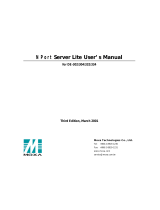
3. Hardware Introduction
The NPort 5200 series of device servers are used to control
RS-232/422/485 devices. NPort 5210/5210-T has two 8-pin RJ45 ports,
both for the RS-232 interface. NPort 5230/5230-T has one 10-pin
terminal block, with 5 pins used for one RS-232 port, and 5 pins used for
one RS-422/485 port. NPort 5232/5232I/5232-T/5232I-T have one 10-pin
terminal block, with 5 pins used for one RS-422/485 port, and 5 pins used
for another RS-422/485 port.
NPort 5210/5210-T NPort 5230/5230-T
10/100M
Ethernet
V+
V-
P1 RS-232
P2 RS-232
Ready
Link
P1
P2
Industrial RS-232 Device Server
5210
RESET
12-30V
RJ45 10/100M
Ethernet port
Reset
button
Terminal Block
Power input
DIN-Rail
screw hole
Wallmount
screw hole
5210
Industrial RS-232/422/485 Device Server
5230
10/100M
Ethernet
V+
V-
Ready
Link
P1
P2
P1 RS-232
Tx
Rx
RTS
CTS
GND
T+
T-
R+/D+
R-/D-
GND
P2 RS-485/422
RESET
12-30V
RS-232 & RS-422/485
Terminal Block
8-pin RJ45
serial ports
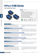
NPort 5232/5232-T NPort 5232I/5232I-T
RJ45 10/100M
Ethernet port
Reset
button
Terminal Block
Power input
DIN-Rail
screw hole
Wallmount
screw hole
RS-422/485 Terminal Block RS-422/485 Terminal Block
5210
Industrial RS-422/485 Device Server
5232I
10/100M
Ethernet
V+
V-
Ready
Link
P1
P2
P1 RS-232
Tx
Rx
RTS
CTS
GND
T+
T-
R+/D+
R-/D-
GND
P2 RS-485/422
RESET
12-30V
5210
Industrial RS-422/485 Device Server
5232
10/100M
Ethernet
V+
V-
Ready
Link
P1
P2
P1 RS-232
Tx
Rx
RTS
CTS
GND
T+
T-
R+/D+
R-/D-
GND
P2 RS-485/422
RESET
12-30V
Reset Button—Press the Reset button continuously for 5 sec to load
factory defaults: Use a pointed object, such as a straightened paper clip or
toothpick, to press the reset button. This will cause the Ready LED to
blink on and off. The factory defaults will be loaded once the Ready LED
stops blinking (after about 5 seconds). At this point, you should release
the reset button.
NPort 5200 LED Indicators (top panel)
LED
Name
LED
Color
LED Function
red
Steady on: Power is on and NPort 5200 is
booting up.
Blinking: Indicates an IP conflict, or DHCP or
BOOTP server did not respond
properly.
green
Steady on: Power is on and NPort 5200 is
functioning normally.
Blinking: The device server has been located
by Administrator’s Location function
Ready
off Power is off, or power error condition exists.
orange
10 Mbps Ethernet connection.
green
100 Mbps Ethernet connection.
Ethernet
off Ethernet cable is disconnected, or has a short.
orange
Serial port is receiving data.
green
Serial port is transmitting data.
P1, P2
off
No data is being transmitted or received through
the serial port.
4. Hardware Installation Procedure
STEP 1: After removing NPort 5200 from the box, the first thing you
should do is connect the power adaptor. Connect the 12-30 VDC power
line with NPort 5200’s terminal block, or connect the DIN-Rail power
supply with NPort 5200’s terminal block.
STEP 2: Connect NPort 5200 to a network. Use a standard
straight-through Ethernet cable to connect to a Hub or Switch. When
setting up or testing NPort 5200, you might find it convenient to connect
directly to your computer’s Ethernet port. In this case, use a cross-over
Ethernet cable.
STEP 3: Connect NPort 5200’s serial port to a serial device.
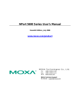
STEP 4: Placement Options
In addition to placing
NPort 5200 on a
desktop or other
horizontal surface, you
may also make use of
the DIN-Rail or Wall
Mount options, as
illustrated here.
Wall Mount
10/100M
Ethernet
V+
V-
P1 RS-232
P2 RS-232
Ready
Link
P1
P2
Industrial RS-232 Device Server
5210
RESET
12-30V
5210
DIN-Rail
P/N: 1802002010400