Page is loading ...
Palm Beach
48 in Ceiling Fan
Owner’s Manual
Palm Beach
Ventilador de Techo de 1,22
m
Manual del Propietario
265 316
150 mm
213 mm
The spot color is for reference proof only, please follow
pantone guide for actual color when printing.
This line is for die-cut position only
DO NOT PRINT IT!!!
Black Magenta Yellow Black PMS 465C PMS 5425C PMS 632C Die
Total Colors
1C
Coating
Varnish
ADDITIONAL INFORMATION
V0.0
10-01-20
V0.0
17 Apr 09
V0.0
17 Apr 09
V0.0
17 Apr 09
V0.0
17 Apr 09
V0.0
17 Apr 09
V0.0
17 Apr 09
V0.0
17 Apr 09
V0.0
17 Apr 09
V0.0
17 Apr 09
V0.0
17 Apr 09
V0.0
17 Apr 09
V0.0
17 Apr 09
V0.0
17 Apr 09
V0.0
17 Apr 09
1. UPC at 100% and without truncated.
2. The smallest fonts size is 6 points in the artwork.
File Name:
Artwork Version:
Customer:
Buyer:
Sold In Country:
Item Number:
Catergory:
MVendor:
Printing Type:
Translation Agency:
Size:
Blank Size:
Artist:
C.S.:
Date:
HD_014835A_265316_MC
V0.0
Home Depot
N/A
US
TBA
Hampton Bay (Ceiling Fan)
KOF CLZ
Offest
TBA
213(L) x 150(W) mm
213(L) x 150(W) mm
Mary
Chris Que
10-01-20

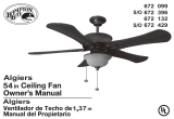
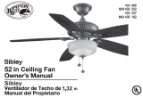
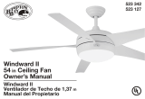
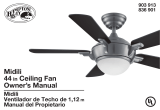
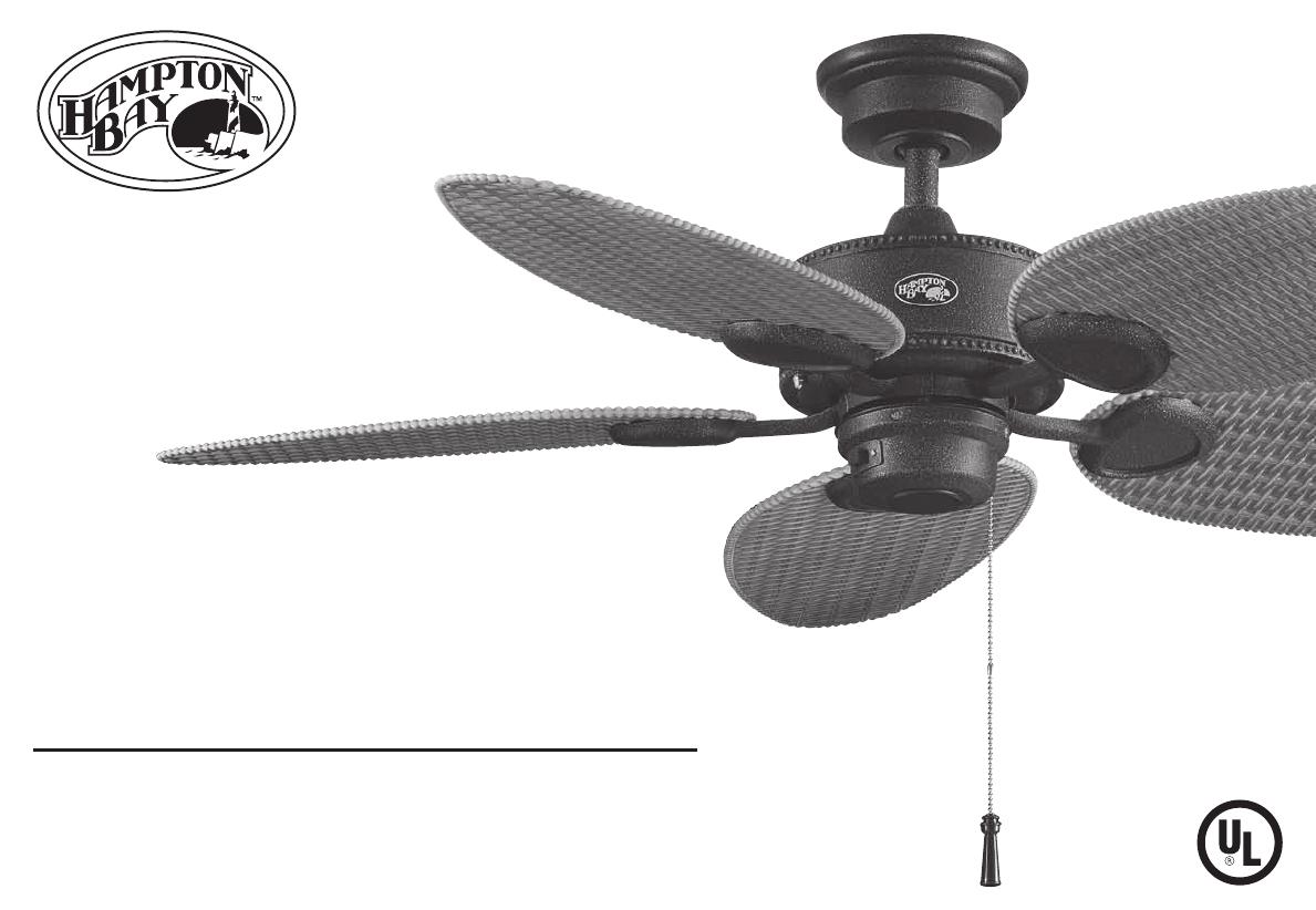
48” Palm Beach
Ceiling Fan by Hampton Bay
Accu-Arm™ for Accurate
and Easy Installation
Indoor/Outdoor Use
3-Speed Reverse Function for
Year-Round Comfort and Savings
Tri-Mount Installation
QUESTIONS, PROBLEMS, MISSING PARTS:
Before returning to your local Home Depot, please call our
Customer Service Team at 1-877-527-0313 or visit www.homedepot.com.
Please reference your SKU (265 316 gilded iron, 460 470 textured white)
or UPC (082392 725600 gilded iron, 082392 725662 textured white).
Thank you for purchasing this Hampton Bay ceiling
fan. This product has been manufactured with the
highest standards of safety and quality. The nish
of this fan is weather resistant, but over time will
naturally weather and fade.
Safety Rules .................................. 1
Unpacking Your Fan .................... 2
Installing Your Fan ...................... 3
Operating Your Fan ..................... 9
Care of Your Fan .......................... 10
Troubleshooting ............................ 10
Specications ................................ 11
Warranty Information ................. 12
Table of Contents
UL Model No. 48-PB
Safety Rules .................................. 1
Unpacking Your Fan .................... 2
Installing Your Fan ...................... 3
Operating Your Fan ..................... 9
Care of Your Fan .......................... 10
Troubleshooting ............................ 10
Specications ................................ 11
Warranty Information ................. 12
1. To reduce the risk of electric shock, insure electricity
has been turned off at the circuit breaker or fuse box
before beginning.
2. All wiring must be in accordance with the National
Electrical Code ANSI/NFPA 70-1999 and local electrical
codes. Electrical installation should be performed by a
qualied licensed electrician.
3. WARNING: To reduce the risk of re or electric shock, do
not use this fan with any solid-state speed control device.
4. CAUTION: To reduce the risk of personal injury, use only
the screws provided with the outlet box.
5. The outlet box and support structure must be securely
mounted and capable of reliably supporting a minimum of
35 pounds. Use only UL Listed outlet boxes marked “FOR
FAN SUPPORT.”
6. The fan must be mounted with a minimum of 7 feet
clearance from the trailing edge of the blades to the oor.
7. Do not operate reversing switch while fan blades are in mo-
tion. Fan must be turned off and blades stopped before re-
versing blade direction.
8. Avoid placing objects in path of the blades.
9. To avoid personal injury or damage to the fan and other items,
be cautious when working around or cleaning the fan.
10. Do not use water or detergents when cleaning the fan or fan
blades. A dry dust cloth or lightly dampened cloth will be
suitable for most cleaning.
11. After making electrical connections, spliced conductors
should be turned upward and pushed carefully up into
outlet box. The wires should be spread apart with the
grounded conductor and the equipment-grounding
conductor on one side of the outlet box.
12. Electrical diagrams are for reference only. Light kits that
are not packed with the fan must be UL listed and marked
suitable for use with the model fan you are installing. If us-
ing this fan in a wet or damp environment, light kit must be
marked “Suitable for Use in Wet Location”. Switches must
be UL General Use Switches. Refer to the instructions pack-
aged with the light kits and switches for proper assembly.
13. SUITABLE FOR USE IN WET LOCATIONS when
installed in a GFCI protected branch circuit.
14. All set screws must be checked and retightened where
necessary before installation.
Safety Rules 1.
READ AND SAVE THESE INSTRUCTIONS
TO REDUCE THE RISK OF FIRE, ELECTRIC SHOCK OR PERSONAL
INJURY, MOUNT TO OUTLET BOX MARKED ACCEPTABLE FOR FAN
SUPPORT AND USE SCREWS PROVIDED WITH THE OUTLET BOX.
PLEASE REMOVE RUBBER MOTOR STOPS ON THE BOTTOM OF THE
FAN BEFORE INSTALLING BLADES OR TESTING THE MOTOR.
TO REDUCE THE RISK OF PERSONAL INJURY, DO NOT BEND THE
BLADE BRACKETS (ALSO REFERRED TO AS “FLANGES”) DURING
ASSEMBLY OR AFTER INSTALLATION. DO NOT INSERT OBJECTS IN
THE PATH OF THE BLADES.

a. Blade attachment hardware
(15 screws)
b. Electrical Hardware
(3 plastic wire connectors, 1 hanger pin, 1
locking pin, balancing kit)
c. Close-to-Ceiling mount hardware
(1 rubber gasket)
d. Miscellaneous Parts
(1 pull chain)
7. Blades (5)
8. Blade Bracket (Flange) Set (5)
with blade bracket screws pre-installed
1. Slide-On Mounting Plate (inside canopy)
2. Ball/Downrod Assembly
3. Canopy with Canopy Ring attached
4. Fan Motor Assembly
5. Switch Cup
6. Decorative Motor Collar Cover
2. Unpacking Your Fan
IMPORTANT: THIS PRODUCT AND/OR COMPONENTS ARE COV-
ERED BY ONE OR MORE OF THE FOLLOWING U.S. PATENTS:
5,947,436; 5,988,580; 6,010,110; 6,046,416, 6,210,117 AND OTHER
PATENTS PENDING.
Unpack your fan and check the contents. You should have the following items:

Installing Your Fan 3.
Tools Required
Phillips screw driver, straight slot screw
driver, adjustable wrench, step ladder, and
wire cutters.
Mounting Options
If there isn’t an existing outlet box, then read
the following instructions. Disconnect the
power by removing fuses or turning off
circuit breakers.
Secure the outlet box directly to the building
structure. Use appropriate fasteners and
building materials. The outlet box and its
support must be able to fully support the
moving weight of the fan (at least 35 lbs.)
Do not use plastic outlet boxes.
Figures 1, 2, and 3 are examples of different
ways to mount the outlet box.
Note: You may need a longer downrod to
maintain proper blade clearance when install-
ing on a steep, sloped ceiling. The maximum
angle allowable is 30˚. If the canopy touches
downrod, remove the decorative canopy
bottom cover and turn the canopy 180˚ before
attaching the canopy to the mounting plate.
To hang your fan where there is an existing
xture but no ceiling joist, you may need an
installation hanger bar as shown in Figure 4
(available at your Hampton Bay retailer).
Figure 1
Figure 2
Figure 4
Figure 3
TO REDUCE THE RISK OF FIRE, ELECTRIC
SHOCK OR PERSONAL INJURY, MOUNT FAN
ONLY TO AN OUTLET BOX MARKED ACCEPT-
ABLE FOR FAN SUPPORT AND USE THE
MOUNTING SCREWS PROVIDED WITH THE OUT-
LET BOX. OUTLET BOXES COMMONLY USED
FOR THE SUPPORT OF LIGHTING FIXTURES
MAY NOT BE ACCEPTABLE FOR FAN SUPPORT
AND MAY NEED TO BE REPLACED. CONSULT A
LICENSED ELECTRICIAN IF IN DOUBT.
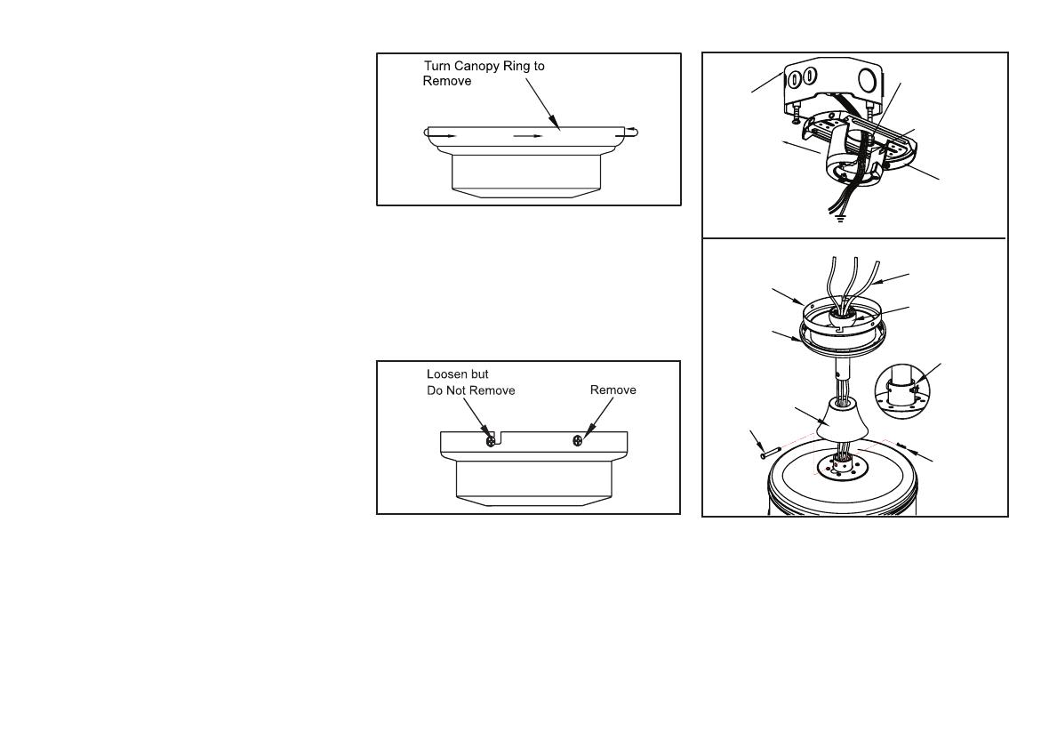
2. Remove the mounting plate from the
canopy by loosening the four screws on
the top of the canopy. Remove the two
non-slotted screws and loosen the slotted
screws. This will enable you to remove the
mounting plate (Figure 6).
4.
Hanging the Fan
REMEMBER to turn off the pow-
er. Follow the steps below to hang your
fan properly.
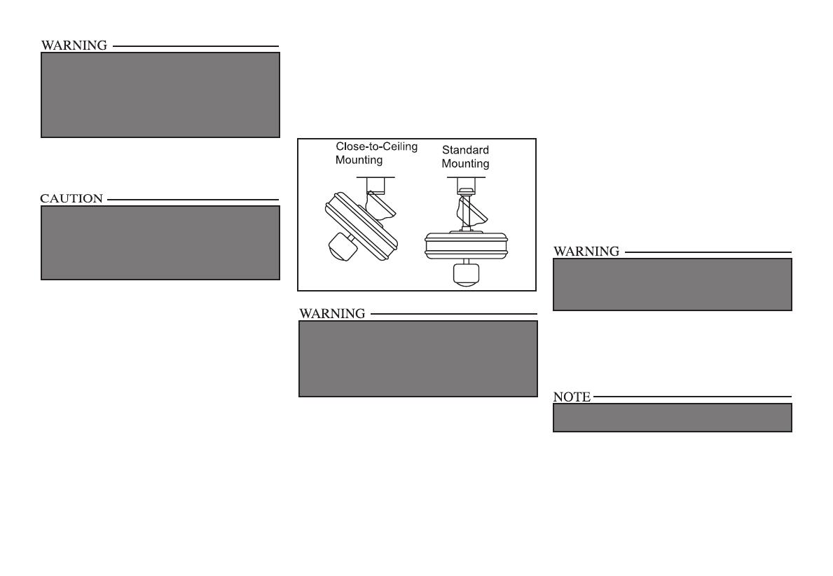
NOTE: This ceiling fan is supplied with two
types of hanging assemblies; the standard
ceiling installation using the downrod with
ball and socket mounting, and the “close-to-
ceiling” mounting. The “close-to-ceiling”
mounting is recommended in rooms with
less than 8-foot ceilings or in areas where
additional space is desired from the oor
to the fan blades. When using standard
downrod installation, the distance from the
ceiling to the bottom of the fan blades will be
approximately 12 inches. The “close-to-ceiling”
installation reduces the distance from the
ceiling to the bottom of the fan blades to
approximately 9 inches.
Once you have decided which ceiling
installation you will use, proceed with the
following instructions. Where necessary,
each section of the instructions will note the
different procedures to follow for the two
types of installation.
Standard Ceiling Mounting
1. Remove the canopy ring from the canopy
by turning the ring to the right until it
unlocks (Figure 5).
Figure 5
Figure 6
Figure 7
3. Route the wires exiting the top of the
fan motor through the decorative motor
collar cover then the canopy ring. Make sure
the slot openings are on top. Route the wires
through the canopy and then through the
ball/downrod assembly (Figure 7).
Pin in
Locked
Position
Locking Pin
Hanger Pin
Motor Collar Cover
Canopy Ring
Canopy
Downrod/Ball
Assembly
Motor Wires
Hook
Ceiling
Mounting
Plate
Mounting
Screws
(Supplied With
Outlet Box)
UL Listed
Outlet Box
Slide Mounting
Plate Over
Screw Heads
120V Wires

“Close-to-Ceiling” Mounting
1. Remove the canopy ring from the canopy
by turning the ring to the right until it
unlocks (Figure 5).
2. Remove the mounting plate from the cano-
py by loosening the four screws on the top
of the canopy. Remove the two non-slotted
screws and loosen the slotted screws. This
will enable you to remove the mounting
plate (Figure 6).
3. Remove the decorative canopy bottom cov-
er from the canopy by depressing the three
studs (Figure 9).
4. Remove three of the six screws and lock-
washers (every other one) securing the re-
inforcing plate to the top of the fan motor
housing (Figure 10).
5. Place the rubber gasket over the remaining
three screws, route the wires exiting the top
of the fan motor through the ceiling cano-
py over the collar at the top of the motor
(Figure 11).
5.
4. Loosen, but do not remove, the set
screw on the collar on the top of the
motor housing.
5. Align the holes at the bottom of the
downrod with the holes in the collar
on top of the motor housing (Figure 7).
Carefully insert the hanger pin through
the holes in the collar and downrod. Be
careful not to jam the hanger pin against
the wiring inside the downrod. Insert the
locking pin through the hole near the
end of the hanger pin until it snaps into its
locked position, as noted in the circle inset
of Figure 7.
6. Re-tighten the set screws on the collar on top
of the motor housing (Figure 8).
7. Proceed to “Installing the Fan” section.
FAILURE TO PROPERLY INSTALL SET SCREWS
IN STEP 7 COULD RESULT IN FAN LOOSENING
AND POSSIBLY FALLING.
FAILURE TO PROPERLY INSTALL THE LOCK-
ING PIN AS NOTED IN STEP 5 COULD RESULT
IN FAN LOOSENING AND POSSIBLY FALLING.
Figure 8
Figure 9
Figure 10
Figure 11
6. Align the mounting holes with the holes
in the motor and fasten, using the three
screws and lock-washers removed in step 4
(Figure 11).
7. Tighten the mounting screws securely.
6.
WHEN USING THE STANDARD BALL/DOWN-
ROD MOUNTING, THE TAB IN THE RING AT THE
BOTTOM OF THE MOUNTING BRACKET MUST
REST IN THE GROOVE OF THE HANGER BALL.
FAILURE TO PROPERLY SEAT THE TAB IN THE
GROOVE COULD CAUSE DAMAGE TO WIRING.
Installing Fan to
the Outlet Box
WHEN MOUNTING THE FAN ON A SLOPED
CEILING, THE STANDARD BALL/DOWNROD
MOUNTING METHOD MUST BE USED. MAKE
SURE THE MOUNTING BRACKET SLOTS ARE
ON THE LOWER SIDE BY SLIDING THE MOUNT-
ING BRACKET FROM THE TOP DOWN.
1. Pass the 120-volt supply wires through the
center hole in the ceiling mounting bracket
as shown in Figure 7.
2. Install the ceiling mounting plate on the out-
let box by sliding the mounting bracket over
the two screws provided with the outlet box.
When using close-to-ceiling mounting, it is
important that the mounting plate be level.
If necessary, use leveling washers (not in-
cluded) between the mounting bracket and
the outlet box. Note that the at side of the
mounting bracket is toward the outlet box
(Figure 7).
3. Securely tighten the two mounting screws.
4. Carefully lift the assembly up to the ceil-
ing mounting plate. If using Close-to-
Ceiling mounting, hang the fan on the
hook provided by utilizing one of the
holes at the outer rim of the ceiling canopy
(Figure 12). If using standard mounting, seat
the hanger ball in the mounting plate socket.
Make sure the tab on the mounting bracket
socket is properly seated in the groove in the
hanger ball (Figure 12).
Figure 12
THE HOOK AS SHOWN IN FIGURE 12 IS ONLY
TO BALANCE FAN WHILE ATTACHING WIRING.
FAILURE TO HANG AS SHOWN IN FIGURE 12
MAY RESULT IN HOOK BREAKING, CAUSING
THE FAN TO FALL. HOOK MUST PASS FROM
INSIDE TO OUTSIDE OF CANOPY.
Making the Electrical
Connections
REMEMBER to disconnect the power. If
you feel you do not have enough electrical
wiring knowledge or experience, have your fan
installed by a licensed electrician.
Follow the steps below to connect the fan
to your household wiring. Use the wire
connecting nuts supplied with your fan. Se-
cure the connectors with electrical tape.
Make sure there are no loose strands or
connections.
1. Connect the two green fan ground wires lo-
cated on the downrod and mounting plate
to the household ground wire. When using
Close-to-Ceiling mounting, there is only one
green ground wire from the ceiling mount-
ing plate since the ball/downrod assembly is
not used.
2. IF USING OPTIONAL LIGHT KIT, Con-
nect the fan light supply (blue) wire and the
fan supply (black) wire to the black house-
hold supply wire as shown in gure 13.
3. Connect the neutral fan (white) wire to the
white neutral household wire.
4. After connecting the wires, spread them
apart so that the green and white wires are
on side of the outlet box and the black wire
is on the other side.
ELECTRICAL DIAGRAMS ARE FOR REFERENCE
ONLY. OPTIONAL USE OF ANY LIGHT KIT SHALL
BE UL LISTED AND MARKED SUITABLE FOR
USE WITH THIS FAN.
USE ONLY WITH LIGHT KITS MARKED “SUIT-
ABLE FOR USE IN WET LOCATION”.

7.
EACH WIRE NUT (WIRE CONNECTOR) SUP-
PLIED WITH THIS FAN IS DESIGNED TO ACCEPT
UP TO ONE 12 GAUGE HOUSE WIRE AND TWO
WIRES FROM THE FAN. IF YOU HAVE LARGER
THAN 12 GAUGE HOUSE WIRING OR MORE
THAN ONE HOUSE WIRE TO CONNECT TO THE
FAN WIRING, CONSULT AN ELECTRICIAN FOR
THE PROPER SIZE WIRE NUTS TO USE.
TO REDUCE THE RISK OF FIRE OR ELECTRIC
SHOCK, DO NOT USE A WALL MOUNTED SOLID
STATE SPEED CONTROL WITH THIS FAN. IT
WILL PERMANENTLY DAMAGE THE ELEC-
TRONIC CIRCUITRY.
Figure 13
5. Turn the wire connecting nuts upward and
push the wiring into the outlet box.
Finishing the Fan
Installation
STANDARD CEILING MOUNTING
1. Align the locking slots of the ceiling canopy
with the two screws in the mounting bracket.
Push up to engage the slots and turn clock-
wise to lock in place. Immediately tighten
the two mounting screws rmly.
2. Install the remaining two mounting
screws into the holes in the canopy and
tighten rmly.
3. Install the decorative canopy ring by align-
ing the ring’s slots with the screws in the
canopy. Rotate the ring clockwise to lock in
place.
4. You may now proceed to attaching the
fan blades.
WHEN USING THE STANDARD BALL/DOWNROD
MOUNTING, THE TAB IN THE RING AT THE BOT-
TOM OF THE MOUNTING PLATE MUST REST IN
THE GROOVE OF THE HANGER BALL. FAILURE
TO PROPERLY SEAT THE TAB IN THE GROOVE
COULD CAUSE DAMAGE TO WIRING.
CLOSE-TO-CEILING MOUNTING
1. Carefully unhook the fan from the mount-
ing bracket and align the locking slots of
the ceiling canopy with the two screws in
the mounting plate. Push up to engage the
slots and turn clockwise to lock in place. Im-
mediately tighten the two mounting screws
rmly.
2. Install the remaining two mounting screws
into the holes in the canopy and tighten
rmly.
3. Install the decorative canopy ring by align-
ing the ring’s slots with the screws in the
canopy. Rotate the ring clockwise to lock in
place.
4. You may now proceed to attaching the fan
blades.
8.
LOCKING SLOTS OF CEILING CANOPY ARE
PROVIDED ONLY AS AN AID TO MOUNTING.
DO NOT LEAVE FAN ASSEMBLY UNATTENDED
UNTIL ALL FOUR CANOPY SCREWS ARE EN-
GAGED AND FIRMLY TIGHTENED.
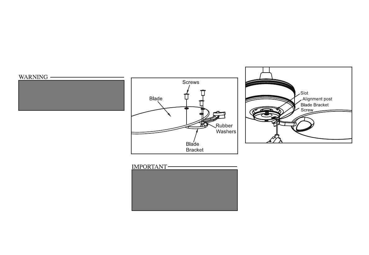
Attaching the
Fan Blades
1. Attach blade to blade bracket using the
screws as shown in gure 14. Please note that
the rubber washers are pre-attached to the
blade bracket. Start a screw into the bracket.
Repeat for the two remaining screws
2. Tighten each screw securely.
Figure 14
Figure 15
REMOVE RUBBER STOPPERS ON THE BLACK
PLATE BELOW THE MOTOR TO ATTACH BLADE
ASSEMBLY TO MOTOR. REPLACE RUBBER
STOPPERS TO PREVENT WATER FROM ENTER-
ING SWITCH HOUSING AND TO REDUCE RISK
OF FIRE, ELECTRIC SHOCK OR OTHER PER-
SONAL INJURY.
3. Fasten the blade assembly to the motor by
inserting the alignment post into the slot on
the bottom of the motor and tightening the
blade bracket screws. Please note that the
blade bracket screws are pre-installed into
the blade bracket (Figure 15).
4. Repeat steps 1-3 for the remaining blades.
Attaching the
Switch Housing
1. Connect the adaptor plug exiting the bottom
of the motor with the plug from the switch
housing.
2. Mount the switch housing to the black plate
below the motor by aligning the four screw
holes and securing with the four tapered
screws provided.
Operating Your Fan 9.
Figure 16
Figure 17
Figure 18
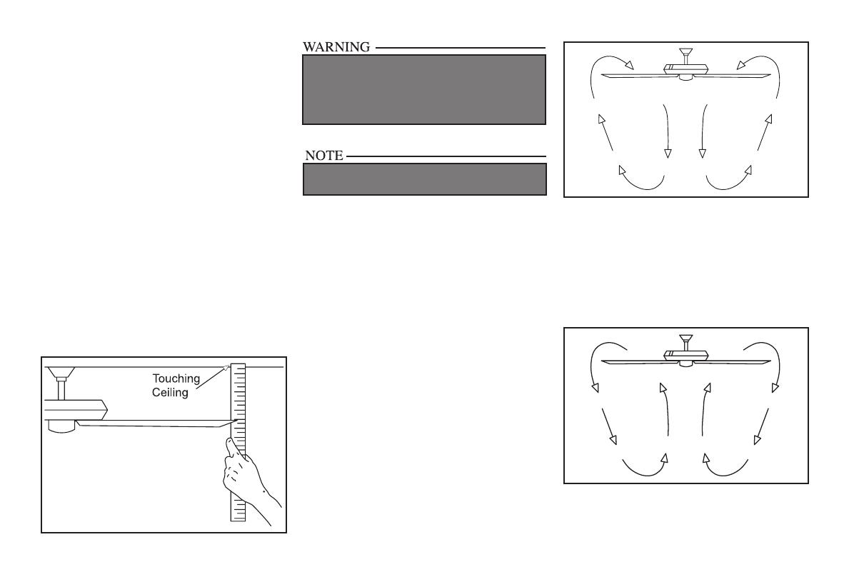
Blade Balancing
All blades are grouped by weight. Because nat-
ural woods vary in density, the fan may wobble
even though the blades are weight matched. The
following procedure should correct most fan
wobble. Check after each step.
1. Check that all blade and blade bracket
screws are secure.
2. Most fan wobble problems are caused when
blade levels are unequal. Check this level by
selecting a point on the ceiling above the tip
of one of the blades. Measure from a point
on the center of each blade to the point on the
ceiling. Measure this distance as shown in
Figure 16. Rotate the fan until the next blade
is positioned for measurement. Repeat for
each blade. Measurement deviations should
within 1/8”. Run the fan for 10 minutes.
3. Use the enclosed Blade Balancing Kit if the
blade wobble is still noticeable.
TO REDUCE THE RISK OF PERSONAL INJURY,
DO NOT BEND THE BLADE HOLDERS WHILE
INSTALLING, BALANCING THE BLADES, OR
CLEANING THE FAN. DO NOT INSERT FOREIGN
OBJECTS BETWEEN ROTATING BLADES.
Operating your Fan
Turn on the power and check the operation of
the fan. The pull chain controls the fan speeds
as follows: 1 pull - High, 2 pulls - Medium, 3
pulls - Low and 4 pulls - Off
Speed settings for warm or cool weather depend
on factors such as room size, ceiling height,
number of fans, and so on.
The slide switch controls the direction: forward
(switch left) or reverse (switch right).
Warm weather - (Forward) A downward
air ow creates a cooling effect as shown in
Figure 17. This allows you to set your air condi-
tioner on a higher setting without affecting your
comfort.
WAIT FOR FAN TO STOP BEFORE REVERSING
THE DIRECTION OF BLADE ROTATION.
Cool weather - (Reverse) An upward air ow
moves warm air off the ceiling are as shown in
Figure 18. This allows you to set your heating
unit on a lower setting without affecting your
comfort.

10. Care of Your Fan and Troubleshooting
Care of Your Fan
Here are some suggestions to help you
maintain your fan.
1. Because of the fan’s natural movement,
some connections may become loose.
Check the support connections, brackets,
and blade attachments twice a year. Make
sure they are secure. (It is not necessary to
remove fan from ceiling.)
2. Clean your fan periodically to help maintain
its new appearance over the years. Do not
use water when cleaning, this could damage
the motor, or the wood or possibly cause
an electrical shock. Use only a soft brush
or lint-free cloth to avoid scratching the
nish. The plating is sealed with a lacquer
to minimize discoloration or tarnishing.
Warning - Make sure the power is off
before cleaning your fan.
3. You can apply a light coat of furniture pol-
ish to the wood for additional protection
and enhanced beauty. Cover small scratches
with a light application of shoe polish.
4. There is no need to oil your fan.
The motor has permanently lubricated
sealed ball bearings.
MAKE SURE THE POWER IS OFF AT THE ELECTRICAL PANEL BOX BE-
FORE YOU ATTEMPT TO MAKE ANY REPAIRS. REFER TO THE SECTION,
“MAKING ELECTRICAL CONNECTIONS.”
Fan will not start
Fan sounds noisy
1. Check main and branch circuit fuses or breakers
2. Check line wire connections to the fan and switch wire connections in
the switch housing. CAUTION: Make sure main power is off.
1. Make sure all motor housing screws are snug.
2. Make sure the screws that attach the fan blade bracket to the motor hub
are tight.
3. Make sure wire nut connections are not rattling against each other or
the interior wall of the switch housing.
CAUTION: Make sure power is off.
4. Allow a 24-hour “breaking in” period. Most noises associated with a
new fan disappear during this time.
5. If using the Ceiling Fan light kit, make sure the screws securing the
glassware are tight. Check that the light bulb is also secure.
6. Make sure the canopy is a short distance from the ceiling.
It should not touch the ceiling.
7. Make sure your outlet box is secure and rubber isolator pads were used
between the mounting plate and outlet box.
Troubleshooting
Problem Solution

Specications 11.
FAN SIZE SPEED VOLTS AMPS WATTS RPM CFM
NET
WEIGHT
GROSS
WEIGHT
CUBE FEET
48”
Low 120 0.26 13 80 1969
20.2
Lbs
22
Lbs
1.25Med 120 0.40 34 130 3286
High 120 0.60 70 200 4762
These are approximate measures. They do not include Amps and Wattage used by the light kit.
Distributed by Home Depot U.S.A., Inc.
2455 Paces Ferry Rd. N.W. Atlanta, Georgia 30339
Vendor Number: 11688

12. Warranty Information
Hampton Bay Lifetime Limited Warranty
Lifetime Warranty on Motor
Hampton Bay warrants the fan motor to be free from defects in workmanship and material present at
time of shipment from the factory for a lifetime after the date of purchase by the original purchaser.
Hampton Bay also warrants that all other fan parts, excluding any glass or acrylic blades, to be free
from defects in workmanship and material at the time of shipment from the factory for a period of
one year after the date of purchase by the original purchaser. We agree to correct such defects with-
out charge or at our option replace with a comparable or superior model if the product is returned to
Hampton Bay. To obtain warranty service, you must present a copy of the receipt as proof of pur-
chase. All costs of removing and reinstalling the product are your responsibility. Damage to any part
such as by accident or misuse or improper installation or by afxing any accessories, is not covered
by this warranty. Because of varying climatic conditions, this warranty does not cover any changes
in plated nishes, including rusting, pitting, corroding, tarnishing or peeling. Brass nishes of this
type give their longest useful life when protected from varying weather conditions. A certain amount
of “wobble” is normal and should not be considered a defect. Servicing performed by unauthorized
persons shall render the warranty invalid. There is no other express warranty. Hampton Bay hereby
disclaims any and all warranties, including but not limited to, those of merchantability and tness
for a particular purpose to the extent permitted by law. The duration of any implied warranty which
cannot be disclaimed is limited to the time period as specied in the express warranty. Some states
do not allow limitation on how long an implied warranty lasts, so the above limitation may not apply
to you. Hampton Bay shall not be liable for incidental, consequential, or special damages arising out
of or in connection with product use or performance except as may otherwise be accorded by law.
Some states do not allow the exclusion of incidental or consequential damages, so the above exclu-
sion or limitation may not apply to you. This warranty gives specic legal rights, and you may also
have other rights which vary from state to state. This warranty supersedes all prior warranties. Ship-
ping costs for any return of product as part of a claim on the warranty must be paid by the customer.
IMPORTANT NOTE:
To ensure warranty service, if ever
necessary, please register your fan at:
gpwarranty.com
You must present a copy of the original
purchase receipt to obtain warranty service.
G.P. WARRANTY SERVICE CENTER, INC.
WARRANTY SECTION
1951 N.W. 22nd STREET
FORT LAUDERDALE, FLORIDA 33311
Attach receipt here for
easy location.
7.
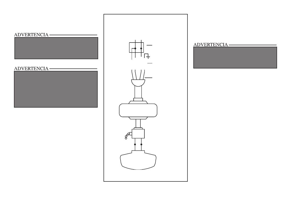
Figura 13
5. Gira las tuercas de conexión del cable hacia
arriba y coloca el cableado dentro de la caja
eléctrica.
Finalizar la instalación
del ventilador
MONTAJE DE TECHO ESTÁNDAR
1. Alinea las ranuras de cierre de la cubierta
de techo con los dos tornillos del soporte de
montaje. Alza para enganchar las ranuras y
gira de izquierda a derecha para asegurar en
su sitio. Ajusta con rmeza los dos tornillos
de montaje.
2. Instala los dos tornillos de montaje restantes
en los oricios de la cubierta y aprieta
rmemente.
3. Instala el aro de cubierta decorativa
alineando las ranuras del aro con los tornillos
en la cubierta. Rota el aro en sentido de las
manecillas del reloj para jarlo.
4. Ahora puedes proceder a montar las aspas
del ventilador.
El diagrama muestra un kit de luces opcional
CIRCUITO DE SUMINISTRO
Caja
eléctrica
Negro
Azul
Blanco
Blanco
Negro
Verde
Cable
terminal a
tierra verde
Tierra al
tubo bajante
Blanco
Blanco
Azul
Negro
PARA REDUCIR EL RIESGO DE INCENDIO O DESCARGA
ELÉCTRICA, NO UTILICES ESTE VENTILADOR CON
NINGÚN DISPOSITIVO DE CONTROL DE VELOCIDAD DE
ESTADO SÓLIDO, DE MONTAJE EN PARED. EL CIRCUITO
ELECTRÓNICO SE DAÑARÁ EN FORMA PERMANENTE.
CADA TUERCA DEL CABLE (CONECTOR DE CABLE)
PROVISTA CON ESTE VENTILADOR ESTÁ DISEÑADA
PARA ACEPTAR CABLES DOMÉSTICOS DE MÁXIMO UN
CALIBRE 12 Y DOS CABLES DEL VENTILADOR. SI TIENES
UN CABLEADO DOMÉSTICO DE CALIBRE SUPERIOR A
12, O MÁS DE UN CABLE DOMÉSTICO PARA CONECTAR
EL CABLEADO DEL VENTILADOR, CONSULTA A UN
ELECTRICISTA PARA EL TAMAÑO ADECUADO DE TUERCAS
DE CABLE.
CUANDO USES EL MONTAJE DE TUBO BAJANTE Y
BOLA ESTÁNDAR, LA PESTAÑA EN EL ARO EN LA PARTE
INFERIOR DE LA PLACA DE MONTAJE DEBE ENCAJAR EN
LA RANURA DE LA BOLA DE SOPORTE. SI NO ENCAJA
CORRECTAMENTE, SE PUEDE DAÑAR EL CABLEADO.

MONTAJE CERCA DEL TECHO
1. Con cuidado desengancha el ventilador del
soporte de montaje y alinea las ranuras de
cierre de la cubierta del techo con los dos
tornillos en la placa de montaje. Alza para
enganchar las ranuras y gira de izquierda a
derecha para trabar en su sitio. Ajusta con
rmeza los dos tornillos de montaje.
2. Instala los dos tornillos de montaje restantes
en los oricios de la cubierta y aprieta
rmemente.
3. Instala el aro de cubierta decorativa
alineando las ranuras del aro con los tornillos
en la cubierta. Rota el aro en sentido de las
manecillas del reloj para jarlo.
4. Ahora puedes proceder a montar las aspas
del ventilador.
8.
Cómo montar
las aspas del ventilador
1. Fija el aspa a su soporte con los tornillos
según se muestra en la Figura 14. Observa
que las arandelas de goma están jadas en
el soporte del aspa. Inserta el tornillo en el
soporte. Repite para los otros dos tornillos.
2. Aprieta todos los tornillos de manera rme.
3. Ajusta el brazo del aspa al motor insertando
el poste de alineación dentro de la ranura
de la parte inferior del motor y aprieta los
Figura 14
Figura 15
tornillos del soporte del aspa. Por favor,
ten en cuenta que los tornillos del soporte
de aspa están previamente instalados en el
soporte del aspa (Figura 15).
4. Repite los pasos 1-3 para las aspas restantes.
Cómo montar
la caja del interruptor
1. Conecta los enchufes con adaptador que
salen del fondo del motor con el enchufe de
la caja de interruptores.
2. Monta la caja de interruptores en la placa
negra debajo del motor alineando los cuatro
oricios de tornillo y asegurándolo con los
cuatro tornillos cónicos provistos.
LAS RANURAS DE CIERRE DE LA CUBIERTA DEL TECHO
SÓLO SIRVEN DE AYUDA DURANTE LA INSTALACIÓN.
NO DEJES SIN SUPERVISIÓN EL ENSAMBLADO DEL
VENTILADOR HASTA QUE LOS CUATRO TORNILLOS DE LA
CUBIERTA SE FIJEN Y AJUSTEN FIRMEMENTE.
RETIRA LOS TOPES DE GOMA SOBRE LA PLACA NEGRA
DEBAJO DEL MOTOR PARA INSTALAR LAS ASPAS AL
MOTOR. VUELVE A COLOCAR LOS TOPES DE GOMA
PARA EVITAR QUE INGRESE EL AGUA A LA CAJA DEL
INTERRUPTOR Y REDUCIR EL RIESGO DE INCENDIOS,
DESCARGAS ELÉCTRICAS U OTRAS LESIONES
PERSONALES.
/