Page is loading ...

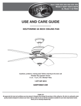
52” Minorca
Ceiling Fan by Hampton Bay
Dual-Mount Installation
Aero-Breeze™ Technology
Moves up to 25% More Air
3-Speed Reverse Function for
Year-Round Comfort and Savings
Handheld Remote Control
QUESTIONS, PROBLEMS, MISSING PARTS:
Before returning to your local Home Depot, please call our
Customer Service Team at 1-877-527-0313 or visit www.homedepot.com.
Please reference your SKU (434 071 gilded mahogany, S/O 435 265, 705 137 brushed nickel, S/O 707 353)
or UPC (082392 266912 gilded mahogany, 082392 266110 brushed nickel).
Thank you for purchasing this Hampton Bay ceiling
fan. This product has been manufactured with the
highest standards of safety and quality. The nish
of this fan is weather resistant, but over time will
naturally weather and fade.
Safety Rules ...............................................1
Unpacking Your Fan .................................2
Installing Your Fan ...................................3
Operating Your Fan .................................. 9
Operating Your Remote Control .............10
Care of Your Fan ....................................... 11
Troubleshooting .........................................11
Specications .............................................12
Warranty Information ..............................13
Table of Contents
UL Model Number: 52-MNC

1. To reduce the risk of electric shock, insure electricity
has been turned off at the circuit breaker or fuse box
before beginning.
2. All wiring must be in accordance with the National
Electrical Code ANSI/NFPA 70-1999 and local electrical
codes. Electrical installation should be performed by a
qualied licensed electrician.
3. WARNING: To reduce the risk of re or electric shock, do
not use this fan with any solid-state speed control device.
4. CAUTION: To reduce the risk of personal injury, use only
the screws provided with the outlet box.
5. The outlet box and support structure must be securely
mounted and capable of reliably supporting 35 lbs. (15.9
kg). Use only UL Listed outlet boxes marked “Acceptable
for Fan Support of 35 lbs. (15.9 kg) or less.”
6. The fan must be mounted with a minimum of 7 feet
clearance from the trailing edge of the blades to the oor.
7. Do not operate reversing switch while fan blades are in mo-
tion. Fan must be turned off and blades stopped before re-
versing blade direction.
8. Avoid placing objects in path of the blades.
9. To avoid personal injury or damage to the fan and
other items, be cautious when working around or
cleaning the fan.
10. Do not use water or detergents when cleaning the fan or fan
blades. A dry dust cloth or lightly dampened cloth will be
suitable for most cleaning.
11. After making electrical connections, spliced conductors
should be turned upward and pushed carefully up into
outlet box. The wires should be spread apart with the
grounded conductor and the equipment-grounding
conductor on one side of the outlet box, and the ungrounded
conductor on the other side of the outlet box.
12. Electrical diagrams are for reference only. Light kits that
are not packed with the fan must be UL Listed and marked
suitable for use with the model fan you are installing.
Switches must be UL General Use Switches. Refer to the
instructions packaged with the light kits and switches for
proper assembly.
13. All set screws must be checked and retightened where
necessary before installation.
Safety Rules 1.
READ AND SAVE THESE INSTRUCTIONS
TO REDUCE THE RISK OF SHOCK. THIS FAN MUST BE INSTALLED
WITH AN ISOLATION WALL CONTROL/SWITCH.
TO REDUCE THE RISK OF FIRE, ELECTRIC SHOCK OR PERSONAL
INJURY, MOUNT TO OUTLET BOX MARKED “ACCEPTABLE FOR FAN
SUPPORT OF 35LBS. (15.9 KG) OR LESS”, AND USE SCREWS PRO
-
VIDED WITH THE OUTLET BOX.
TO REDUCE THE RISK OF PERSONAL INJURY, DO NOT BEND THE
BLADE BRACKETS WHEN INSTALLING THE BRACKETS, BALANCING
THE BLADES, OR CLEANING THE FAN.

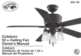
a. Blade Attachment Hardware
(15 Screws)
b. Mounting Hardware
(1 bolt, 1 clevis pin, 3 plastic wire
connectors)
c. Blade Bracket Attachment Hardware
(10 screws)
7. Blades (5)
8. Blade Bracket Set (5)
9. Glass Bowl
10. Hand unit/Receiver (Battery included)
11. Bulbs (6)
1. Mounting Plate (inside canopy)
2. Ball/Downrod Assembly
3. Canopy
4. Fan Motor Assembly
5. Light Kit with nial pre-attached
6. Decorative Glass Housing
2. Unpacking Your Fan
IMPORTANT: THIS PRODUCT AND/OR COMPONENTS ARE COVERED
BY ONE OR MORE OF THE FOLLOWING U.S. PATENTS: 5,947,436;
5,988,580; 5,971,573; 6,010,306; 6,039,541; 6,046,416 AND OTHER
PATENTS PENDING.
IMPORTANT:
PLEASE REMOVE CARDBOARDS ON THE BOTTOM OF THE
FAN BEFORE INSTALLING BLADES OR TESTING MOTOR.
Unpack your fan and check the contents. You should have the following items:
1
2
3
4
5
6
7
8
9
10
11
(2PCS)
(4PCS)
a
b
c

Installing Your Fan 3.
Tools Required
Phillips screw driver, straight slot screw
driver, adjustable wrench, step ladder, and
wire cutters.
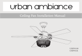
Mounting Options
If there isn’t an existing outlet box, then read
the following instructions. Disconnect the
power by removing fuses or turning off
circuit breakers.
Secure the outlet box directly to the building
structure. Use appropriate fasteners and
building materials. The outlet box and its
support must be able to fully support the
moving weight of the fan (at least 35 lbs.)
Do not use plastic outlet boxes.
Figures 1, 2, and 3 are examples of different
ways to mount the outlet box.
Outlet Box
Note: You may need a longer downrod to
maintain proper blade clearance when install-
ing on a steep, sloped ceiling. The maximum
angle allowable is 30˚. If the canopy touches
downrod, remove the decorative canopy
bottom cover and turn the canopy 180˚ before
attaching the canopy to the mounting plate.
Outlet Box
To hang your fan where there is an existing
xture but no ceiling joist, you may need an
installation hanger bar as shown in Figure 4
(available at your Hampton Bay retailer).
TO REDUCE THE RISK OF FIRE, ELECTRIC
SHOCK OR PERSONAL INJURY, MOUNT TO
OUTLET BOX MARKED “ACCEPTABLE FOR FAN
SUPPORT OF 35LBS. (15.9 KG) OR LESS”, AND
USE SCREWS PROVIDED WITH THE OUTLET
BOX. OUTLET BOXES COMMONLY USED FOR
THE SUPPORT OF LIGHTING FIXTURES MAY
NOT BE ACCEPTABLE FOR FAN SUPPORT
AND MAY NEED TO BE REPLACED. CONSULT A
QUALIFIED ELECTRICIAN IF IN DOUBT.
Figure 1
Figure 2
Figure 4
Figure 3

IF YOU FEEL THAT YOU DO NOT HAVE
ENOUGH ELECTRICAL WIRING KNOWL-
EDGE OR EXPERIENCE, HAVE YOUR
FAN INSTALLED BY A LICENSED ELEC-
TRICIAN.
1. Remove the canopy ring from the canopy
by turning the ring to the right until it
unlocks (Figure 7).
2. Remove the mounting plate from the
canopy by loosening the four screws on
the top of the canopy. Remove the two
non-slotted screws and loosen the slotted
screws. This will enable you to remove the
mounting plate (Figure 8).
4.
Turn Canopy Ring To Remove
Figure 7
Remove
Loosen But Do
Not Remove
Figure 8
Attaching the
Fan Blades
NOTE: Your fan blade are reversible. Select the
blade side nish which best accentuates your
decor.
1. Attach blade to blade bracket using the
screws supplied (Figure 5). Start a screw
into the bracket. Repeat for the two remain-
ing screws.
2. Tighten each screw securely.
3. Rotate the center ywheel until the blade
bracket screw holes in the center ywheel
are visible from the cut-out in the top light
kit plate (Figure 6).
4. Insert the blade/blade bracket assembly
through the hole in the side of the center
y wheel, align the two screws holes in
the blade bracket with the screw holes in
Figure 5
Blade Bracket
Screws
Blade
the center ywheel and secure with screws
supplied (Figure 6).
5. Repeat steps 1-4 for the remaining blades.
Screws
Cut-Out In The
Blade/Blade
Hole For Blade
Center
Top Light
Kit Plate
Bracket
Assembly
Bracket Insert
Flywheel
Figure 6
Hanging the Fan
REMEMBER to turn off the pow-
er. Follow the steps below to hang your
fan properly.
NOTE: This fan is recommended for the stan-
dard ceiling mounting using the downrod with
ball and socket mounting. When using stan-
dard ceiling installation, the distance from the
ceiling to the bottom of the fan blades will be
approximately 16 inches.
THE FAN MUST BE MOUNTED WITH A
MINIMUM OF 7 FEET CLEARANCE FROM
THE TRAILING EDGE OF THE BLADES
TO THE FLOOR.

4. Loosen, but do not remove, the set
screws on the collar on the top of the
motor housing.
5. Align the holes at the bottom of the
downrod with the holes in the collar
on top of the motor housing (Figure 9).
Carefully insert the bolt through the
holes in the collar and downrod. Be care-
ful not to jam the bolt against the wir-
ing inside the downrod. Insert the
clevis pin through the hole near the end
of the hanger pin until it snaps into its
locked position, as noted in the circle inset
of Figure 9.
6. Re-tighten the set screws on the collar on top
of the motor housing.
5.
FAILURE TO PROPERLY INSTALL LOCKING PIN
AS NOTED IN STEP 5 COULD RESULT IN THE
FAN LOOSENING AND POSSIBLY FALLING.
Figure 10
Screws
And Rubber
Washers
Sockets
Bulbs
Reversing
Switch
3. Route the wires exiting the top of the fan
motor through the decorative glass housing.
Then route the wires through the canopy
ring and then the canopy. Continue by rout-
ing the wires through the ball/downrod as-
sembly (Figure 9).
Pin in
Position
Locked
Canopy
Motor Wires
Ring
Canopy
Decorative
Housing
Glass
Hanger Pin
Tighten
Screws
Motor Collar
Locking
Pin
Downrod/Ball
Assembly
Figure 9
Installing the Top
Glass Housing
The glass housing is fragile, use care
when installing the fan.
1. Remove the two screws and rubber wash-
ers pre-installed on the top of the fan motor
assembly.
2. Carefully place the decorative glass housing
onto the fan motor assembly (Figure 10).
3. Align the two screw holes in the decorative
glass housing with the screw holes on the
top of the fan motor assembly and securing
with the screws and washers that were re-
moved in step 1.
4. Install 4 candelabra base bulbs (Max. 15
watts, provided) to the sockets on the fan
motor assembly.
120V Wires
Ceiling
Mounting
Plate
UL Listed
Outlet Bo
x
Slide Mounting
Plate Over
Screw Heads
Hook
Mounting Screws
(Supplied with
Outlet Box)

6.
EACH WIRE NUT (WIRE CONNECTOR) SUP-
PLIED WITH THIS FAN IS DESIGNED TO ACCEPT
UP TO ONE 12 GAUGE HOUSE WIRE AND TWO
WIRES FROM THE FAN. IF YOU HAVE LARGER
THAN 12 GAUGE HOUSE WIRING OR MORE
THAN ONE HOUSE WIRE TO CONNECT TO THE
FAN WIRING, CONSULT AN ELECTRICIAN FOR
THE PROPER SIZE WIRE NUTS TO USE.
Installing Fan to
the Outlet Box
WHEN MOUNTING THE FAN ON A SLOPED
CEILING, THE STANDARD BALL/DOWNROD
MOUNTING METHOD MUST BE USED. MAKE
SURE THE MOUNTING BRACKET SLOTS ARE
ON THE LOWER SIDE BY SLIDING THE MOUNT-
ING BRACKET FROM THE TOP DOWN.
1. Pass the 120-volt supply wires through the
center hole in the ceiling mounting bracket
as shown in Figure 9.
2. Install the ceiling mounting plate on the
outlet box, sliding the mounting plate over
the two screws provided with the outlet box
(Figure 9). If necessary, use leveling wash-
ers (not included) between the mounting
plate and the outlet box. Note that the at
side of the mounting plate is to be toward
the outlet box.
3. Securely tighten the two mounting screws.
4. Carefully lift the fan assembly up to the ceil-
ing mounting plate. Make sure the tab on the
mounting plate socket is properly seated in
the groove in the hanger ball.
Making the Electrical
Connections
REMEMBER to disconnect the power. If
you feel you do not have enough electrical
wiring knowledge or experience, have your fan
installed by a licensed electrician.
Follow these steps to connect the fan and
receiver to your household wiring (or fol-
low the instructions included along
with the remote control). Use the wire
connection nuts supplied with your fan. Se-
cure the wire connection nuts with electrical
tape. Make sure there are no loose strands or
connections.
1. Connect the ground conductor of the 120v
supply (this may be a bare wire or a wire
with green colored insulation) to the green
ground lead(s) of the fan (Figure 11).
2. Connect the fan motor white wire to the
receiver white wire using a wire nut.
3. Connect the fan motor black wire to the
receiver black wire using a wire nut.
4. Connect the fan motor blue wire to the
receiver blue wire using a wire nut.
5. Connect the receiver red wire to the supply
black (hot) wire using a wire nut.
ELECTRICAL DIAGRAMS ARE FOR REFERENCE
ONLY. OPTIONAL USE OF ANY LIGHT KIT SHALL
BE UL LISTED AND MARKED SUITABLE FOR
USE WITH THIS FAN.
6. Connect the receiver white wire to the sup-
ply white wire (neutral) wire using a wire
nut.
7. After connecting the wires, spread them
apart so that the green and white wires are
on one side of the outlet box and the black
wire is on the other side.
8. Turn the wire connecting nuts upward and
push the wiring into the outlet box.

7.
Figure 11
WHITE
BLACK
BLUE
BLACK
WHITE
WHITE
Outlet
Box
Grounding
Green
Lead
Ground
to
Downrod
SUPPLY CIRCUIT
Receiver
WHITE
RED
WHITE
BLACK
BLUE
WHITE
BLACK
BLUE
Finishing the Fan
Installation
1. Align the four screw holes in the canopy
with the four screw holes in the mounting
plate.
2. Secure the canopy in place by using the four
mounting screws that were removed in step
2 as described on page 4.
3. You may now proceed to install the decora-
tive support rods.
Installing the Light
Kit/ Glass Shade
REMEMBER to disconnect the power.
THE GLASS IS FRAGILE, USE CARE
WHEN INSTALLING THE LIGHT KIT AND
THE GLASS SHADE.
1. Remove the three mounting screws on the
light kit switch cup.
2. Connect the wires exiting the light kit brack-
et below the fan motor with the wires from
the light kit switch cup, black to blue and
white to white (Figure 12).
3. Carefully push all the wires into the light kit
switch cup.
NOTE: ALLOW THE BULBS TO COOL
COMPLETELY BEFORE TOUCHING OR
REPLACING THE BULBS TO AVOID ACCI-
DENTAL BURNING OF THE SKIN.
DO NOT OVERTIGHTEN THE FINIAL,
OVERTIGHTENING THE FINIAL MAY
CAUSE THE GLASS TO BREAK.
4. Slide the light kit switch cup and secure it to
the light kit bracket using the three screws
removed in step 1.
5. Remove the nial, hex nut and rubber wash-
er on the bottom of the light kit assembly.
6. With the power off, insert the light bulbs
into the light kit sockets, Max. 60 watt can-
delabra base bulbs provided.
7. Raise the glass shade up against the light
plate of the fan motor assembly. Place the
rubber washer and then the hex nut removed
in step 5. Firmly tighten the hex nut to hold
the glass bowl in place (Figure 12).
8. Re-install and nger tighten the nial.
OVER LAMPING THE FAN WILL RESULT IN
THE FAN LIGHTS SHUTTING DOWN UNTIL THE
PROPER WATTAGE OF BULBS ARE INSTALLED.
RESET THE LIGHTS BY TURNING OFF, RE-
PLACE BULBS WITH THE CORRECT WATTAGE
BULBS, TURN POWER ON.

8.
Figure 13
Figure 12
Blade Balancing
All blades are grouped by weight. Because nat-
ural woods vary in density, the fan may wobble
even though the blades are weight matched. The
following procedure should correct most fan
wobble. Check after each step.
1. Check that all blade and blade bracket
screws are secure.
2. Most fan wobble problems are caused when
blade levels are unequal. Check this level by
selecting a point on the ceiling above the tip
of one of the blades. Measure from a point
on the center of each blade to the point on the
ceiling. Measure this distance as shown in
Figure 13. Rotate the fan until the next blade
is positioned for measurement. Repeat for
each blade. Measurement deviations should
within 1/8”. Run the fan for 10 minutes.
3. If the fan continues to wobble please contact
Customer Service and a balacing kit will be
sent to you at no charge.
TO REDUCE THE RISK OF PERSONAL INJURY,
DO NOT BEND THE BLADE HOLDERS WHILE
INSTALLING, BALANCING THE BLADES, OR
CLEANING THE FAN. DO NOT INSERT FOREIGN
OBJECTS BETWEEN ROTATING BLADES.
Sockets
Mounting
Bulbs
Finial
Glass Shade
Screws
White
White
Light Kit
Switch
Cup
Blue
Black
Light Kit
Bracket
Rubber Washer
Hex Nut

Operating Your Fan 9.
Figure 14
Figure 15
Remote Control - Your fan is equipped with a
remote control to operate the speed and lights
of your new ceiling fan. For more information
on how to install the remote control, see the re-
mote control instruction along with the remote
control components.
Speed settings for warm or cool weather depend
on factor such as the room size, ceiling height,
number of fans and so on.
The fan shipped from the factory with the re-
versing switch positioned to circulate air down-
ward. If airow is desired in the opposite direc-
tion, turn your fan off and wait for the blades
to stop turning, then slide the reversing switch
(located at the top of the motor housing, refer to
gure 10 on page 5) to opposite position, and
turn fan on again. The fan blades will turn in the
opposite direction and reverse the airow.
1. Speed - The remote features Low, Med, Hi
and Off buttons to select the desired speed
of operation and turn the fan On or Off.
2. Lights - To control the light kit, the remote
features a light/Dimmer button.
WAIT FOR FAN TO STOP BEFORE REVERSING
THE DIRECTION OF BLADE ROTATION.
Warm weather - (Forward) A downward air
ow creates a cooling effect as shown in Fig-
ure 14. This allows you to set your air condi-
tioner on a higher setting without affecting your
comfort.
Cool weather - (Reverse) An upward air ow
moves warm air off the ceiling are as shown in
Figure 15. This allows you to set your heating
unit on a lower setting without affecting your
comfort.

10. Operating Your Remote Control
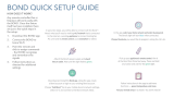
Setting the Code
This unit has 16 different code combinations. To
set the code, perform the following steps:
A. Setting the code on the transmitter:
a. Remove the battery cover. Press rmly
below arrow and slide battery cover off.
b. Slide code switches to your choice of up
or down position. (Factory setting is all up).
B. Setting the code on the receiver.
a. Slide code switches to the same position
as set on your transmitter.
b. Replace battery cover on transmitter.
CAUTION:
Ceiling angle shall not exceed 30 degrees.
Controller Models: FAN28R-240W
Installing Receiver
WARNING: To reduce the risk of re or elec-
trical shock, remember to disconnect power.
The electrical wiring must meet all local and
national electrical code requirements. Electri-
cal source and fans must be 110/120 volt, 60Hz.
Maximum fan motor amps: 1.0
Maximum light watts: 240 incandescent only.
Transmitter Operation
NOTE: This remote is equipped with 16 code combinations. To prevent possible interference
from or to other remote units such as garage door openers, car alarm or security system, simply
change the combination code but be sure that the code on both the hand held transmitter and
receiver in the fan are matched.
Install a 9 volt battery (included).
Operating the Fan:
Hi Key - High Speed Med Key - Medium Speed Low Key - Low Speed
Off Key - Power Off Light/Dimmer Key- Dim the light with memory
Installing Receiver
A. Wire Connection:
Fan Green Wire ............................................................... Bare Supply Wire
Red Receiver Wire (AC IN L) ........................................ Black Supply Wire
White Receiver Wire (AC IN N) ..................................... White Supply Wire
White Receiver Wire (TO MOTOR N) ........................... White Fan Wire
Black Receiver Wire (TO MOTOR L) ............................ Black Fan Wire
Blue Receiver Wire (FOR LIGHT) ................................. Blue Light Wire
NOTE: If other fan wires are a different color, have this unit installed by a licensed electrician.
B. Lay the brown antenna wire on top of the receiver, and slide the receiver into the mounting
bracket.

Care of Your Fan and Troubleshooting 11.
Care of Your Fan
Here are some suggestions to help you
maintain your fan.
1. Because of the fan’s natural movement,
some connections may become loose.
Check the support connections, brackets,
and blade attachments twice a year. Make
sure they are secure. (It is not necessary to
remove fan from ceiling.)
2. Clean your fan periodically to help maintain
its new appearance over the years. Do not
use water when cleaning, this could damage
the motor, or the wood or possibly cause
an electrical shock. Use only a soft brush
or lint-free cloth to avoid scratching the
nish. The plating is sealed with a lacquer
to minimize discoloration or tarnishing.
Warning - Make sure the power is off
before cleaning your fan.
3. You can apply a light coat of furniture pol-
ish to the wood for additional protection
and enhanced beauty. Cover small scratches
with a light application of shoe polish.
4. There is no need to oil your fan.
The motor has permanently lubricated
sealed ball bearings.
MAKE SURE THE POWER IS OFF AT THE ELECTRICAL PANEL BOX BE-
FORE YOU ATTEMPT TO MAKE ANY REPAIRS. REFER TO THE SECTION,
“MAKING ELECTRICAL CONNECTIONS.”
Fan will not start
Fan sounds noisy
1. Check main and branch circuit fuses or breakers
2. Check line wire connections to the fan and switch wire connections in
the switch housing. CAUTION: Make sure main power is off.
3. Check batteries in the transmitter. Does the red LED light come on? Are
you standing close enough to the fan? (Normal range is 10-20 feet.) Are
the dip switch settings the same on the transmitter (hand unit) and re-
ceiver? REMEMBER TO TURN OFF POWER SUPPLY BEFORE
CHECKING THE DIP SWITCH SETTINGS IN RECEIVER.
1. Make sure all motor housing screws are snug.
2. Make sure the screws that attach the fan blade bracket to the motor hub
are tight.
3. Make sure wire nut connections are not rattling against each other or
the interior wall of the switch housing.
CAUTION: Make sure power is off.
4. Allow a 24-hour “breaking in” period. Most noises associated with a
new fan disappear during this time.
5. If using the Ceiling Fan light kit, make sure the screws securing the
glassware are tight. Check that the light bulb is also secure.
6. Make sure the canopy is a short distance from the ceiling.
It should not touch the ceiling.
7. Make sure your outlet box is secure and rubber isolator pads were used
between the mounting bracket and outlet box.
Troubleshooting
Problem Solution

12. Specications
FAN SIZE SPEED VOLTS AMPS WATTS RPM CFM
NET
WEIGHT
GROSS
WEIGHT
CUBE FEET
52”
Low 120 0.32 15 60 2387
23.3
Lbs
26.4
Lbs
1.93Med 120 0.41 29 98 3911
High 120 0.49 56 150 5873
These are approximate measures. They do not include Amps and Wattage used by the light kit.
Distributed by
Your Other Warehouse LLC
12100 Little Cayman Dr.
Baton Rouge, LA 70809
Vendor number: 219030

Warranty Information 13.
Hampton Bay Lifetime Limited Warranty
Lifetime Warranty on Motor
Hampton Bay warrants the fan motor to be free from defects in workmanship and material present at
time of shipment from the factory for a lifetime after the date of purchase by the original purchaser.
Hampton Bay also warrants that all other fan parts, excluding any glass or acrylic blades, to be free
from defects in workmanship and material at the time of shipment from the factory for a period of
one year after the date of purchase by the original purchaser. We agree to correct such defects without
charge or at our option replace with a comparable or superior model if the product is returned to
Hampton Bay. To obtain warranty service, you must present a copy of the receipt as proof of purchase.
All costs of removing and reinstalling the product are your responsibility. Damage to any part such
as by accident or misuse or improper installation or by afxing any accessories, is not covered by
this warranty. Because of varying climatic conditions, this warranty does not cover any changes in
plated nishes, including rusting, pitting, corroding, tarnishing or peeling. Brass nishes of this type
give their longest useful life when protected from varying weather conditions. A certain amount of
“wobble” is normal and should not be considered a defect. Servicing performed by unauthorized
persons shall render the warranty invalid. There is no other express warranty. Hampton Bay hereby
disclaims any and all warranties, including but not limited to, those of merchantability and tness
for a particular purpose to the extent permitted by law. The duration of any implied warranty which
cannot be disclaimed is limited to the time period as specied in the express warranty. Some states
do not allow limitation on how long an implied warranty lasts, so the above limitation may not apply
to you. Hampton Bay shall not be liable for incidental, consequential, or special damages arising
out of or in connection with product use or performance except as may otherwise be accorded by
law. Some states do not allow the exclusion of incidental or consequential damages, so the above
exclusion or limitation may not apply to you. This warranty gives specic legal rights, and you may
also have other rights which vary from state to state. This warranty supersedes all prior warranties.
Shipping costs for any return of product as part of a claim on the warranty must be paid by the
customer.
IMPORTANT NOTE:
To ensure warranty service, if ever
necessary, please register your fan at:
gpwarranty.com
You must present a copy of the original
purchase receipt to obtain warranty service.
G.P. WARRANTY SERVICE CENTER, INC.
WARRANTY SECTION
1951 N.W. 22nd STREET
FORT LAUDERDALE, FLORIDA 33311
Attach receipt here for
easy location.

Especicaciones 12.
TAMAÑO VELOCIDAD VOLTIOS AMPERIOS VATIOS RPM
PIES
CÚB. X
MIN.
PESO
NETO
PESO
BRUTO
PIES CÚB.
52”
Baja 120 0.32 15 60 2387
23.3
Lb
26.4
Lb
1.93Media 120 0.41 29 98 3911
Alta 120 0.49 56 150 5873
Estas medidas son aproximadas. No incluyen ni el amperaje ni el vataje consumido por el kit de luces.
Distribuido por
Your Other Warehouse LLC
12100 Little Cayman Dr.
Baton Rouge, LA 70809
Número del proveedor: 219030
/