Page is loading ...

Version 3/08 - Page 1
Axia Isola
Island Mount Canopy Rangehood
READ THESE INSTRUCTIONS BEFORE YOU START INSTALLING THIS RANGEHOOD
WARNING: - TO REDUCE THE RISK OF A RANGE TOP GREASE FIRE: a) Never leave surface units unattended at high set-
tings. Boilovers cause smoking and greasy spillovers that may ignite. Heat oils slowly on low or medium setting. b) Always
turn hood ON when cooking at high heat or when ambeing food (i.e. Crepes Suzette, Cherries Jubilee, Peppercorn Beef
Flambé). c) Clean ventilating fans frequently. Grease should not be allowed to accumulate on fan or lter. d) Use proper
pan size. Always use cookware appropriate for the size of the surface element.
WARNING: - TO REDUCE THE RISK OF INJURY TO PERSONS IN THE EVENT OF A RANGE TOP GREASE FIRE, OBSERVE
THE FOLLOWING: SMOTHER FLAMES with a close-tting lid, cookie sheet, or metal tray, then turn off the burner. BE CARE-
FUL TO PREVENT BURNS. If the ames do not go out immediately EVACUATE AND CALL THE FIRE DEPARTMENT. NEVER
PICK UP A FLAMING PAN - You may be burned. DO NOT USE WATER, including wet dishcloths or towels - a violent steam
explosion will result. Use an extinguisher ONLY if: 1. You know you have a Class ABC extinguisher, and you already know
how to operate it. 2. The re is small and contained in the area where it started. 3. The re department is being called. 4.
You can ght the re with your back to an exit.
ALL WALL AND FLOOR OPENINGS WHERE THE RANGEHOOD IS INSTALLED MUST BE SEALED.
This rangehood requires at least 24" of clearance between the bottom of the rangehood and the cooking surface or countertop. This
minimum clearance may be higher depending on local building code. For example, for gas ranges, a minimum of 30" may be required.
The maximum depth of overhead cabinets is 13". Overhead cabinets on both sides of this unit must be a minimum of 18" above the
cooking surface or countertop. Consult the cooktop or range installation instructions given by the manufacturer before making any
cutouts. MOBILE HOME INSTALLATION The installation of this rangehood must conform to the Manufactured Home Construction
and Safety Standards, Title 24 CFR, Part 3280 (formerly Federal Standard for Mobile Home Construction and Safety, Title 24, HUD,
Part 280). Four wire power supply must be used and the appliance wiring must be revised. See Electrical Requirements.
LISEZ BIEN CETTE FICHE AVANT D'INSTALLER LA HOTTE
AVERTISSEMENT - POUR MINIMISER LE RISQUE D’UN FEU DE GRAISSE SUR LA TABLE DE CUISSON : a) Ne jamais laisser
un élément de la table de cuisson fonctionner sans surveillance à la puissance de chauffage maximale; un renversement/
débordement de matière graisseuse pourrait provoquer une inammation et le génération de fumée. Utiliser toujours une
puissance de chauffage moyenne ou basse pour le chauffage d’huile. b) Veiller à toujours faire fonctionner le ventilateur de
la hotte lors d’une cuisson avec une puissance de chauffage élevée ou lors de la cuisson d’un mets à amber (i.e. Crepes
Suzette, Cherries Jubilee, Peppercorn Beef Flambé). c) Nettoyer fréquemment les ventilateurs d’extraction. Veiller à ne pas
laisser de la graisse s’accumuler sur les surfaces du ventilateur ou des ltres. d) Utiliser toujours un ustensile de taille ap-
propriée. Utiliser toujours un ustensile de taille adapté à la taille de l’élément chauffant.
AVERTISSEMENT: - POUR PRÉVENIR LES BLESSURES EN CAS DE FEU SUIVRE LES RECOMMANDATIONS SUIVANTES:
ÉTOUFFEZ LE FEU avec un couvercle métallique et fermez le brûleur. Si le feu ne s'éteint pas tout de suite, QUITTEZ LES
LIEUX ET APPELEZ LES POMPIERS. NE TOUCHEZ JAMAIS UNE CASSEROLE EN FLAMMES. N'UTILISEZ JAMAIS DE L'EAU
ou un torchon mouillé pour éteindre le feu - ce qui pourrait causer une explosion de vapeur. N'utilisez un extincteur que
si: 1. Vous avez un modèle ABC et vous connaissez bien son mode d'emploi. 2. Le feu est petit et peu répandu. 3. Les
pompiers sont déjà prévenus. 4. Vous avez une sortie derrière vous.
TOUTE OUVERTURE DANS LE MUR OU LE PLANCHER À PROXIMITÉ DE LA HOTTE DOIT ÊTRE SCELLÉ
Gardez 24 po. de hauteur entre le bas de la hotte et la surface de cuisson. Cette hauteur minimum peut être haute suivant le code
municipal. Par exemple, les cuisinières à gaz peuvent requérir 30 po. de hauteur. Les armoires au-dessus ne dépasseront pas 13 po.
de profondeur. Les armoires au-dessus de chaque côté devront être au moins à 18 po. au-dessus de la surface de cuisson. Consultez
Home Construction and Safety Standards, titre 24 CFR, Section 3280 (anciennement Federal Standard for Mobile Home Construction
and Safety Standards, titre 24 CFR, Section 3280 (anciennement Federal Standard for Mobile Home Construction and Safety, titre 24,
READ AND SAVE THESE INSTRUCTIONS
The Installer must leave these instructions with the homeowner.
The homeowner must keep these instructions for future reference

Version 3/08 - Page 2
VENTING REQUIREMENTS
Determine which venting method is best for your application.
Ductwork can extend either through the wall or the roof.
The length of the ductwork and the number of elbows should
size of the ductwork should be uniform. Do not install two el-
bows together. Use duct tape to seal all joints in the ductwork
around the cap.
Flexible ductwork is not recommended. Flexible ductwork
creates back pressure and air turbulence that greatly
reduces performance.
exhaust duct before making cutouts. Do not cut a joist or stud
unless absolutely necessary. If a joist or stud must be cut, then
a supporting frame must be constructed.
FOR MORE SPECIFIC DUCTWORK INFORMATION, GO
TO PAGE 4.
WARNING - To Reduce The Risk Of Fire, Use Only Metal
Ductwork.
ELECTRICAL REQUIREMENTS
A 120 volt, 60 Hz AC-only electrical supply is required on a
separate 15 amp fused circuit. A time-delay fuse or circuit
breaker is recommended. The fuse must be sized per local
codes in accordance with the electrical rating of this unit as
WITH COPPER WIRE ONLY. Wire sizes must conform to the
requirements of the National Electrical Code, ANSI/NFPA 70
- latest edition, and all local codes and ordinances. Wire size
and connections must conform with the rating of the appliance.
Copies of the standard listed above may be obtained from:
National Fire Protection Association
Batterymarch Park
Quincy, Massachusetts 02269
home.
other enclosed space.
ventilation air.
This appliance should be connected directly to the fused discon-
sheathed copper cable. Allow some slack in the cable so the
appliance can be moved if servicing is ever necessary. A UL
Listed, 1/2" conduit connector must be provided at each end
of the power supply cable (at the appliance and at the junction
box).
When making the electrical connection, cut a 1 1/4" hole in the
wall. A hole cut through wood must be sanded until smooth. A
hole through metal must have a grommet.
WARNING - TO REDUCE THE RISK OF FIRE OR ELECTRIC
SHOCK, do not use this fan with any solid-state speed
control device.
WARNING - TO REDUCE THE RISK OF FIRE, ELECTRI-
CAL SHOCK, OR INJURY TO PERSONS, OBSERVE THE
FOLLOWING: Use this unit only in the manner intended
by the manufacturer. If you have any questions, contact
the manufacturer.
Before servicing or cleaning unit, switch power off at
service panel and lock the service disconnecting means
to prevent power from being switched on accidentally.
When the service disconnecting means cannot be locked,
securely fasten a prominent warning device, such as a tag,
to the service panel.
CAUTION: For General Ventilating Use Only. Do Not Use To
Exhaust Hazardous or Explosive Materials and Vapors.
WARNING - TO REDUCE THE RISK OF FIRE, ELECTRI-
CAL SHOCK, OR INJURY TO PERSONS, OBSERVE THE
FOLLOWING: Installation Work And Electrical Wiring Must
Be Done By Qualied Person(s) In Accordance With All
Applicable Codes And Standards, Including Fire-Rated
Construction.
Sufcient air is needed for proper combustion and exhaust-
ing of gases through the ue (chimney) of fuel burning
equipment to prevent backdrafting. Follow the heating
equipment manufacturer's guideline and safety standards
such as those published by the National Fire Protection
Association (NFPA), and the American Society for Heating,
Refrigeration and Air Conditioning Engineers (ASHRAE),
and the local code authorities.
When cutting or drilling into wall or ceiling, do not damage
electrical wiring and other hidden utilities.
Ducted fans must always be vented to the outdoors.
WARNING
nonmetallic gaskets or other materials, DO NOT
use for grounding.
circuit. A fuse in the neutral or grounding circuit
could result in electrical shock.
as to whether the rangehood is properly grounded.
WARNING
For residential use only.
!
!
Cold Weather installations
An additional back draft damper should be installed to minimize
be installed to minimize conduction of outside temperatures
as part of the vent system. The damper should be on the cold
air side of the thermal break. The break should be as close as
possible to where the vent system enters the heated portion
of the house.

Version 3/08 - Page 4
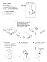
FIGURE 1
TOOLS NEEDED FOR INSTALLATION
PARTS SUPPLIED FOR INSTALLATION
PARTS NEEDED FOR INSTALLATION
OPTIONAL ACCESSORIES AVAILABLE
*Ductless Conversion Kit
For non-vented installations only
* it is highly recommended that professional style
cooking always be vented to the outside
part # 620000042 - Stainless
Replacement Charcoal Filter
For non-vented installations only,
part # 620000041
RANGEHOOD COMPONENTS
A. CANOPY SECTION
B. LOWER CHIMNEY COVER
C. UPPER CHIMNEY COVER
D. LOWER CHIMNEY SUPPORT
E. UPPER CHIMNEY SUPPORT
F. CANOPY SCREWS (short screws)
G. DO NOT USE (long screws)
H. WOOD SHELF BOLTS (long bolts)
I. WOOD SHELF WASHERS
J. WOOD SHELF NUTS
K. MOUNTING TEMPLATE
L. DUCT CLAMPS
M. DAMPER
UNPACK THE RANGEHOOD
sure that no mounting hardware or parts are missing. DO NOT REMOVE THE PLASTIC COVERING ON THE CHIMNEYS AT
THIS TIME! This plastic covering protects the chimney from scratches during installation.
For safe packaging, the entire chimney section of the hood is shipped assembled. It must be disassembled completely for
installation. Disassemble packaged chimney components by sliding apart the chimney covers (B and C in FIGURE 1). Remove
the UPPER CHIMNEY COVER (C) from the UPPER CHIMNEY SUPPORT (E) by removing the 2 philips screws on the outside
top of the chimney cover.
CALCULATE THE DUCTRUN LENGTH
The ductrun should not exceed 35 equivalent
feet if ducted with the required minimum of 6"
round duct. Calculate the length of the ductwork
by adding the equivalent feet in FIGURE 2 for
each piece of duct in the system. An example
is given in FIGURE 3.
For best results, use no more than three 90°
elbows. Make sure that there is a minimum
of 24" of straight duct between elbows if
more than one is used. Do not install two
elbows together. If you must elbow right
away, do it as far away from the hood's
exhaust opening as possible.
9 Feet Straight Duct
Wall Cap
Total System
FIGURE 3
3.0 feet
5.0 feet
12.0 feet
0.0 feet
Wall Cap
FIGURE 2
9.0 feet
10.0 feet
0.0 feet
19.0 feet
PREPARING TO ATTACH THE CHIMNEY
The rangehood attaches to the ceiling by a
metal support structure (D and E in FIGURE
1). This support must be attached to the ceiling
before the canopy is attached. This structure
FOR WOOD CEILINGS: Use four 4" long
wood screws and washers.
FOR PLASTER OR SHEET ROCK CEILINGS:
If possible, the support must be attached to
the ceiling joists. If not, a supporting structure
behind the sheet rock must be built.
FOR WOOD SHELVES: Use items H, I, &
J in FIGURE 1.
J
M
K
I
H
L

Version 3/08 - Page 5
upper
chimney
cover
lower
chimney
cover
canopy
cabinet base
x = distance from hood to cooktop
(varies depending on installation)
min - 24”, suggested max - 30”
also consult cooktop
3 3/8” min
14 3/8” max
23
5/8”
2 5/8”
36”
FIGURE 4
DUCTED
DIMENSIONS
x
min & max ceiling height examples
x = 30"
min
11 5/8"
max
10 5/8"
x = 28"
min
9 5/8"
max
8 5/8"
x = 26"
min
7 5/8"
max
6 5/8"
x = 24"
min
5 5/8"
max
4 5/8"
The Axia Isola chimney is highly
adjustable and designed to meet varying
ceiling heights as indicated in FIGURE
4. The chimney can be adjusted for
8" depending on the distance between
the bottom of the hood and the cooktop
(distance x in FIGURE 4).
DUCTED INSTALLATION DIMENSIONS
(vented to the outside)
PLAN THE INSTALLATION
This rangehood can be installed as either ducted or ductless. When installed ductless, the rangehood vents out of a grate on the
back of the lower chimney. Ductless installations require a Ductless Conversion Kit, available from your dealer.
WARNING! BEFORE MAKING ANY CUTS OR HOLES FOR INSTALLATION, DETERMINE WHICH VENTING METHOD WILL
BE USED AND CAREFULLY CALCULATE ALL MEASUREMENTS.
WARNING
AND WEIGHT OF THIS
RANGEHOOD, THE
SUPPORT MUST BE
FIRMLY ATTACHED TO
THE CEILING. For plaster
or sheet rock ceilings, the
support must be attached
to the joists. If this is not
possible, a support structure
must be built behind the
plaster or sheet rock. The
manufacturer assumes no
responsibility for injury or
damage caused by improper
installations.
!

Version 3/08 - Page 6
PLAN THE INSTALLATION
This rangehood can be installed as either ducted or ductless. When installed ductless, the rangehood vents out of a grate on the
back of the lower chimney. Ductless installations require a Ductless Conversion Kit, available from your dealer.
WARNING! BEFORE MAKING ANY CUTS OR HOLES FOR INSTALLATION, DETERMINE WHICH VENTING METHOD WILL
BE USED AND CAREFULLY CALCULATE ALL MEASUREMENTS.
The ductless Axia Isola chimney is
adjustable for varying ceiling heights as
indicated in FIGURE 5. The chimney can
between the bottom of the hood and the
cooktop (distance x in FIGURE 5).
upper
chimney
cover
ductless
lower
chimney
cover
canopy
cabinet base
x = distance from hood to cooktop
(varies depending on installation)
min - 24”, suggested max - 30”
also consult cooktop
1" min
7" max
31"
36”
FIGURE 5
DUCTLESS
DIMENSIONS
x
min & max ceiling height examples
x = 30"
min
4 5/8"
max
10 5/8"
x = 28"
min
2 5/8"
max
8 5/8"
x = 26"
min
5/8"
max
6 5/8"
x = 24"
min
10 5/8"
max
4 5/8"
DUCTLESS INSTALLATION DIMENSIONS
(not vented to the outside)
20"
2 5/8”
3 3/4”
WARNING
AND WEIGHT OF THIS
RANGEHOOD, THE
SUPPORT MUST BE
FIRMLY ATTACHED TO
THE CEILING. For plaster
or sheet rock ceilings, the
support must be attached
to the joists. If this is
not possible, a support
structure must be built
behind the plaster or sheet
rock. The manufacturer
assumes no responsibility
for injury or damage caused
by improper installations.
!

Version 3/08 - Page 7
1. Put a thick, protective covering
over cooktop, set-in range
or countertop to protect from
damage or dirt.
2. Determine and clearly mark
with a pencil on the ceiling where
the rangehood will be installed.
3. A template (L in FIGURE 6) for
mounting the support is supplied
in the carton with the support.
Use this template to mark holes
for support on the ceiling.
.
ATTACH THE SUPPORT
4. Determine and make necessary cuts for the ductwork. The
duct opening is shown on the mounting template (L in FIGURE
6). Install ductwork before mounting the support.
IMPORTANT NOTE: BE CAREFUL WHEN DETERMINING THE
LOCATION FOR THE HOLE IN YOUR CEILING FOR THE DUCT
WORK. THIS HOLE SHOULD NOT BE CENTERED OVER THE
CENTER OF THE COOKING SURFACE AS THE DUCT WORK
THAT RUNS UP INSIDE THE CHIMNEY AND THROUGH THE
CEILING IS NOT IN THE EXACT CENTER OF THE CHIMNEY.
5. Determine the proper location for the Power Supply Cable as
indicated on the template. Use a 1 1/4" Drill Bit to make this hole.
Run the Power Supply Cable. Use caulking to seal around the hole.
DO NOT turn on the power until installation is complete! A
knockout is provided at the top of the UPPER CHIMNEY SUPPORT
(E in FIGURE 7).
6. For ducted installations, place the round DAMPER (A in FIGURE
7) into the exhaust opening of the rangehood and press down.
7. Before attaching the support to the ceiling, you must determine
the desired length of the support structure and adjust the length of
the support by removing the eight screws (indicated in FIGURE
7)
determined, install and tighten the eight screws.
FIGURE 7
FIGURE 6
FIGURE 8
As indicated in FIGURE 8, place the FLANGE (A) into the
exhaust opening of the rangehood and press down. Fit the
DUCTLESS DIVERTER EXTENSION VERTICAL (B) over the
FLANGE (A)(C) over the
EXTENSION (B). Fit the DUCTLESS DIVERTER EXTENSION
(D) into the DIVERTER (C).
1. The UPPER CHIMNEY
COVER (C in FIGURE 9)
attaches using two screws
provided (G in FIGURE
9). Slide up and attach the
UPPER CHIMNEY COVER.
2. Attach the duct work to the
DAMPER (A in FIGURE 7).
Make sure to seal all joints with
duct tape to prevent leaks.
FIGURE 9
8. Slide the UPPER CHIMNEY COVER (C in FIGURE 1 for
ducted installations - the upper chimney that came with the
rangehood, or G in FIGURE 8 for ductless installations - the
upper chimney that came with the ductless kit) down over the
UPPER CHIMNEY SUPPORT (E in FIGURE 7) until it rests on the
motor box (D in FIGURE 7). Attach the entire support to the ceiling.
MAKE THE ELECTRICAL CONNECTION
DO NOT
turn on the power until installation is complete! Connect
the Power Supply Cable to the rangehood. Attach the White
lead of the power supply to the White lead of the rangehood
with a twist-on type wire connector. Attach the Black lead of the
power supply to the Black lead of the rangehood with a twist-on
type wire connector. Connect the Green (Green and Yellow)
ground wire under the Green grounding screw.
FOR DUCTLESS INSTALLATIONS
Ductless installations require a Ductless Conversion Kit whose
components are pictured in FIGURE 8. Do not use the DAMPER
(A in FIGURE 7) for ductless installations. The LOWER CHIM-
NEY COVER (B in FIGURE 1) should be discarded and replaced
by the new one with the hole from the Ductless Conversion
Kit (F in FIGURE 8). The UPPER CHIMNEY COVER (C in
FIGURE 1) should be discarded and replaced by the shorter
one from the Ductless Conversion Kit (G in FIGURE 8).
3. The LOWER CHIMNEY COVER (B in FIGURE 9) rests
on the top of the CANOPY SECTION (A in FIGURE 1)
once it is installed. Install the LOWER CHIMNEY COVER
by sliding it up over the support.
For ductless installations, line up the DUCTLESS DIVERTER
(D in FIGURE 8) with the hole
in the LOWER CHIMNEY COVER (F in FIGURE 8) and
snap in the VENT GRID (E in FIGURE 8).
INSTALLING THE RANGEHOOD

Version 3/08 - Page 8
For ductless installations, install the CHARCOAL FILTER (G in
FIGURE 8)
and locking into place.
WARNING
-
HOOD, THREE PEOPLE ARE REQUIRED TO
INSTALL THE CANOPY. Two people must hold the
canopy in place while the third person installs the
screws that attach the canopy to the chimney. The
manufacturer assumes no responsibility for injury or
damage caused by improper installations.
4. From below, attach the CANOPY SECTION (A in FIGURE
10) to the assembled chimney support using the four screws
provided (F in FIGURE 10).
FIGURE 10
FIGURE 13
FIGURE 12
7.
turning the knob to the left so that the locking lever does not
(as in FIGURE 14). Insert the opposite
FIGURE 14
8. Turn the power supply on. Turn on blower and lights. If the
rangehood does not operate, check that the circuit breaker is
not tripped or the house fuse blown. If the unit still does not
operate, disconnect the power supply and check that the wiring
connections have been made properly.
6. Run the control cable (A in FIGURE 12) from inside the
chimney through the hole (H in FIGURE 11) in the appropriate
bracket. Be sure to place the black rubber grommet around
the cable inside the hole to protect the cable from being nicked
by the metal hole. Connect the control cables together as
indicated in FIGURE 12. Tuck them away under the brackets
and reinstall the brackets. Repeat this process for the lighting
cables (B in FIGURE 12).
FIGURE 11
5. Remove the metal brackets located on the top and bottom of
the underside of the rangehood by removing the screws (FIGURE
11). Removing these brackets provides access to the control
and lighting cables which must connect to the control and lighting
cables from the inside of the chimney (FIGURE 12).
H
MAKE THE INTERNAL ELECTRICAL CONNECTIONS
B
A
!

Version 3/08 - Page 9
Rangehood Control Panel
The control panel is located on top of the rangehood canopy.
The position and function of each control button are indicated
in FIGURE 15.
Light On/Off Button ( L )
On/Off switch for the halogen light. Move the switch to "1"
to turn the light ON and to "0" to turn it OFF.
Blower On/Off Button ( M )
On/Off switch for the blower. Move the switch to "1" to turn
the blower ON and to "0" to turn it OFF.
Blower Speed Button ( V )
Speed control for blower. Moving the switch to the 1 Position
turns the blower on LOW. Moving the switch to the 2 Position
turns the blower on MEDIUM. Moving the switch to the 3 Position
turns the blower on HIGH.
For Best Results
Start the rangehood several minutes before cooking to develop
after cooking is complete to clear all smoke and odors from
the kitchen.
Cleaning
hot detergent solution or washed in the dishwasher. Stainless
steel cleaner should be used on stainless rangehoods. Abrasives
Replacing the Lamps
Before attempting to replace the lamps, make sure that the
light switch is turned off. Remove the 2 screws (as indicated
in FIGURE 16) that hold the light support and gently pull the
support down from the hood. Remove the lamp from the light
support and replace with new lamp. Replace the light support
An alternative method to replace the lamps is to use a 1 1/4"
suction cup (FIGURE 17). Attach the suction cup to the bulb and
WIRING DIAGRAM
FIGURE 16
USE AND CARE INFORMATION
This rangehood system is designed to remove smoke, cooking
vapors and odors from the cooktop area.
Rangehood Control Panel
The control panel is located on top of the rangehood canopy.
The position and function of each control button are indicated
in FIGURE 15.
1 2 31 2 1 2
LM V
FIGURE 15
FIGURE 17

Version 3/08 - Page 10
FABER WARRANTY & SERVICE (SAVE FOR YOUR RECORDS)
All Faber products are warranteed against any defect in materials or workmanship for the
original purchaser for a period of 1 year from the date of original purchase. This warranty
covers labor and replacement parts. To obtain warranty service, contact the dealer from
whom you purchased the rangehood, or the local Faber distributor. If you cannot identify
a local Faber distributor, contact us at (508) 358-5353 for the name of a distributor in your
area.
The Following is not covered by Faber's warranty:
1. Service calls to correct the installation of your range hood, to instruct you how to use your
range hood, to replace or repair house fuses or to correct house wiring or plumbing.
consumable parts are excluded from warranty coverage.
3. Repairs when your range hood is used for other than normal, single-family
household use.
improper installation, installation not in accordance with electrical or plumbing codes, or
use of products not approved by Faber.
5. Replacement parts or repair labor costs for units operated outside the United States or
Canada, including any non-UL or C-UL approved Faber rangehoods.
rangehood.
7. Expenses for travel and transportation for product service in remote locations and pickup
and delivery charges. Faber range hoods should be serviced in the home.
Record Your Information Below:
Serial #: __________________________
Date of Purchase: ______________
/