Page is loading ...

Futuro Futuro
model: 36” Transition Black Wall
Designer Range Hood
Installation & User’s Manual
www.futurofuturo.com
36” Transition Cement Wall

2
19 1/4”
35 1/4”
29 1/2”
4 1/4”
6”
20 1/4”
15”
16 1/2”
8” 9 1/2”
19 1/2”
1/2”
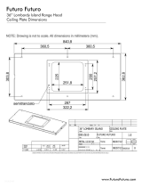
Overall Dimensions
Weight: 66 lbs. (30 kg)
Must be attached to
load-bearing component
(joist/frame/plywood),
NOT to bare sheetrock.
Stand by ON

3
min. 12”
14 3/8”
ø6”
ø
6“
4 1/4”
ø 6”
14 3/8”
11 3/4”
5/8”
General Components Location
5/8”

1
H
1
14 3/8”20 1/2”
4
ø 8 mm
V1 (x2)
S
14 3/8”
2
Ducted installation - vertical blower output
Mounting, Part I:
It is recommended for the center of the range hood
to be approximately 26” - 28” above the cooktop,
for best capture performance.
1.) Measure 20 1/2” from the cooktop to the bottom
of the hood.
2.) Remove the mounting bracket from the hood, position
it on the wall, and ensure it ’s level.
3.) Mark the location of the mounting screws. Note that
these LOAD-BEARING screws should be connected to
a stud, framework, or 3/4” plywood - NO
T to bare sheetrock.
4.) Attach the bracket to the wall.
2
1
2
3
1
C
B
3
V3 (x2)
4
2
Mounting, Part II:
1-3.) Open the bottom panel, if installed, and remove the
metal lters, if present. Locate 2 the security L-brackets
on top, unscrew & remove them.
4.) Hang the range hood on the mounting bracket,
making sure to engage BOTH mounting hooks.
5.) If adjustment is necessary, each mounting hook has
2 adjustment screws - the upper screw (B) controls
distance from wall, the lower screw (C) controls
vertical adjustment.
4

Backdraft Damper Installation
A backdraft damper is supplied with the range hood.
For DUCTED installation, it’s strongly recommended to DISCARD this damper, and use a damper built into the
end-cap (wall or roof cap).
For DUCTLESS installation: insert the damper as shown into the blower output collar
, open the blades, and secure
the damper with the provided screw
Attach the bracket to the wall.
1
2
3
M
4
ø 6”
6”
5

Ducted installation - rear (horizontal) blower output
H
1
14 3/8”20 1/2”
S
14 3/8”
A
2
B
Ø 8 mm
3
x4
4
-
Mounting, Part I:
1
It is recommended for the center of the range hood
to be approximately 26” - 28” above the cooktop,
for best capture performance.
1.) Measure 20 1/2” from the cooktop to the bottom
of the hood.
2.) Remove the mounting bracket from the hood, position
it on the wall, and ensure it ’s level.
3.) Mark the location of the mounting screws. Note that
these LOAD-BEARING screws should be connected to
a stud, framework, or 3/4” plywood - NO
T to bare sheetrock.
4.) Attach the bracket to the wall.
Mounting, Part II: Blower Removal
1-2.) Remove the indicated screws & remove bottom panel.
3-4.) Remove the indicated screws & remove top panel.
5.) Disconnect the control panel cable from blower .
6.) Disconnect the power cable from the blower
.
7.) Disconnect the grounding wire from the hood backplate.
8.) Remove the 6 screws holding the blower .
1
V7
(x6)
5
Connettore comandi
Panel control connector
2
Cavo alimentazione
Power cable
3
4
2
6

4
1
T
2
3
4a
4b
4c
5
Connettore comandi
Panel control connector
6
Cavo alimentazione
Power cable
7
8
9
10
5a
Blower Motor Repositioning
Remove the blower, remove the knock-out plate (1), and re -install the blower in new direction,
repeating the steps described on the previous page in reverse.
Ducted installation - rear (horizontal) blower output
7

1
32
Metal Mesh Filters
For ducted AND ductless installation
Carbon (charcoal) Filters
ONLY for DUCTLESS installation
8

9
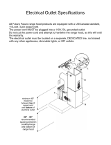
The electric circuit to which the hood is to be connected
must be:
* In compliance with local electrical standards,
* Properly grounded,
* Dedicated, not shared with other appliances or dimmable lights.

10
The duct (air pipe) must have:
* A diameter of 6” throughout its entire run, including the end-cap (roof or wall cap).
* A slight slope downward in horizontal sections - to prevent condensation from
dripping back into the blower motor.
* Minimum number of angles & elbows, to minimize turbulence and loss of suction.
* Minimum required length to avoid vibrations / turbulence, which can affect
the performance of the hood as well as user’s comfort level.
/