Page is loading ...

Z-DeckTM
Truck Leveler
Owners Manual
This Manual Covers Dock Lifts Built After Serial Numbers:
C78604 and up
PRINTED IN U.S.A.
RITE-HITE PRINT SHOP
PUBLICATION NO. 1241
MAY 2014
MADE IN U.S.A.

RITE-HITE® Z-DeckTM Truck Leveler Owners Manual
2 Pub. No. 1241 - May 2014
NOTES

RITE-HITE® Z-DeckTM Truck Leveler Owners Manual
Pub. No. 1241 - May 2014 3
TABLE OF CONTENTS
INTRODUCTION . . . . . . . . . . . . . . . . . . . . . . . . . . . . . . .3
PRODUCT SPECIFIC WARRANTY . . . . . . . . . . . . . . . . . . . . . . .3
NOTICE TO USER . . . . . . . . . . . . . . . . . . . . . . . . . . . . . .3
SAFTY WARNINGS. . . . . . . . . . . . . . . . . . . . . . . . . . . . . .4
OWNER RESPONSIBILITY . . . . . . . . . . . . . . . . . . . . . . . . . . .6
GENERAL FEATURES . . . . . . . . . . . . . . . . . . . . . . . . . . . .7
INSTALLATION INSTRUCTIONS . . . . . . . . . . . . . . . . . . . . . . . .9
OPERATION INSTRUCTIONS . . . . . . . . . . . . . . . . . . . . . . . . 12
MAINTENANCE . . . . . . . . . . . . . . . . . . . . . . . . . . . . . . 13
TROUBLESHOOTING AND ADJUSTMENTS. . . . . . . . . . . . . . . . . . . 14
HYDRAULIC SCHEMATICS . . . . . . . . . . . . . . . . . . . . . . . . . 15
ELECTRICAL SCHEMATIC . . . . . . . . . . . . . . . . . . . . . . . . . . 16
REPLACEMENT PARTS . . . . . . . . . . . . . . . . . . . . . . . . . . . 18
STANDARD WARRANTY . . . . . . . . . . . . . . . . . . . . . BACK COVER
NOTICE TO USER
Your local RITE-HITE® representative provides a Planned Maintenance Program (P.M.P.) which can be tted to your
specic operation. Call your local representative or the RITE-HITE® Corporation at 414-355-2600.
The RITE-HITE® products in this manual are covered by one or more of the following U.S. patents: 5,546,623; 5,553,987;
5,582,498; 5,664,930; 5,702,223; 5,762,459 (RE: 37,570); 5,882,167; 6,065,172; 6,070,283; 6,085,375; 6,089,544;
6,092,970; 6,106,212; 6,116,839; 6,190,109; 6,276,016; 6,311,352; 6,318,947; 6,322,310; 6,360,394; 6,368,043;
6,431,819; 6,488,464; 6,499,169; 6,505,713; 6,520,472; 6,524,053; 6,634,049; 6,726,432; 6,773,221; 6,832,403;
6,880,301; 7,032,267; 7,062,814; 7,134,159; 7,213,285; 7,216,391; 7,363,670; 7,380,305; 7,503,089; 7,533,431;
7,546,655; 7,584,517; 7,681,271; 7,823,239; 7,841,823; 7,877,831; 7,914,042; 8,006,811; 8,065,770; 8,141,189;
8,191,194; 8,286,757; 8,287,223; 8,303,235; 8,307,956; 8,443,474; 8,464,384; 8,464,846; 8,465,245 and pending U.S
and foreign patent applications. RITE-HITE®, LEVEL-RITE®, THINMANTM, SAFE-T-LIP®, HYDRACHEK®, WHEEL-LOKTM,
DOK-LOK®, DUAL-DOK®, SAFE-T-STRUTTM, DOK-COMMANDER®, JUMBOTM, HYDRA-RITETM, SAFE-T-GATE®, and
SMOOTH TRANSITION DOK SYSTEMTM, are trademarks of RITE-HITE® Corporation.
IMPORTANT
Read and understand contents of this manual prior to installation or operation of this equipment.
For best results, have this product serviced by your authorized RITE-HITE® representative.
PRODUCT SPECIFIC WARRANTY
RITE-HITE® warrants the Z-DeckTM Truck Leveler for one-year parts and labor from date of shipment in accordance with
Rite-Hite’s Standard Warranty Policy.
INTRODUCTION
The Z-DeckTM Truck Leveler is designed to provide a safer work place for workers in shipping and receiving dock areas.
The Z-DeckTM Truck Leveler is a hydraulic device that, when properly installed and operated provides safe and secure
access between truck and dock. The Z-DeckTM Truck Leveler is operated by pressing push buttons on an inside control
box.

RITE-HITE® Z-DeckTM Truck Leveler Owners Manual
4 Pub. No. 1241 - May 2014
SAFTY WARNINGS
FIGURE 1 - LOCKOUT/TAGOUT
LOCKOUT/TAGOUT PROCEDURES
The Occupational Safety and Health Administration requires that, in addition to posting safety warnings and barricading
the work area, the power supply has been locked in the OFF position or disconnected. It is mandatory that an approved
lockout device is utilized. An example of a lockout device is illustrated. The proper lockout procedure requires that the
person responsible for the repairs is the only person who has the ability to remove the lockout device.
In addition to the lockout device, it is also a requirement to tag the power control in a manner that will clearly note that
repairs are under way and state who is responsible for the lockout condition. Tagout devices have to be constructed and
printed so that exposure to weather conditions or wet and damp locations will not cause the tag to deteriorate or become
unreadable.
RITE-HITE® Corporation does not recommend any particular lockout device, but recommends the utilization of an
OSHA approved device (refer to OSHA regulation 1910.147). RITE-HITE® Corporation also recommends the review and
implementation of an entire safety program for the Control of Hazardous Energy (Lockout/Tagout). These regulations are
available through OSHA publication 3120.
This is the highest level statement. Failure to
follow the listed instructions will most likely result in
severe injury or death.
This is a statement of serious hazard. Failure
to follow the listed instructions could place the
individual at risk of serious injury or death.
The statements used with this level of
warning deal with a safe operating
procedure. If the procedure is ignored, the
possibility of personal injury may exist.
IMPORTANT is used to draw attention
to a procedure that needs to be followed to prevent
machine or property damage.
When working with electrical or electronic controls,
make sure that the power source has been locked
out and tagged according to OSHA regulations and
approved local electrical codes.

RITE-HITE® Z-DeckTM Truck Leveler Owners Manual
Pub. No. 1241 - May 2014 5
OTHER IMPORTANT SAFETY WARNINGS
• Beforestartinginstallationormaintenance,
check and follow the safety procedures of the
facility where the Z-DeckTM is being installed.
• Neverenteratruck/traileruntilitsbrakesare
set, air has been dumped from air ride
suspension (if applicable), and you have
visually inspected to be sure truck/trailer is
securely held in place by a vehicle restraint or
wheel chock per OSHA regulations.
• DONOToperatewithanyoneunderplatform
or in front of the lip.
• Keephands,limbsandloosehairclearof
equipment when operating the table. DO NOT
wear loose clothing or jewelry while operating
this equipment.
• Ifamalfunctiondoesoccur,alwayscallyour
authorized RITE-HITE® service representative
immediately.
• Postwarningsandbarricadesatdocklevel
and at drive level to indicate that work is
being done around and under the lift table.
• Inspectmonthlytoensurethatthereareno
broken or worn parts which could cause injury
to personnel or damage to the equipment.
• Lockout/Tagoutpowertothetrailerliftand
post warnings when work is being performed
on the dock lift.
• Makesurethattheliftingequipmentiscapable
of lifting 8,000lbs. or greater.
• Securelyattachliftinhchainstotheliftinglugs.

RITE-HITE® Z-DeckTM Truck Leveler Owners Manual
1. The owner should recognize the inherent danger of
the interface between dock and transport vehicle. The
owner should, therefore, train and instruct operators
in the safe use of dock equipment in accordance with
the information provided below. The manufacturer
shall publish, provide to the initial purchaser, and
make the following information readily available to
owners:
• Installationinstructions
• Recommendedinitialandperiodicinspections
procedures
• Maintenanceprocedures
• Operatinginstructions
• Descriptionsorspecicationsforreplaceableor
repairable parts
• Tablesidentifyingthegrade(slope)forall
variationsoflengthorcongurationofthedock
equipment.
• Informationidentifyingthemaximum
uncontrolled drop encountered upon sudden
removal of support while within the working range
of the equipment
Itshallbetheresponsibilityoftheownertoverifythat
the material listed in this section has been received
and that it is made available for the instruction
and training of personnel entrusted with the use or
maintenance of the dock equipment.
2. When a transport vehicle is parked at a loading
dock, it is important that the vehicle is relatively
perpendicular to the dock face and in close contact
with at least one of the dock bumpers.
3. Nameplates, cautions, instructions, and posted
warnings shall not be obscured from the view of
operating or maintenance personnel for whom such
warnings are intended.
4. Manufacturer’srecommendedperiodicmaintenance
and inspection procedures in effect at date of
shipment shall be followed, and written records of the
performance of these procedures should be kept.
5. As with any piece of machinery, dock equipment
requires routine maintenance, lubrication, and
adjustments.YourlocalRITE-HITE® representative
offersownerstheoptionofaPlannedMaintenance
Program(P.M.P.).Aspartofthisservice,yourlocal
RITE-HITE® representative will do all routine
maintenance, lubrication, and adjustments.
6. Dockequipmentthatisstructurallydamagedshall
be removed from service, inspected by a
manufacturer’sauthorizedrepresentative,and
repaired as needed before being placed back in
service.
7. The manufacturer shall make available
replacement nameplates, caution/instruction
labels, and operating/maintenance manuals upon
request of the owner. The owner shall see that all
nameplates, caution/instruction markings or labels
are in place and legible, and that the appropriate
operating/maintenance manuals are provided to
users.
8. Modicationsoralterationsofdockequipmentshall
be made only with written permission of the original
manufacturer. These changes shall also satisfy all
safety recommendations of the original equipment
manufacturer for the particular application of the dock
equipment.
9. When industrial trucks are driven on and off
transport vehicles during the loading and unloading
operation, the brakes on the transport vehicle shall
be applied and wheel chocks or a positive restraining
device shall be engaged.
10. Inselectingdockequipment,itisimportantto
consider not only present requirements but also
future plans or adverse environments.
6 Pub. No. 1241 - March 2009
OWNER RESPONSIBILITY

RITE-HITE® Z-DeckTM Truck Leveler Owners Manual
Pub. No. 1241 - May 2014 7
PLATFORM
The platform provides the lifting mechanism for the
truck/trailer. It is hinged at the front of the frame. The
platform is constructed of steel, with a non-slip coating
on the traction surfaces.
WHEEL GUIDES
The wheel guides are steel structures located in front of
the leveler platform and to the approach edges. These
guides assure the proper truck/trailer wheel alignment.
LIFTING LUGS
The lifting lugs are welded to the Z-DeckTM weldment.
These lugs are the attachment points when the unit is
lifted for installation or maintenance.
LIFTING CYLINDER AND MOUNTING PADS
The lifting cylinder is a single acting cylinder of
heavy-duty steel construction. When the power unit
is energized, the cylinder extends, lifting the platform.
When the power is removed, the unit holds position.
When the LOWER button is pressed, the platform’s
weight compresses the cylinder and returns the oil to
the reservoir, allowing the entire unit to lower to grade
level. Attached to each cylinder is a mounting pad.
When attached with the mounting bolts, the mounting
pads secure the cylinder rod end to the concrete
loading dock approach.
POWER UNIT
This assembly pumps hydraulic uid to the platform
lifting cylinders. The power unit consists of an electric
motor, a gear pump, a hydraulic uid reservoir, and
valving. The combination breather/ller cap. Hydraulic
uid can be added to the system by removing this cap
and pouring oil into the reservoir.
VELOCITY FUSE
In case of hose failure, the hydraulic truck leveler is
equipped with an emergency support system valve
called a velocity fuse. This valve is rigidly mounted to
the lifting cylinder hydraulic plumbing.
When an emergency drop occurs, the lift should be
inspected thoroughly by a RITE-HITE® representative.
If nothing has failed, normal operation can be resumed
by pressing the lift UP button to reset the velocity fuse.
DEBRIS GUARDS
The debris guards are located along both sides of
the Z-DeckTM Truck Leveler. These guards assist
in preventing debris from blowing underneath the
Z-DeckTM Truck Leveler.
CONTROL BOX ASSEMBLY
The control box for the Z-DeckTM Truck Leveler has two
buttons, RAISE and LOWER. It also includes a green
“Platform Fully Lowered” pilot light.
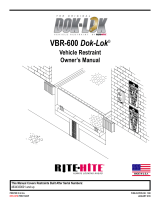
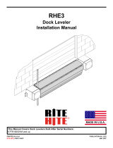
GENERAL FEATURES

RITE-HITE® Z-DeckTM Truck Leveler Owners Manual
8 Pub. No. 1241 - May 2014
DURING OPERATION PERSONNEL MUST STAY CLEAR OF SIDES OF TRUCK LEVELER AT ALL TIMES.
NEVER OPERATE THE TRUCK LEVELER WITHOUT A TRUCK/TRAILER PARKED IN POSITION.
NEVER RAISE TRUCK LEVELER UNTIL:
THE TRUCK/TRAILER BRAKES ARE SET
AIR HAS BEEN DUMPED FROM AIR RIDE SUSPENSION (IF APPLICABLE)
THE TRUCK/TRAILER HAS BEEN RESTRAINED VIA WHEEL CHOCKS OR OTHER MECHANICAL MEANS
NEVER BE UNDER THE PLATFORM OR SERVICE THE EQUIPMENT WITHOUT THE FOLLOWING:
INSERTING BOTH MAINTENANCE STRUTS AT REAR (DOCK END) OF SIDE TUBES
BARRICADING THE INSIDE AND OUTSIDE WORK AREAS.
FOLLOWING MAINTENANCE SUPPORT PROCEDURES AS SHOWN IN OWNERS MANUAL.
IF REPLACING A LIFTING CYLINDER IS REQUIRED, FOLLOW THE MAINTENANCE LIFTING PROCEDURE
AS OUTLINED IN THE OWNER'S MANUAL AND LIFT ONLY IN THE DESIGNATED SPOTS WITH
EQUIPMENT CAPABLE OF HANDLING 7,500 lb.
P/N LE 1498 REV. XX
Milwaukee, Wisconsin 53223
(800) 456-0600
PRODUCTS CORPORATION
R
TRUCK LEVELER
RAISE LOWER
PLATFORM
FULLY LOWERED
WHEN GREEN
LIGHT IS ON
IMPORTANT
ALWAYS PRESS AND HOLD THE LOWER BUTTON UNTIL
THE TRAILER IS FULLY LOWERED AND THE GREEN
“PLATFORM FULLY LOWERED” LIGHT IS ON
WARNING
WARNING
WHEN SERVICING OR REPAIRING THIS MACHINE, USER MUST LOCKOUT AND TAGOUT THE MACHINE.
COMPLY WITH OSHA 1910.147
Lifting
Lugs
Power Unit
Control Box
Wheel Guide
Wheel Guide
Lifting Lugs
Debris Guard
Debris Guard
Maintenance
Strut
Maintenance
Strut
Side Load
Brace
Side Load
Brace
Hinge Plate
Hinge Pin
Hinge Plate
Hinge Pin
Lifting Cylinder
Platform
FIGURE 2 - FEATURES

RITE-HITE® Z-DeckTM Truck Leveler Owners Manual
Pub. No. 1241 - May 2014 9
INSTALLATION INSTRUCTIONS
1. Inspect all equipment to ensure there has been no
freight damage and that all components have arrived.
NOTE: You should receive the following.
• Truck Leveler Deck (assembled with
hoses, cylinders and limit switch).
• Pallet with hydraulic power unit and control
box.
• Pallet with front base plates, wheel guides,
anchors, side load braces and side guards.
2. Review location to ensure it meets installation
needs. If there are any questions, contact RITE-HITE
Applications.
3. Review location of trench or other drains. Lifting
cylinders are located 78” from the bumper face and are
8” wide. Do not place cylinder pads directly over drains.
4. Locate the centerline of the dock. The truck leveler will
be centered on the dock position. See gure 3.
5. Place rear edge of truck leveler platform 32” off
BUMPER face. Make sure you compensate for thicker
bumper projections. See gure 4.
Example: 6” bumpers + 32” = 38” off dock face.
NOTE: Review restraint projection to ensure proper
clearances before setting truck leveler platform.
INSTALLATION INSTRUCTIONS
• Lockout/Tagoutpowertothetrailerlift
according to OSHA regulations and approved
local codes before welding on the truck leveler.
• Beforestartinginstallationormaintenance,
check and follow the safety procedures of the
facility where the Z-Deck is being installed.
• Makesurethattheliftingequipmentiscapable
of lifting 8,000lbs. or greater.
• Securelyattachliftingchainstotheliftinglugs.
A
A
CD
25'
Radius
25'
Radius
32”
C
D
BB
Dock Face
52-1/2"
C
L
52-1/2"
FIGURE 3 - DOCK CENTERLINE
32"
Off Bumper
Face
78" To Back Edge Of Base
85" To Front Of Base
FIGURE 4 - TRAILER LIFT POSITION

RITE-HITE® Z-DeckTM Truck Leveler Owners Manual
10 Pub. No. 1241 - May 2014
INSTALLATION INSTRUCTIONS - CONT.
52 1/2”52 1/2”
Centerline Of
Loading Dock
And Truck Leveler
Dock Face
32”
52 3/4” 52 3/4”
131 1/2”
105 1/2”
2”
Gap Between Deck
And Debris Guard
2”
Off
Bumper
Face
Dock Bumper
FIGURE 5 - PLATFORM POSITIONING

RITE-HITE® Z-DeckTM Truck Leveler Owners Manual
Pub. No. 1241 - May 2014 11
6. Square truck leveler platform. It is very important that
the truck leveler be square to the dock face.
7. Using lifting bar raise cylinder base plates and center
between structure channels.
8. Edge of cylinder plates must be 2” outside of lifting tube
and centered between channels.
9. If the dock is substantially canted from one side to
another, shim as required underneath base plates.
10. Bolt cylinder base plates to ground using (2ea.) 5/8” x
4” concrete anchors (Supplied).
11. Install front hinge plate weldments. Insert hingh pins
from inside of platform, so washer is on tire side of
hinge. Use washers and cotter pins supplied with pins.
12. Drill and epoxy anchor front hinge plates to the
approach in (14ea.) places with 3/4” x 6” anchors.
13 Install front wheel guides. See gure 6.
14. Install front debris guard at the back edge of the front
base plate and 2” off the side of the platform using 3/8”
stud anchors (Supplied). Align rear debris guard as
needed.
15. Install Side Load Braces at rear of platform. Review
dock side clearances if multiple units shall be installed
next to each other. Stagger placement of guards.
Each brace requires (4ea.) 5/8” x 4” concrete anchors
(Supplied).
16. Drill 3” diameter hole in wall and protect with PVC pipe
so hoses do not become damaged. Seal hole with
expandable foam after installation.
17. Place power unit inside building under control box. Bolt
down to keep from moving.
NOTE: Power unit must be protected via steel bollard
or other means to prevent damage.
18. Connect the two hydraulic hoses to the ttings on the
power unit.
NOTE: Power unit and hoses have been completely
lled and purged of air at the factory. Some leakage
may occur during connection of hoses; however there
is an adequate amount of uid in the reservoir tank in
case of minor spillage.
19. Locate and install the control boxes on wall adjacent
to the overhead door at approximately 48” above the
oor level. Secure control box to wall in accordance
with all local and national electrical codes. Nails are not
acceptable.
20. Connect control box to incoming power using Electrical
Schematics (shipped inside control boxes) and Wiring
Diagram.
NOTE: Fused disconnect must be provided within
sight of control box. This is the responsibility of the
electrician and the owner.
21. Installation complete. Test unit by following the
Operation Instructions in this manual.
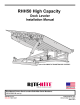
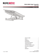
INSTALLATION INSTRUCTIONS - CONT.
52 1/2”52 1/2”
Centerline Of
Loading Dock
And Truck Leveler
Dock Face
32”
52 3/4” 52 3/4”
131 1/2”
105 1/2”
2”
Gap Between Deck
And Debris Guard
2”
Off
Bumper
Face
Dock Bumper
FIGURE 6 - WHEEL GUIDE PLACEMENT
Top View
FIGURE 7 - SIDE LOAD BRACE PLACEMENT

RITE-HITE® Z-DeckTM Truck Leveler Owners Manual
12 Pub. No. 1241 - May 2014
OPERATING INSTRUCTIONS
1. No trailer at dock, inside green light is ON signaling the
truck leveler is completly lowered.
2. Restrain trailer via wheel chocks or mechanical means.
3. Open door.
4. Lift trailer bed to desired level by pressing and holding
the RAISE TRAILER pushbutton
5. Once loading is complete, store dock leveler.
6. Press and hold the LOWER TRAILER pushbutton until
unit is completely stored at grade level and the inside
green light is ON.
7. Close door.
8. Release trailer.
OPERATION INSTRUCTIONS
Read and obey these instructions to prevent
personal injury.
• DONOToperatetheliftuntiltruck/traileris
parked against the dock bumpers and the
truck/ trailer has been secured.
• ALWAYSsecureloadwhenusingthedocklift.
• NEVERenteratruck/traileruntilitsbrakes
are set, air has been dumped from the air
ride suspension (if applicable), and you have
visually inspected truck/trailer to ensure
truck/trailer is securely held in place
by a vehicle restraint or wheel chocks
per OSHA regulations.
• NEVERreleasethevehiclerestraintor
remove the wheel chocks until loading/
unloadingisnishedandthetruckdriverhas
been given permission to drive away from the
dock.
FIGURE 8 - TRAILER PARKED AT DOCK
DURING OPERATION PERSONNEL MUST STAY CLEAR OF SIDES OF TRUCK LEVELER AT ALL TIMES.
NEVER OPERATE THE TRUCK LEVELER WITHOUT A TRUCK/TRAILER PA RKED IN POSITION.
NEVER RAISE TRUCK LEVELER UNTIL:
THE TRUCK/TRAILER BRAKES ARE SET
AIR HAS BEEN DUMPED FROM AIR RIDE SUSPENSION (IF APPLICABLE)
THE TRUCK/TRAILER HAS BEEN RESTRAINED VIA WHEEL CHOCKS OR OTHER MECHANICAL MEANS
NEVER BE UNDER THE PLATFORM OR SERVICE THE EQUIPMENT WITHOUT THE FOLLOWING:
INSERTING BOTH MAINTENANCE STRUTS AT REAR (DOCK END) OF SIDE TUBES
BARRICADING THE INSIDE AND OUTSIDE WORK AREAS.
FOLLOWING MAINTENANCE SUPPORT PROCEDURES AS SHOWN IN OWNERS MANUAL.
IF REPLACING A LIFTING CYLINDER IS REQUIRED, FOLLOW THE MAINTENANCE LIFTING PROCEDURE
AS OUTLINED IN THE OWNER'S MANUAL AND LIFT ONLY IN THE DESIGNATED SPOTS WITH
EQUIPMENT CAPABLE OF HANDLING 7,500 lb.
P/N LE 1498 REV. XX
Milwaukee, Wisconsin 53223
(800) 456-0600
PRODUCTS CORPORATION
R
TRUCK LEVELER
RAISE LOWER
PLATFORM
FULLY LOWERED
WHEN GREEN
LIGHT IS ON
IMPORTANT
ALWAYS PRESS AND HOLD THE LOWER BUTTON UNTIL
THE TRAILER IS FULLY LOWERED AND THE GREEN
“PLATFORM FULLY LOWERED” LIGHT IS ON
WARNING
WARNING
WHEN SERVICING OR REPAIRING THIS MACHINE, USER MUST LOCKOUT AND TAGOUT THE MACHINE.
COMPLY WITH OSHA 1910.147
Truck leveler MUST BE stored in the completely
lowered position to avoid damage to the building and/
or equipment as new trailers back in to the dock.
FIGURE 9 - CONTROL BOX

RITE-HITE® Z-DeckTM Truck Leveler Owners Manual
Pub. No. 1241 - May 2014 13
SUGGESTED TRUCK LEVELER
MAINTENANCE
NOTE: Follow maintenance procedures below as
outlined. Include the specic steps for your
leveler model.
NOTE: Your local RITE-HITE® representative provides
a Planned Maintenance Program (P.M.P.)
which can be tted to your specic operation.
Call your local representative.
DAILY
1. During normal operation, inspect and report any
damaged parts or erratic operation. If there are any
broken or worn parts repair as needed.
2. Clean large debris or ice build-up from the dock area.
90 DAYS
1. Preform all Daily Maintenance.
2. Grease front hinge points.
3. Oil cylinder base pins.
4. Check uid level. If unit is low of uid, rell and inspect
hoses and ttings for damage or leaks.
5. Check condition of oil lter on the power unit by looking
at the lter manifold eye. If the eye is green, the lter is
good. If the eye is red, replace the lter.
6. Check to make sure that the debris guards are not
damaged or missing and inspect unit for any stuctural
damage.
7. Check the wheel guides for damage. Retorque any
loose mounting bolts.
8. Check UHMW wear pads on Side Load Braces.
MAINTENANCE
Post safety warnings and barricade work area,
at dock level and at ground level, to prevent
unauthorized use of the dock position.
Lockout/Tagout power to the trailer lift according to
OSHA regulations and approved local codes before
welding on the truck leveler.
Maintenance may be required more frequently at
loading docks exposed to harsh environments
(extreme climates, corrosive chemicals, frequency
of usage exceeding 8 trucks per day, ect.). Consult
RITE-HITE® if these conditions exist for accelerated
maintenance requirements.
All Pins -
Use SAE 30 Oil
UHMW Wear Pad UHMW Wear Pad
FIGURE 10 - LUBRICATION

RITE-HITE® Z-DeckTM Truck Leveler Owners Manual
14 Pub. No. 1241 - May 2014
FLOW CONTROL ADJUSTMENT
Thisadjustmenttobeperformedbyaqualied
technician only. Refer to gure 5.
For adjustment, rst unlock the outside locknut.
(Adjustments should be made in 1/4 turn increments)
• To decrease platform fall speed turn adjustment screw
clockwise.
• To increase platform fall speed turn adjustment screw
counterclockwise.
NOTE: When making adjustments in extremely cold
temperatures (below freezing), run unit
several times to conrm that the velocity fuse
doesn’t lock-up with warmer oil.
TROUBLESHOOTING AND ADJUSTMENTS
Symptom Probable Cause Remedy
1. Platform does not lift. a. Excessive load. a. Remove load
b. Fuse and/or overload blown. b. Check fuse and/or overload reset.
c. Low oil level and/or oil leak. c. Check oil level. Check for leaks
that may have caused low oil level.
d. Defective pump. d. check system pressure. If pres
sure is too low may be worn out
pump. Replace if necessary.
e. Defective valve. e. Check valve block. Repair/Replace
if necessary.
f. Filter is clogged. f. Clean or replace suction lter.
2. Platform does not a. Oil Leak. a. Repair oil leaks.
maintain steady height. b. Defective check valve. b. Replace check valve.
c. Defective solenoid valve. c. Replace solenoid valve.
3. Platform locked in “UP” a. Velocity fuse locked up due to air. a. Cycle unit (5 to 10 times) until
position. velocity fuse no longer locks up.
b. Velocity fuse locks up due to b. See Adjustments.
valve adjustment.
(unit lowering to fast)
c. Bent safety stop bar. c. Replace safety stop bar.
Locknut
Adjustment
Screw
O-Ring
FIGURE 11 - FLOW CONTROL ADJUSTMENT

RITE-HITE® Z-DeckTM Truck Leveler Owners Manual
Pub. No. 1241 - May 2014 15
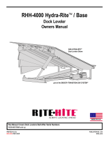
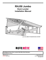
HYDRAULIC SCHEMATICS
POWER UNIT
MESH
FILTER
2100 PSI MAX
@5 GPM RELIEF VALVE
ADJUSTABLE
PRESURE
COMPENSATED FLOW
CONTROL
2-WAY 2-POSITION
SOLENOID VALVE
120V/1PH COILS
WITH MANUAL
OVERRIDE
PULL TO RELEASE
0-3000 PSI GLYCERIN GAGE AND SHUT OFF
WITH MANUAL 2 WAY SOLENOID OVERRIDE AND EXTRA TANK
LINE TEE PORT INSTALLED
5 HP- 1750 RPM - TEFC motor
4.11GPM 24 SECONDS TO FULL RAISE
2100 PSI ADJUSTABLE RELIEF
460V/230V -3PH
FLA 6.6 / 13.2 respectively
184 TC Frame
CHECK VALVE
PRESSURE
GAUGE
4" BORE x 2" ROD - 16" STROKE CYLINDERS
PORTS-SAE
#8 ORB
DRILL 3" DIAMETER HOLE IN BUILDING WALL
USE PVC SLEEVE TO PROTECT HOSES
FIGURE 12 - HYDRAULIC SCHEMATIC - STANDARD

RITE-HITE® Z-DeckTM Truck Leveler Owners Manual
16 Pub. No. 1241 - May 2014
ELECTRICAL SCHEMATIC
Copper Wire
75°C Minimum
NOTE:
FIELD SUPPLIED BRANCH CIRCUIT PROTECTION OF 25 AMP
MAXIMUM AND DISCONNECTING MEANS REQUIRED
TO MEET N.E.C. AND LOCAL CODES.
Copper Wire
75°C Minimum
102
L2
L3
L1
101
1L2 1L3
N
22
21
20
19
18
17
16
15
6
14
13
12
11
10
9
8
7
5
4
3
2
1
DEVICE LOCATED IN THE FIELD
TERMINAL IN CONTROL PANEL
INDICATES FIELD WIRING
LOCATION CODE:
(F)
LEVELER RELAY
119, 121
LEVELER STORED
RAISE MOTOR
102, 115
2L3
2L1
2L2
L2 L3
105
SPARE
107
108
109
110N
102
NLOWER VALVE
103
106
103A 104
FU1
FNQ-R1
M1
M1
CR1
5 9
MMP1
CR1
13 14
PL1
G
MMP1
RAISE
MOTOR
6.6 FLA
460/3
5
(F)
SV1
(F)
M1
CR1
8 12
LS2
(F)
T1
0.100KVA
240V
115V
FU2
FRN-R-1.25
LS1
(F)
PB2
LOWER
12 AWG
16 AWG (TYP. )
(F)
GND LUG
Minimum 10 AWG
75°C, Copper
12 AWG
HP
SET O.L. TO MOTOR
NAMEPLATE FLA
(FACTORY SET @ 6.6A)
H4
H3 H2
X2
X1
H1
NOTE:
REMOVE JUMPER IF LS1
(LOK UPPER TRAVEL) IS USED
SHOWN AT 240 VOLT 3PH
NEED STANDARD 480 VOLT 3 PHASE
FUSES AND TRANSFORMERS
SHOWN AT 240 VOLT 3PH
NEED STANDARD 480 VOLT 3 PHASE
FLA = 6.6 AMP AT 460 3
FLA = 13.2 AMP AT 230 3
240 VAC
60 HZ.
3 PH
15.7 FLA
PB1
RAISE
FIGURE 13 - ELECTRICAL SCHEMATIC - STANDARD

RITE-HITE® Z-DeckTM Truck Leveler Owners Manual
Pub. No. 1241 - May 2014 17
NOTES

RITE-HITE® Z-DeckTM Truck Leveler Owners Manual
18 Pub. No. 1241 - May 2014
REPLACEMENT PARTS
1
2
3
4
5
6
7
5
6
7
8
9,10
PLATFORM ASSEMBLY
Item Qty Description RH Part Number Leum Part Number
1 1 Platform Weldment Z-Deck 145523 LE 937
2 2 Side Load Brace 145524 LE 604
3 1 RH Side Back Debris Guard 145525 LE 609-2
3 LH Side Back Debris Guard (Not Shown) 145526 LE 609-1
4 1 RH Side Front Debris Guard 145527 LE 609-4
1 LH Side Front Debris Guard (Not Shown) 145528 LE 609-3
5 2 Hinge Pin 145529 LE 1328
6 2 Hinge Plate 145530 LE 325
7 2 Wheel Guide 102461 -
8 2 Maintenance Strut 145531 LE 1329
9 1 Limit Switch 102500 -
10 1 Limit Switch Mounting Bracket 145532 LE 610

RITE-HITE® Z-DeckTM Truck Leveler Owners Manual
Pub. No. 1241 - May 2014 19
7
1
2
9
10
6
10
6
2
Hydraulic Power Unit
5
3
12
11
14
12
11
15
15
8
8
13
“P” Port
“R” Port
Runs Through Platform
Structure Channel
4
HYDRAULIC REPLACEMENT PARTS
* Specify Hose Lenght If Greater Than 20 Feet.
Item Qty Description RH Part Number Leum Part Number
1 1 Hose Assy .50ID 150L 10FJS 6FJS 3000PSI 145511 LE 2856
2 2 Hose Assy .38ID 47L 6FJS 8FJS 90 DEG 3000PSI 145512 LE 2862
3 1 Hose Assy .38ID 125L 6-6FJS Elb 90 DEG 0 DEG 3000PSI 145513 LE 2859
4 1 Hose Assy .25ID 150L 4-4FJS 3000PSI 140898 LE 2863
5 1 Hose Assy .25ID 125L 4-4FJS Elb 90 DEG 0 DEG 3000PSI 145514 LE 2858
6 2 Hose Assy .25ID 35L 4-4FJS 3000PSI 145515 LE 2860
7 1 FTG ELB 90 10 MAORB 10MJ STL ZP 117646 LE 2855
8 2 Velocity Fuse 102493 -
9 1 FTG ELB 90 8MAORB 4MJ STL ZP 145516 LE 2864
10 2 FTG STRT 8MORB 4MJ STL ZP 140950 LE 2861
11 2 FTG Tee 6-6-6MJ STL ZP 55284 LE 2857
12 2 FTG Tee 4-4-4MJ STL ZP 16925 LE 2865
13 1 FTG Cap 6FJ STL ZP 103321 LE 2868
14 2 FTG Cap 4FJ STL ZP 118656 LE 2869
15 2 Hydraulic Cylinder 4 x 16 Z-Deck 141272 LE 1325

RITE-HITE® Z-DeckTM Truck Leveler Owners Manual
20 Pub. No. 1241 - May 2014
HYDRAULIC POWER UNIT REPLACEMENT PARTS
Item Qty Description RH Part Number Leum Part Number
1 1 Hydraulic Power Unit - Complete LE 1077
2 1 Wiring Harness - Hirschmann Connector 111729
3 1 Cartridge Valve - Directional 116789
1 Solenoid Valve w/manual adjust 103983
4 1 Coil Solenoid Hirschmann 104025
5 1 Gauge 103987
6 2 Manifold Assembly
7 1 Filter Element 116800
8 1 Relief Valve 116797
9 1 Pilot to Open Check Valve 116799
10 1 Breather Cap 116805
11 1 Drain Plug 116806
1
2
3
4
5
6
7
8
11
/