Page is loading ...

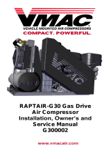
RAPTAIR-G30 Gas Drive
Air Compressor
Installation, Owner’s and
Service Manual


VMAC – Vehicle Mounted Air Compressors
Toll Free: 1-888-241-2289
Fax: 1-250-740-3201
1
RAPTAIR-G30 Gas Drive Air Compressor
Installation, Owners and Service Manual
General Information .......................................................................... 4
Read this ....................................................................................... 4
Limited Lifetime Warranty .............................................................. 4
Warranty Registration .................................................................... 4
Important Safety Notice ................................................................. 5
Safety Messages ........................................................................... 5
Safety Precautions ............................................................................ 6
Safety Features ................................................................................. 10
Gas Drive Safety Components ...................................................... 10
Automatic Overheat Shutdown ...................................................... 10
Operating Principles ......................................................................... 11
Extreme Climates and Elevation ..................................................... 13
Cold Environment Operation ......................................................... 13
Hot Environment Operation ........................................................... 14
High Altitude operation .................................................................. 14
Serial Number .................................................................................... 15
System Overview .............................................................................. 16
System Controls ............................................................................... 17
Installation Requirements ................................................................ 19
Ventilation Requirements ................................................................. 20
Mounting Locations .......................................................................... 21
Top Mounting ................................................................................. 21
Enclosed Mounting ........................................................................ 21
Mounting the Compressor ............................................................... 22
External dimensions with the base plate ....................................... 22
Mounting with the base plate ......................................................... 23
Mounting without the base plate .................................................... 24
System Hoses ................................................................................... 25
Electrical Connections ..................................................................... 26
External Electrical Connections ..................................................... 26
Battery relocation ........................................................................... 26
Key switch relocation ..................................................................... 26
Electronic Fuel Pump .................................................................... 26
Before Starting the Compressor ..................................................... 27
Starting and Stopping the Gas Drive .............................................. 29
Starting the Gas Drive with the Key Switch ................................... 29
Starting the Gas Drive with the Pull Start ...................................... 30
Stopping the Gas Drive ................................................................. 32
Setup, Performance Testing and Adjustments .............................. 33
Adjusting the Regulator (Air Pressure) .......................................... 34
Engine rpm Adjustment ................................................................. 35

VMAC – Vehicle Mounted Air Compressors
Toll Free: 1-888-241-2289
Fax: 1-250-740-3201
2
Recommended Accessories ............................................................ 36
Air Receiver Tank ............................................................................. 37
Accessory Products from VMAC .................................................... 38
Maintenance Information ................................................................. 41
Routine Maintenance .................................................................... 41
Torque Specifications .................................................................... 41
Maintenance and Repair Safety .................................................... 42
Maintenance Schedule .................................................................. 44
Inspecting and adding Compressor Oil ......................................... 45
Inspecting the Drive Belt ............................................................... 46
Inspecting the Blowdown Muffler ................................................... 47
Inspecting the Pressure Relief Valve ............................................ 48
Replacing the Compressor Air Filter ............................................. 49
Replacing the Compressor Oil Filter ............................................. 50
Changing the Compressor Oil ....................................................... 52
Changing the Compressor Coalescing Filter ................................. 54
Engine Maintenance Schedule ...................................................... 55
Spark Arrester ............................................................................... 55
Changing the Engine Air Filter ...................................................... 56
Changing the Engine Oil ............................................................... 57
Adding Engine Oil .......................................................................... 57
Problem Diagnostics ........................................................................ 58
Mechanical Components and Testing ............................................ 64
Compressor Regulator and Throttle Actuator Testing ................. 65
Electrical Components and Testing ................................................ 71
Repair Instructions ........................................................................... 75
Service Records ................................................................................ 84
Repair Records ................................................................................. 89
Warranty Registration ...................................................................... 93
KEEP THIS MANUAL WITH THE GAS
DRIVE ROTARY SCREW COMPRESSOR
UNIT FOR USER REFERENCE

VMAC – Vehicle Mounted Air Compressors
Toll Free: 1-888-241-2289
Fax: 1-250-740-3201
3
Raptair-G30 Gas Drive Air Compressor
Installation, Owners and Service Manual
System: G300001
Document #1930267
Changes and Revisions
Important Information
The information in this manual is intended for certified VMAC installers
who have been trained in installation procedures and for people with
mechanical trade certification who have the tools and equipment to
properly and safely perform the installation. Do not attempt this
installation if you do not have the appropriate mechanical training,
knowledge and experience.
Follow all safety precautions for mechanical work. Any grinding, bending
or restructuring operations for correct fit in modified trucks must follow
standard shop practices.
Notice
Manuals are subject to change without notice.
Registered Trademarks
All trademarks mentioned in this manual are the property of their
respective owners. Their use by VMAC is for identification of the
manufacturers’ products only and does not imply any affiliation or
endorsement by said companies.
Loctite® , Loctite® Klean N’ Prime™, Loctite® 242 and Loctite PST®
are registered trademarks of Henkel AG & Company KGaA.
Subaru® is a registered trademark of Fuji Heavy Industries Ltd.
Copyright 2016
All trademarks used in this manual are the property of the respective copyright holder.
The contents of this manual may not be reproduced in any form without the express
written permission of VMAC, 1333 Kipp Road, Nanaimo, BC V9X 1R3.
Printed in Canada
Revision
Revision Details
Revised
by
Checked by
Implemented
Eng.
Tech.
Qual.
Mech.
Elec.
A
Engineering Release
REF
NAC
N/A
RJD
N/A
8 Oct 2015
B
ECN 16-036 Engine shroud added
MSP
JKR
AJH
GB
AMG
13 Jun 2016

VMAC – Vehicle Mounted Air Compressors
Toll Free: 1-888-241-2289
Fax: 1-250-740-3201
4
General Information
Read this
Read this manual as well as the “Subaru Engine Manual” before
beginning the installation, or operating the system so that you can
understand the requirements. This will ensure the successful installation
and proper operation of the Gas Drive Rotary Screw Compressor.
This manual provides maintenance, repair and troubleshooting
instructions for the Gas Drive Rotary Screw Compressor system. Proper
and regular servicing provides continued high performance and long life.
Limited Lifetime Warranty
The Compressor Assembly (excluding Inlet and Clutch, where
applicable) is warranted against manufacturer defects in materials and
workmanship for the lifetime of the Compressor Assembly. Restrictions
apply – refer to VMAC Warranty Policy and VMAC Limited Lifetime
Warranty for full details.
http://vmacair.com/support/warranty/
Warranty Registration
The VMAC warranty form is located at the back of this manual. This
warranty form must be completed and sent to VMAC at the time of
installation for any subsequent warranty claim to be considered valid.
There are 4 ways warranty forms can be submitted to VMAC:
Online
http://vmacair.com/support/warranty/
Email
Fax
1-(250) 740-3202
Mail
VMAC - Vehicle Mounted Air Compressors
1333 Kipp Road, Nanaimo, BC, Canada V9X 1R3

VMAC – Vehicle Mounted Air Compressors
Toll Free: 1-888-241-2289
Fax: 1-250-740-3201
5
Important Safety Notice
The information contained in this manual is based on sound engineering
principles, research, extensive field experience and technical
information. Information is constantly changing with the addition of new
models, assemblies and service techniques. If a discrepancy is noted in
this manual, contact VMAC prior to initiating or proceeding with
installation, service or repair. Current information may clarify the issue.
Any person with knowledge of such discrepancies who performs service
and/or repair, assumes all risks.
Only proven service procedures are recommended. Anyone who departs
from the specific instructions provided in this manual must first assure
that their safety and that of others is not being compromised and that
there will be no adverse effects on performance or the operational safety
of the equipment.
VMAC will not be held responsible for any liability, consequential
damages, injuries, loss or damage to individuals or to equipment as a
result of the failure of any person to properly adhere to the procedures
set out in this manual or standard safety practices. Safety should be the
first consideration when performing service operations. If you have any
questions concerning the procedures in this manual or require any more
information on details that are not included in this manual, please
contact VMAC before beginning repairs.
Safety Messages
This manual contains various warnings, cautions and notices that must
be observed to reduce the risk of personal injury during installation,
service or repair and the possibility that improper installation, service or
repair may damage the equipment or render it unsafe.
This symbol is used to call your attention to instructions
concerning your personal safety. Watch for this symbol, it points
out important safety precautions, it means, “Attention, be alert!
Your personal safety is involved”. Read the message that
follows and be alert to the possibility of personal injury or death.
While it is impossible to warn about every conceivable hazard,
let good common sense be your guide.
This symbol is used to call your attention to instructions on a
specific procedure that if not followed may damage or reduce
the useful life of the compressor.
This symbol is used to call your attention to additional
instructions or special emphasis on a specific procedure.

VMAC – Vehicle Mounted Air Compressors
Toll Free: 1-888-241-2289
Fax: 1-250-740-3201
6
Safety Precautions
Warning
Breathing gasoline engine exhaust and gasoline vapors
can expose you to chemicals known to the State of
California to cause cancer and birth defects or other
reproductive harm.
Always start and operate the engine in a well-
ventilated area.
If in an enclosed area, vent the exhaust to the
outside.
Do not modify or tamper with the exhaust system.
Personal Safety
Do not breathe the compressor air. Vaporized oil is
a respiratory hazard.
Do not breathe engine exhaust, gasoline engines
produce carbon monoxide, a poisonous odorless
gas which can cause death. Do not start or operate
this compressor in an enclosed area.
Always use the appropriate personal protective
equipment, particularly eye and hearing protection
when operating air-powered equipment.
Fire and Explosion Hazard
Vaporized oil propelled by high-pressure air is an
explosive mixture.
Fire in the compressor can cause an explosion and
flame projection. Should this occur, there is
potential for serious injury or death.
Operate compressor in a well ventilated area free
of flammable vapors, dust, or other combustible
materials.
Do not fill the fuel tank while the system is running
or hot.
Do not refuel in an enclosed space or area with
poor ventilation.
If fuel is spilled clean area and wait for it to dry
before starting the engine.
Never place objects against or on top of the
compressor.
Never expose the tank or compressor to extreme
heat.

VMAC – Vehicle Mounted Air Compressors
Toll Free: 1-888-241-2289
Fax: 1-250-740-3201
7
Compressor Air and Oil Hazard
The compressor system is under sufficient
pressure that a leak could force the air/oil mixture
through the skin directly into your bloodstream.
This could cause serious injury or death.
Ensure the system is completely depressurized
before attempting maintenance or repair.
Do not use compressor air to clean off clothing or
skin, compressed air can penetrate the skin
causing serious injury or death.
Do not move or service the compressor while it is
pressurized or operating.
Do not move the compressor by pulling on any
hoses.
Components and hoses under pressure could
separate suddenly, fly out and cause serious injury
or death. If equipped, the receiver air tank must be
drained before servicing any components in the
compressor system.
Never adjust or attempt to make any repairs to the
system while the engine is running. Components
and hoses under pressure could fail and cause
serious injury or death.
Burst Hazard
Serious injury or death may result from an air tank
explosion.
Never exceed manufacturer’s maximum air
pressure rating.
Do not repair components, only replace with
approved parts.
Do not tamper with or disable factory safety
equipment.
Burn Hazard
The engine, exhaust and the compressor system
get very hot during operation, contact with the
components or the oil can cause serious injury.
Allow sufficient time for the system to cool before
performing service.
Never allow any part of your body to contact the
engine or compressor components.

VMAC – Vehicle Mounted Air Compressors
Toll Free: 1-888-241-2289
Fax: 1-250-740-3201
8
Lead Acid Battery Hazard
Working near Lead-acid batteries is dangerous.
Batteries may generate sulphuric acid and explosive
gasses during regular operation. Lead-acid batteries
may explode if exposed to a spark.
Follow all safety precautions when jump starting or
charging a battery.
Never attempt to jump-start a frozen battery.
Never over-charge a battery.
Moving Parts Hazard
Before performing service, disconnect the battery
and disconnect the spark plug wire to prevent
unexpected engine start.
Do not operate the compressor without guards in
place. If the guards are damaged or missing,
replace them before operating the equipment.
General Warnings
Disconnect Spark plug wire before attempting any
repair or service.
Be attentive for unexplained changes in operation
parameters and record any changes.
Check compressor oil level and condition before
starting the system. Do not add or change oil while
the system is running. Use only approved oil.
The compressor operates anytime the engine is
running. Avoid contact with the compressor, hoses,
or engine during operation.
Keep hoses and wiring away from sharp edges or
moving components.
Use only approved hoses and replacement parts.
Do not modify the equipment.
Do not operate the air compressor when fatigued or
under the influence of alcohol or drugs.
Know how to operate the compressor, fully read the
manual.
Check equipment before every use.
Never bypass or disable any of the safety
equipment.
Never adjust or attempt to make any repairs to the
compressor system while the engine is running.
Components and hoses under pressure could fail
and cause serious injury or death.

VMAC – Vehicle Mounted Air Compressors
Toll Free: 1-888-241-2289
Fax: 1-250-740-3201
9
Be aware that it is impossible to warn of all the possible
hazardous consequences that might result from
operating or servicing this system. You must use your
own judgement.
Read this information before operating the compressor for the first time.
Follow the information and procedures in this manual for operation,
maintenance and repair. Observe the following items to reduce the
chance of personal injury or equipment damage.
Follow all safety precautions for mechanical work. Moving belts and
rotating components are an extreme hazard. Stay clear of all moving
parts when the system is operating. Only qualified personnel should
perform maintenance and repair on system components and only while
the system is properly shut down.
Proper service and repair are important to the safety of the service
technician and the safe, reliable operation of the equipment. Always use
genuine VMAC replacement parts; do not use any substitutes.
The procedures described in this service manual are effective methods
of service and repair. Some procedures may require the use of tools
specially designed for a specific purpose. Anyone using a replacement
part, service procedure or tool must first determine that neither their
safety nor the safe operation of the equipment will be compromised by
the replacement part, service procedure or tool selected.

VMAC – Vehicle Mounted Air Compressors
Toll Free: 1-888-241-2289
Fax: 1-250-740-3201
10
Safety Features
Do not disable or bypass any safety components,
disabling or bypassing safety components could
result in equipment damage, injury or death.
Gas Drive Safety Components
200 psi pressure relief valve in separation manifold.
Blow-down valve to discharge system pressure on shutdown.
Temperature safety switch in compressor oil cooler.
A 15A fuse protects the electrical system.
Figure 1 – Safety components (Shroud removed for clarity)
Automatic Overheat Shutdown
If the compressor oil temperature exceeds 140 °C (290 °F), the
thermostatic switch will disable the engine, the cooling fan will remain
running as long as the key switch is in the “On” position.
The engine will not be able to be restarted until the system
has cooled and the temperature switch has closed.

VMAC – Vehicle Mounted Air Compressors
Toll Free: 1-888-241-2289
Fax: 1-250-740-3201
11
Operating Principles
Air Compression
The Gas Drive uses a VMAC designed and manufactured flooded-lobe,
rotary screw compressor. The oil-filled compressor housing contains
two rotors. Compression occurs when inlet air (at normal atmospheric
pressure) enters a chamber where it is trapped between meshing rotor
lobes. Cooled oil is injected into the rotors during compression to
lubricate the rotors and bearings, absorb the heat of compression, and
seal the rotor lobes to allow for efficient compression. As the rotors
rotate, the meshing lobes compress the volume of the trapped air/oil
mixture before sending it down the discharge line to be cooled and
separated by the WHASP tank.
Oil Separation and Cooling
The system uses a WHASP (Waste Heat Air Separation Package) tank
combined 2-stage air/oil separator and oil cooler. The hot air/oil mixture
from the compressor enters the cooler on the top of the tank, where the
mixture is cooled, the majority of the oil separates from the air (first
stage separation), and settles into the reservoir tank below the cooler.
The cooled oil then passes through a high-pressure oil filter before being
returned to the compressor via the oil return line. The remaining oil mist
and fine droplets are removed from the air by passing the air through a
coalescing filter (second stage separation). Oil removed by the
coalescing filter is collected and returned to the compressor via the 1/4”
scavenge tube.
A liquid-to-air cooler with electric fan maintains operating temperatures
which increases system durability and reduces the temperature of the
compressed air.
Minimum Pressure Check Valve
The WHASP tank has a built-in minimum pressure check valve (MPCV)
to maintain a minimum pressure of approximately 60 psi (410 kPa) in the
WHASP tank. This ensures compressor lubrication and cooling, as well
as oil separation in the coalescing filter. Air will not flow out of the
WHASP tank until around 60 psi of air pressure is reached. The MPCV
is factory set and requires no adjustment or servicing.
No separate check valve is required or recommended when connecting
the WHASP tank output to a receiver tank.

VMAC – Vehicle Mounted Air Compressors
Toll Free: 1-888-241-2289
Fax: 1-250-740-3201
12
Filtration
VMAC rotary screw compressors are designed and machined to
exacting tolerances. Foreign particles entering the compressor can
damage system components such as seals, bearings, rotors, and the
inside of the housing resulting in efficiency and performance losses and
reduced system life expectancy.
The system is equipped with a replaceable paper element air inlet filter,
spin-on high pressure oil filter and a spin-on coalescing filter.
These system filters enhance performance and extend component life
by reducing damage from dust and other debris. Proper maintenance is
the key to long compressor system life.
Compressor Drive, Belt and Tensioning
The compressor is directly driven by a six rib belt, anytime the engine is
running the compressor is running. The system has an automatic belt
tensioner (no adjustment is required).
Pressure Regulation
Pressure regulation is achieved with a mechanical regulator. The system
pressure is factory set at 150 psi. To reduce the pressure, refer to
section: “Setup, Performance Testing, and Adjustments.” Use a Filter
Regulator Lubricator (FRL) to set the final tool pressure.
Engine Speed Control
The engine speed is controlled mechanically by a pneumatic throttle,
which raises and lowers engine rpm according to air demand. No
operator input is required on the throttle lever.
Spark Arrester
The gas drive is equipped from the factory with a spark arrester.
For more information regarding the spark arrester refer to the “Subaru
Engine Manual" supplied with the system (VMAC part number:
1901022).

VMAC – Vehicle Mounted Air Compressors
Toll Free: 1-888-241-2289
Fax: 1-250-740-3201
13
Extreme Climates and Elevation
The Gas Drive has been designed to operate in
moderate climates of 0 °C to +35 °C (32 °F to +90 °F)
and at elevations below 2500 feet. Operating outside of
this range can result in performance issues with the
engine and compressor.
Cold Environment Operation
The Gas Drive compressor system is not designed or
recommended for use in cold climates (below 0 °C (32 °F)).
For operating in temperatures below 0 °C (32 °F) ensure the choke is
used during start up and the system is warmed up before air use is
started.
Cold Environment Recommendations
If operating the system below 0 °C (32 °F) ambient temperature, ensure
the following conditions are met before starting the compressor:
Use the pull-choke in cold environments, or for first start of the
engine.
Compressor system components must all be at or above 0 °C
(32 °F). Starting the system while any of the components are
below 0 °C (32 °F) may damage the compressor. Storing the
system indoors, and starting it while the components are still
warm is the only possible solution.
For engine oil recommendations in temperatures below 0 °C
(32 °F) refer to the “Subaru Engine Manual” supplied with the
system. (VMAC part number: 1901022). Not following the
Subaru Engine manual supplied can result in poor engine
performance or engine damage.

VMAC – Vehicle Mounted Air Compressors
Toll Free: 1-888-241-2289
Fax: 1-250-740-3201
14
Hot Environment Operation
For operating in temperatures above 35 °C (90 °F) compressor use may
be limited. As the Gas Drive is a 100% duty cycle compressor high
ambient air temperatures may result in compressor overheat.
The compressor system is protected by a compressor oil temperature
switch that opens at 143 °C (290 °F) and disables the engine. The
cooling fan will operate anytime the key switch is in the run position.
If the gas drive shuts off due to overheat allow the system to cool before
restarting.
For engine oil recommendations in temperatures above 35 °C (90 °F)
refer to the “Subaru Engine Manual” supplied with the system. (VMAC
part number: 1901022). Not following the “Subaru Engine Manual"
supplied can result in poor engine performance or engine damage.
Hot Environment Recommendations:
Adequate supply of cool ambient air to the unit.
Exhaust and hot air can vent from the system with no
restrictions.
WHASP radiator fins and engine recoil start are clear of debris.
Install an external fan to direct cool air towards the engine and
air compressor.
Engine and compressor serviced at correct intervals.
In certain situations, a receiver tank can help prevent
overheating issues, by lowering the duty cycle of the
compressor.
High Altitude operation
The Gas Drive has been designed to operate from 0 to 2500 feet above
sea level. Operation at high altitude may limit the compressor output and
may cause the engine to stall.
For operation above 2500 feet lowering the compressor air pressure to
100 psi is recommended. For further information please contact VMAC
Technical Support at 1-(888) 241-2289.
For information regarding high altitude operation refer to the “Subaru
Engine Manual” supplied with the system. (VMAC part number:
1901022). Not following the “Subaru Engine Manual" supplied can result
in poor engine performance or engine damage.
Engines equipped with a high altitude kit will not be able
to run at low elevations.

VMAC – Vehicle Mounted Air Compressors
Toll Free: 1-888-241-2289
Fax: 1-250-740-3201
15
Serial Number
The serial number is located near the top of the belt guard. Please have
this number ready when ordering parts, or when calling in for technical
support (Figure 2).
Figure 2 – Serial number plate and location
Support and Parts
To order parts call at 1-(800) 738-8622 or email sal[email protected]
For technical support call 1-(888) 241- 2289 or email tec[email protected]

VMAC – Vehicle Mounted Air Compressors
Toll Free: 1-888-241-2289
Fax: 1-250-740-3201
16
System Overview
The compressor is directly driven by a belt, anytime the engine is
running the compressor is running.
System Components
WHASP tank (Waste Heat Air Separation Package).
Rotary Screw Compressor.
Control panel.
12V Battery.
Subaru EX40 Engine.
Figure 3 – System overview (Shroud removd for clarity)

VMAC – Vehicle Mounted Air Compressors
Toll Free: 1-888-241-2289
Fax: 1-250-740-3201
17
System Controls
The system has a control panel that features an hour meter, key switch
and choke. The hour meter and fan will be running when the key is in the
“Run” position, whether the engine is running or not.
There are two options for the control panel:
Control Panel
Figure 4 – Control panel
Remote Control Panel
Figure 5 – Remote Control Panel (Optional Accessory)

VMAC – Vehicle Mounted Air Compressors
Toll Free: 1-888-241-2289
Fax: 1-250-740-3201
18
Control System Features
Electric key start with back up recoil pull start.
Manual choke.
Compressor overheat switch (disables the engine).
Automatic idle (idles up and down based on air demand).
Hour meter (runs anytime the key switch is on).
Electric cooling fan (runs anytime the key switch is on).
Compressor depressurization on shutdown (blowdown system).
The electric fan on the WHASP tank will run anytime the
key switch is in the “On” position. This is normal
operation.
Figure 6 – Control overview
/

