Page is loading ...

Electrification FS
Conductor Bar System
Electrification FS Instruction Manual
Part Number: 005-1066 R13
October 2019
© Copyright 2019 Magnetek Material Handling

Page Intentionally Left Blank

Electrification FS Conductor Bar System Instruction Manual
October 2019
Page 3 of 34
Service Contact Information
For questions regarding service or technical information contact:
1-866-MAG-SERV
(1-866-624-7378)
Magnetek Material Handling
N49 W13650 Campbell Drive
Menomonee Falls, WI 53051
Telephone: 800-288-8178
Website: www.magnetekmh.com
E-mail: info@magnetekmh.com
Fax Numbers:
Main: 800-298-3503
Sales: 262-783-3510
Service: 262-783-3508
Magnetek, Inc. has additional satellite locations for Canada and the United States. For more information,
please visit http://www.magnetek.com
.
©2019 MAGNETEK
All rights reserved. This notice applies to all copyrighted materials included with this product, including,
but not limited to, this manual and software embodied within the product. This manual is intended for the
sole use of the person(s) to whom it was provided, and any unauthorized distribution of the manual or
dispersal of its contents is strictly forbidden. This manual may not be reproduced in whole or in part by
any means whatsoever without the expressed written permission of MAGNETEK.

Electrification FS Conductor Bar System Instruction Manual
October 2019
Page 4 of 34
Table of Contents
Chapter 1.0: Danger, Warnings and Cautions .................................................................................... 5
Chapter 2.0: Disconnecting Means/Overcurrent Protection ................................................................ 8
Chapter 3.0: Assembly Guidelines .................................................................................................... 10
Chapter 4.0: Modular Hangers .......................................................................................................... 14
Chapter 5.0: Joint Assembly ............................................................................................................. 17
Chapter 6.0: Isolation Joint Assembly ............................................................................................... 20
Chapter 7.0: Electrification FS Expansion Elements......................................................................... 22
Chapter 8.0: Power Feed Wire/Connection ...................................................................................... 24
Chapter 9.0: Transfer Cap ................................................................................................................. 29
Chapter 10.0: Collectors .................................................................................................................... 30
Chapter 11.0: Final Inspection .......................................................................................................... 33

Electrification FS Conductor Bar System Instruction Manual
October 2019
Page 5 of 34
Chapter 1.0: Danger, Warnings and Cautions
Product Safety Information
Magnetek, Inc. (Magnetek) offers a broad range of radio remote control products, control products and
adjustable frequency drives, industrial braking systems, and power delivery products for material handling
applications. This manual has been prepared by Magnetek to provide information and recommendations
for the installation, use, operation and service of Magnetek’s material handling products and systems
(Magnetek Products). Anyone who uses, operates, maintains, services, installs or owns Magnetek
Products should know, understand and follow the instructions and safety recommendations in this manual
for Magnetek Products.
The recommendations in this manual do not take precedence over any of the following requirements
relating to cranes, hoists, lifting devices or other equipment which use or include Magnetek
Products:
x Instructions, manuals, and safety warnings of the manufacturers of the equipment where the
Magnetek Products are used,
x Plant safety rules and procedures of the employers and the owners of the facilities where the
Magnetek Products are being used,
x Regulations issued by the Occupational Health and Safety Administration (OSHA),
x The National Electrical Code (NEC),
x Applicable local, state, provincial, or federal codes, ordinances, standards and requirements, or
x Safety standards and practices for the industries in which Magnetek Products are used.
This manual does not include or address the specific instructions and safety warnings of these
manufacturers or any of the other requirements listed above. It is the responsibility of the owners, users
and operators of the Magnetek Products to know, understand and follow all of these requirements. It is
the responsibility of the employer to make its employees aware of all of the above listed requirements and
to make certain that all operators are properly trained.
No one should use Magnetek Products prior to becoming familiar with and being trained in these
requirements and the instructions and safety recommendations for this manual.
Product Warranty Information
Magnetek, hereafter referred to as Company, assumes no responsibility for improper programming or
operation of a device (such as a drive or radio) by untrained personnel. A device should only be
programmed or operated by a trained technician who has read and understands the contents of the
relevant manual(s). Improper programming or operation of a device can lead to unexpected, undesirable,
or unsafe operation or performance of the device. This may result in damage to equipment or personal
injury. Company shall not be liable for economic loss, property damage, or other consequential damages
or physical injury sustained by the purchaser or by any third party as a result of such programming or
operation. Company neither assumes nor authorizes any other person to assume for Company any other
liability in connection with the sale or use of this product.
For information on Magnetek’s product warranties by product type, please visit the Material Handling
home page at www.magnetek.com.

Electrification FS Conductor Bar System Instruction Manual
October 2019
Page 6 of 34
Registered Trademarks
Trademarks are the property of their respective owners.
Supplemental Safety Instructions
Read and understand this manual before installing, operating, or servicing this product. Install the product
according to this manual and local codes.
The following conventions indicate safety messages in this manual. Failure to heed these messages
could cause fatal injury or damage products and related equipment and systems.
DANGER
DANGER indicates an imminently hazardous situation which, if not avoided, will result in death or serious
injury. This signal word is to be limited to the most extreme situations.
WARNING
WARNING indicates a potentially hazardous situation which, if not avoided, could result in death or
serious injury.
CAUTION
CAUTION indicates a potentially hazardous situation which, if not avoided, could result in minor or
moderate injury. It may also be used to alert against unsafe practices.
NOTICE
NOTICE indicates an equipment damage message.
NOTE: A NOTE statement is used to notify people of installation, operation, programming, or
maintenance information that is important, but not hazard-related.

Electrification FS Conductor Bar System Instruction Manual
October 2019
Page 7 of 34
DANGER
HIGH VOLTAGES ARE PRESENT IN THE CONTROL PANEL, ELECTRICAL COMPONENTS, AND
THE CONNECTION BETWEEN THESE COMPONENTS.
Before installing, servicing, or inspecting any electrical or mechanical components of this power
equipment, power must be disconnected at the source and proper lockout/tagout procedures followed.
DO NOT make or break electrical connections (example, plugs and receptacles) without first
disconnecting power at the source and following proper lockout/tagout procedures.
REFER TO ANSI Z244.1 PERSONNEL PROTECTION - LOCKOUT/TAGOUT OF ENERGY SOURCES.
Only qualified personnel should install components, inspect, and/or service this equipment.
Many tests and procedures outlined in this manual involve exposure to components that operate
at potentially lethal voltage levels. To eliminate this hazard, service personnel must ensure that
the incoming three-phase AC power has been disconnected, locked out and tagged.
Chapter 5: JOINT ASSEMBLY – Danger, Warnings and Cautions
Standard Joint Covers are shipped with foam packaging located on the inside of the joint cover.
Please remove prior to assembly.
©2015 MAGNETEK
All rights reserved. This notice applies to all copyrighted materials included with this product, including,
but not limited to, this manual and software embodied within the product. This manual is intended for the
sole use of the persons to whom it was provided, and any unauthorized distribution of the manual or
dispersal of its contents is strictly forbidden. This manual may not be reproduced in whole or in part by
any means whatsoever without the expressed written permission of Magnetek.

Electrification FS Conductor Bar System Instruction Manual
October 2019
Page 8 of 34
Chapter 2.0: Disconnecting Means/Overcurrent Protection
NOTE: Magnetek recommends using the following Disconnecting Means and Overcurrent Protection
Guidelines as published in the 2005 National Electrical Code, copyright 2004.
2.1: Disconnecting Means
2.1.(a): 610.31 Runway Conductor Disconnecting Means: A disconnecting means,
having a continuous ampere rating not less than that computed in Sections 610.41(e) and
(f), shall be provided between the runway contact conductors and the power supply. Such
disconnecting means shall consist of a motor circuit switch, circuit breaker, or molded case
switch.
This disconnecting means shall:
2.1.(a).(i): Be readily accessible and operate from the ground or floor level.
2.1.(a.(ii): Be arranged to be locked in the open position.
2.1.(a.(iii): Open all ungrounded conductors simultaneously.
2.1.(a).(iv): Be placed within view of the crane or hoist, and the runway contact conductors.
2.2: 610.32 Disconnecting Means for Crane and Monorail Hoists: A motor circuit switch or
circuit breaker, arranged to be locked in the open position, shall be provided in the leads from the
runway contact conductors or other power supply on all cranes and monorail hoists. Where
disconnecting means is not readily accessible from the crane or monorail hoist operating station,
means shall be provided at the operating station to open the power circuit to all motors of the
crane or monorail hoists.
2.3: 610.33 Rating of Disconnecting Means: The continuous ampere rating of the switch or circuit
breaker, required by Section 610.32, shall not be less than 50 percent of the combined short-time
ampere rating of the motors, or less than 75 percent of the sum of the short-time ampere rating of
the motors required for any single motion.
2.4: Overcurrent Protection
The use of overcurrent Protection shall be provided in accordance with NEC Standard 610.41
through 610.43. Excerpts are from 2005 National Electrical Code, copyright 2004.
2.5: 610-41. Feeders, Runway Conductors:
2.5.(a).(i): Single Feeder. The runway supply conductors and main contact conductors of a
crane or monorail shall be protected by an overcurrent device(s) that shall not be greater than the
largest rating or setting of any branch circuit protective device, plus the sum of the nameplate
ratings of all the other loads with application of the demand factors from Table 610-14(e).
2.5.(a).(ii): More Than One feeder Circuit. Where more than one feeder circuit is installed to
supply runway conductors, each feeder circuit shall be sized and protected in compliance with
610.41(A).
2.6: 610-42. Branch-Circuit, Short Circuit Ground Fault Protection. Branch circuits shall be
protected in accordance with 610.42(A). Branch-circuit taps, where made, shall comply with 610-
42(B).

Electrification FS Conductor Bar System Instruction Manual
October 2019
Page 9 of 34
2.6.(a).(i): Fuse or Circuit Breaker Rating. Crane, hoist, and monorail hoist motor branch
circuits shall be protected by fuses or inverse-time circuit breakers having a rating in accordance
with Table 430.52. Where two or more motors operate a single motion, the sum of their
nameplate current ratings shall be considered as that of a single motor.
2.6.(a).(ii): Taps.
(1) Multiple Motors. Where two or more motors are connected to the same branch circuit, each
tap conductor to an individual motor shall have an ampacity not less than one-third that of the
branch circuit. Each motor shall be protected from overload according to 610.43.
(2) Control Circuits. Where taps to control circuits originate on the load side of a branch-circuit
protective device, each tap and piece of equipment shall be protected in accordance with 430.72.
(3) Brake Coils. Taps without separate overcurrent protection shall be permitted to brake coils.
2.7: 610.43 Motor and Branch-Circuit Overload Protection: Each motor, motor controller, and
branch-circuit conductor shall be protected from overload by one of the following means:
2.7.(a).(i): A single motor shall be considered as protected where the branch-circuit overcurrent
device meets the rating requirement of Section 610.42.
2.7.(a).(ii): Overload relay elements in each ungrounded circuit conductor, with all relay elements
protected from short circuit by the branch-circuit protection.
2.7.(a).(iii): Thermal sensing devices, sensitive to motor temperature or to temperature and
current, that is thermally in contact with the motor winding(s). A hoist or trolley shall be
considered to be protected if the sensing device is connected in the hoist’s upper limit switch
circuit so as to prevent further hoisting during an overload condition of either motor.
NOTE: Please reference the National Electrical Code (NEC) for exemptions or additional
information on disconnecting means and overcurrent protection.

Electrification FS Conductor Bar System Instruction Manual
October 2019
Page 10 of 34
Chapter 3.0: Assembly Guidelines
3.1: System without Expansions
The following are general system installation guidelines; see the following sections for specific component installation instructions.
3.1.(a): Check alignment of mounting brackets prior to assembling hangers and bar. Correct any
brackets that are misaligned. Mounting brackets should not exceed ¼” in horizontal and vertical
misalignment over 5’0” mounting centers.
3.1.(b): To expedite assembly, it is recommended that the hanger brackets be loosely
assembled to the mounting brackets prior to hanging the mounting brackets.
3.1.(c): Anchor hangers are located on each of the first mounting brackets on either side of the
centerline/joint.
3.1.(d): Locate the end of a bar (joint) approximately 2½ feet from a hanger – this will prevent
joint/hanger interference as the system is assembled.
3.1.(e): From the center of the run – slide an anchor hanger on the conductor bar, and snap the
end of the bar away from the centerline into the hangers.
3.1.(f): Locate bar in appropriate position on the mounting brackets and tighten the anchor
hangers/snap-in hangers to the mounting brackets.
3.1.(g): Add the additional number of conductors to fill the snap-in hangers. Remember, if single
hangers are used, space the hangers equal to the center-to-center dimension of the snap-in
hanger before tightening to mounting bracket/bar.
3.1.(h): Continue to mount bar in one direction from center, applying conductors to the end of
those previously assembled.
3.1.(i): Between each individual bar a joint and a joint cover must be mounted. When
assembling a joint, the following items should be checked:
3.1.(i).(i): The sections of the conductor bars are assembled tightly together (never to exceed
1/8” gap).
3.1.(i).(ii): The joint assembly is centered over the end of each bar.
3.1.(i).(iii): The joint is appropriately tightened and checked prior to installing the joint cover.
3.1.(i).(iv): Open each end on the joint cover and remove the packaging foam. Mount over joint,
prior to closing the end covers. Verify the centering tabs and the bottom of the cover are located
between the end of each conductor cover and clear of collector slot.
3.1.(j): Power feeds are designed to be mounted at system joint locations. Ensure that the
hardware is tightened appropriately and the power feed cover is properly located on the bar. Be
sure feed cables do not apply any additional stress on the conductor bars.
3.1.(k): At the end of each conductor run, end caps are needed to properly insulate the system.
3.1.(l): Return to the center of the system and continue to assemble in the other direction.

Electrification FS Conductor Bar System Instruction Manual
October 2019
Page 11 of 34
3.1.(m): Collectors: Check that mounting post is an equal distance vertically from each
conductor bar. This will provide equal tension per collector. Each collector is to be centered on
the conductor on which it is to travel.
3.2: System with Expansions
The following are general system installation guidelines; see the following sections for specific component installation instructions.
3.2.(a): Check alignment of mounting brackets prior to assembling hangers and bar. Correct any
brackets that are misaligned. Mounting brackets should not exceed ¼” in horizontal and vertical
misalignment over 5’0” mounting centers.
3.2.(b): To expedite assembly, it is recommended that the hanger brackets be loosely
assembled to the mounting brackets prior to hanging the mounting brackets.
3.2.(c): Anchor hangers will be located on mounting brackets: 120 ft. from the centerline of the
expansion assembly on 90 Amp and 110/125 Amp systems; 80 ft. from the centerline of the
expansion assembly on 250 Amp and 400 Amp systems.
3.2.(d): Begin system assembly by installing the expansion assemblies or the first set of
expansion assemblies. Locate the end of the expansion (joint) approximately 2½ ft. from a
hanger – this will prevent joint/hanger interference as the system is assembled.
3.2.(e): Once the first set of expansion assemblies are assembled to the mounting brackets,
begin to assemble additional conductors to the system in one direction from the expansion.
3.2.(f): The expansion gap will need to be set as per the chart located on page 23.
NOTE: Set gap to the appropriate dimension. This will need to be verified prior to clamping the
anchor hangers.
3.2.(g): Continue to assemble the system in one direction through the anchor hangers (do not
tighten at this time) to the end or to the next expansion assembly.
3.2.(h): Between each individual bar, a joint and a joint cover must be mounted. When
assembling a joint, the following items should be checked:
3.2.(i).(i): The sections of the conductor bars are assembled tightly together (never to
exceed 1/8”
gap).
3.2.(i).(ii): The joint assembly is centered over the end of each bar.
3.2.(i).(iii): The joint is appropriately tightened and checked prior to installing the joint
cover.
3.2.(j): Open each end on the joint cover and remove the packaging foam. Mount over joint,
prior to closing the end covers. Verify the centering tabs and the bottom of the cover are located
between the ends of each conductor cover and clear the collector slot.
3.2.(k): Power feeds are designed to be mounted at system joint locations. Ensure that the
hardware is tightened appropriately and the power feed cover is properly located on the bar. Be
sure feed cables do not apply any additional stress on the conductor bars.
3.2.(l): From the other end of the initial expansion assemblies installed, continue to install the
system in the other direction.

Electrification FS Conductor Bar System Instruction Manual
October 2019
Page 12 of 34
3.2.(m): At the end of each conductor run, end caps are needed to properly insulate the system.
3.2.(n): With the system installed, except for the clamping of anchors to the bar, return to the first
set of anchors located from the end of the conductor run and tighten the anchor hanger.
3.2.(o): Go to the first set of expansion assemblies located next to the previously tightened
anchor hangers and confirm the expansion gap setting. Adjust if necessary.
3.2.(p): Go to the next anchor hanger on the other side of the expansion and tighten the anchor
hangers against the bar. If there is more than one expansion area on the system, continue down
the conductor run and repeat the above procedure.
3.2.(q): Confirm gap settings at each expansion location.
3.2.(r): Collectors: Check that mounting post is an equal distance vertically from each conductor
bar. This will provide equal tension per collector. Each collector is to be centered on the
conductor on which it is to travel.
3.3: Systems with Isolation Joint Assemblies
The following are general system installation guidelines; see the following sections for specific component installation instructions.
3.3.(a): When using isolation joints, it is best to plan the isolation zones according to the needs of
the crane in use.
3.3.(b): To ensure total isolation for a particular zone, and to minimize the potential of powering
the zone by bridging the isolation with the collectors, it is best to establish “buffer zones” in the
system.
3.3.(c): For an isolation zone at the end of the system, construct one buffer zone at least 30” in
length, connecting two isolation joints and a power feed joint to a mechanical switch. See the
following figure Standard System Layout with Isolation Joints – End Power Interrupting
Sections for details.
3.3.(d): For an isolation zone in the middle of a system, construct two buffer zones at least 30” in
length. The buffer zones should be connected at each end of the isolated section. Use power
feed joints to connect each zone to the appropriate mechanical switches. See the following figure
Standard System Layout with Isolation Joints – Midpoint Power Interrupting Sections for
details.

Electrification FS Conductor Bar System Instruction Manual
October 2019
Page 13 of 34
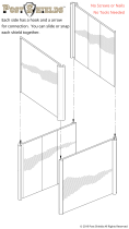
Standard System Layout Without Expansion
Standard System Layout With Multiple Expansions
Standard System Layout with Isolation Joints – End Power Interrupting Sections
Standard System Layout with Isolation Joints – Midpoint Power Interrupting Sections

Electrification FS Conductor Bar System Instruction Manual
October 2019
Page 14 of 34
Chapter 4.0: Modular Hangers
4.1: FS-H2, FS-H3, FS-H3L, FS-H4
4.1.(a): Remove nut(s), lock washer(s) and flat washer(s) from hanger base mounting bolt(s).
4.1.(b): Assemble hanger base to mounting bracket by inserting hanger bolt(s) through mounting
bracket hole(s).
4.1.(c): Assemble washer(s), lock washer(s) and bolt(s) to hanger bolt(s) and hand tighten.
4.1.(d): Assemble the snap-in hangers to the hanger base. Locate and follow the arrows on the
sides of the hangers to properly install to the base.
NOTE: Individual hangers are difficult to remove from the base; they are a one time assembly.
4.1.(e): Snap line elements into the snap-in-hangers.
4.1.(f): Verify the alignment of the system and tighten the nuts 15 ft-lb. (180 in-lb.)
NOTE: Tools Required: ½” Wrench or Socket

Electrification FS Conductor Bar System Instruction Manual
October 2019
Page 15 of 34
4.2: Mounting Centers
4.2.(a): Standard centers for hanger installation are 5’0” on horizontal and vertical systems.
4.3: Single Mounting Hanger (FS-SH)
4.3.(a): Remove nut, lock washer and flat washer from hanger base mounting bolt.
4.3.(b): Assemble hanger base to mounting bracket by inserting hanger bolt through mounting bracket hole
(NOTE: Minimum spacing of 1.75”).
4.3.(c): Assemble washer, lock washer and bolt to hanger base bolt and hand tighten.
4.3.(d): Snap line elements into the snap-in-hangers.
4.3.(e): Verify the alignment of the systems and tighten the nuts 15 ft-lb. (180 in-lb.).
NOTE: Tools Required: ½” Wrench or Socket
4.4: Single Mounting Hanger (FS-HST)
4.4.(a): Remove nut, lock washer, flat washer(s), and spacer from hanger base mounting bolt.
4.4.(b): Assemble hanger base to mounting bracket by inserting hanger bolt through mounting bracket hole
and spacer (NOTE: Minimum spacing of 1.75”).
4.4.(c): Assemble washers, lock washer and bolt to hanger base bolt and hand tighten.
4.4.(d): Snap line elements into the snap-in-hangers.
4.4.(e): Tighten the anchor hanger clamping nuts 8 ft-lb (48 in-lb.). Do not over-tighten.
4.4.(f): Verify the alignment of the systems and tighten the nuts 15 ft-lb. (180 in-lb.).
4.4.(g): Verify the line element is free to move along the length of the runway, and that the hanger is
secured to the insulation cover.
NOTE: Tools Required: ½” Wrench or Socket and 7/16” Wrench

Electrification FS Conductor Bar System Instruction Manual
October 2019
Page 16 of 34
4.5: Anchor Hanger (FS-AH)
4.5.(a): Slide anchor hanger assembly over the end of the line element near the mounting bracket.
NOTE: Slide the anchor hangers on the line element, with the clamping nut of the hanger facing the outside
of the system, for ease of installation.
4.5.(b): Remove nut, lock washer and flat washer from anchor hanger mounting bolt.
4.5.(c): Snap the line elements into the snap-in hangers located next to the anchor hanger location.
4.5.(d): Insert anchor hanger mounting bolt through the mounting bracket.
4.5.(e): Assemble washer, lock washer and bolt to hanger base bolt and hand tighten.
4.5.(f): Tighten anchor hanger clamping nuts 8 ft-lb. (48 in-lb.) Do not over-tighten.
4.5.(g): Verify alignment and tighten nut of mounting bolts 15 ft-lb. (180 in-lb.)
NOTE: Tools Required: ½” Wrench or Socket and 7/16” Wrench

Electrification FS Conductor Bar System Instruction Manual
October 2019
Page 17 of 34
Chapter 5.0: Joint Assembly
5.1: FS-JNTG, FS-JNTC
5.1.(a): Verify that the clamping plate is 1/8” below the underside of the joint assembly bracket.
If not, loosen or tighten the nuts to make the adjustment.
5.1.(b): Slide the joint assembly into upper slot of the end of the line element. Be sure the
clamping plate is properly located in the end of the line element.
5.1.(c): Slide the next line element into the open end of the joint assembly. Be sure the clamping
plate is properly located in the end of the line element.
5.1.(d): Center joint assembly over the adjoining line elements.
5.1.(e): Tighten one nut of the joint assembly 55 in-lb.
5.1.(f): Verify the end face of each line element is together.
5.1.(g): Tighten the other nut of the joint assembly 55 in-lb.
5.1.(h): Verify each nut on joint is tightened appropriately.
NOTE: Tools Required: 3/8” Wrench or Socket
NOTE: A liberal coating of joint compound FS-JNJC is recommended on all mating faces that conduct
current.
5.2: Joint Covers (FS-JNCV)
5.2.(a): Open joint end cover on each end of the joint (disengage lower locking tabs from each
side of cover).

Electrification FS Conductor Bar System Instruction Manual
October 2019
Page 18 of 34
5.2.(b): Remove packaging foam.
5.2.(c): Center joint cover over joint assembly.
5.2.(d): With light pressure, open the bottom of the joint cover sufficient to clear the sides of the
line element. Damage may occur to joint cover if it is spread beyond 1¼” wide.
5.2.(e): Push joint cover down until lower lips of cover clear the bottom of the line element. If
cover does not clear bottom of line element, verify the cover is centered between joint assembly
bolts.
5.2.(f): Push on sides of joint cover so lips are positioned under the line elements.
5.2.(g): Pull up on the joint cover so the lips are in contact with bottom of the line element cover
and insulate the vertical face of the exposed conductor bar.
5.2.(h): Fold down flaps at each end of the joint cover.
5.2.(i): Fold the locking tabs around the side of the joint cover and snap them into the slots along
the side of the joint cover.
5.3: End Cover (FS-END)
5.3.(a): Verify that the clamping plate is 1/8” below the underside of the end joint connector. If it
is not, loosen or tighten the nuts to make the adjustment.
5.3.(b): Slide end cap hardware into slot at end of the line element.

Electrification FS Conductor Bar System Instruction Manual
October 2019
Page 19 of 34
5.3.(c): Push end cap hardware until it comes in contact with the conductor bar cover, and
tighten the nut 55 in-lb. Trim the bolt to be flush with the nut.
5.3.(d): Push the end cover boot over the end of the bar and end cap hardware. Manipulate end
cover boot until the nut relief in the boot is directly over the end cap hardware.
The boot may become less pliable in low ambient temperature installation. Keeping the boot in a
warm location (+65°F) until needed is recommended.
NOTE: Tools Required: 3/8” Wrench or Socket
Ensure trimmed
fastener

Electrification FS Conductor Bar System Instruction Manual
October 2019
Page 20 of 34
Chapter 6.0: Isolation Joint Assembly
6.1: FS-JNIS
6.1.(a): Verify that the clamping plate is 1/8” below the underside of the isolation joint plastic. If
not, loosen or tighten the nuts to make the adjustment.
6.1.(b): Slide the joint assembly into upper slot of the end of the line element. Be sure the
clamping plate is properly located in the end of the line element.
6.1.(c): Slide the next line element into the open end of the joint assembly. Be sure the clamping
plate is properly located in the end of the line element.
6.1.(d): Ensure that the running surfaces are aligned.
6.1.(e): Ensure that the end of each bar is touching the isolation joint.
6.1.(f): Tighten the nuts of the isolation joint assembly to 55 in-lb.
6.1.(g): Verify each nut on joint is tightened appropriately.
NOTE: Tools Required: 3/8” Wrench or Socket
6.2: Joint Covers (FS-JNCV)
6.2.(a): Open joint end cover on each end of the joint (disengage lower locking tabs from each
side of cover).
6.2.(b): Remove packaging foam.
6.2.(c): Center joint cover over the isolation joint assembly.
6.2.(d): With light pressure, open the bottom of the joint cover sufficient to clear the sides of the
line element. Damage may occur to joint cover if it is spread beyond 1¼” wide.
/