Page is loading ...

FR33
MAINBOARD
MANUAL
DOC No.: M00301
Rev. : A0
Date : 12, 2000
Part No. : 25-11505-20

i
Table of Contents
Table of Contents
Chapter 1 Overview
Package Checklist ...................................................................... 1-1
The FR33 Mainboard ................................................................ 1-2
Main Features ................................................................................ 1-3
ACPI Ready ................................................................................... 1-4
Chapter 2 Installation Procedures
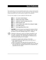
Quick Reference (from Page 2-2 to 2-4) .......................................... 2-2
Mainboard Layout .................................................................... 2-2
1). Clear CMOS Enable ...................................................... 2-3
2). Front Panel Block Cable Connection ............................ 2-3
3). CPU Fan Installation .................................................... 2-4
1). Set System Jumpers .................................................................. 2-5
Clear CMOS: CLR_CMOS ................................................. 2-6
2). Install Memory Modules .......................................................... 2-6
3). Install the CPU .......................................................................... 2-7
4). Install Expansion Cards ............................................................. 2-8
5). Connect Devices ....................................................................... 2-10
Floppy Diskette Drive Connector: FDD1 .......................... 2-10
IDE HDD Device Connectors: PRIMARY, ISECONDARY . 2-11
Infrared Connector: IR ....................................................... 2-11
ATX Power Connector: ATX ............................................ 2-12
CPU Fan Connector: JFAN1 .............................................. 2-12
System Case Fan Connector: JFAN2 ................................. 2-13
Wake-On-LAN Connector: WOL1 .................................... 2-13
Wake-On-Ring Connector: WOR1 .................................... 2-14
CD Audio-In Connector: CD_IN, CD_IN1 ........................ 2-14
Front Panel Block Connector: J3 ....................................... 2-15
PS/2 Keyboard and Mouse Connector: KB, MS ............... 2-16
Universal Serial Bus Connectors: Rear USBs
and Front USBs ................................................................. 2-16
Serial Port Connectors: COM1, COM2 .............................. 2-17
Video Graphics Accelerator Connectors: VGA .................. 2-17

ii
FR33 Mainboard Manual
Chapter 3 BIOS Setup
CMOS Setup Utility ....................................................................... 3-1
Standard CMOS Setup ................................................................... 3-2
Advanced BIOS Features .............................................................. 3-4
Advanced Chipset Features .......................................................... 3-8
Integrated Peripherals .................................................................... 3-12
Power Management Setup ............................................................. 3-17
PnP/PCI Configurations ................................................................. 3-21
PC Health Status ............................................................................ 3-23
Frequency/Voltage Control ............................................................ 3-24
Load Fail-Safe Defaults .................................................................. 3-25
Load Optimized Defaults ................................................................ 3-25
Supervisor/User Password ............................................................ 3-26
Save and Exit Setup ....................................................................... 3-27
Exit without Saving ........................................................................ 3-27
Quick Reference (German) G-1
Quick Reference (French) F-1
Quick Reference (Spanish) S-1
Quick Reference (Japanese) J-1
Quick Reference (Chinese) C-1
Quick Reference (Simplified Chinese) |||||||||||||SC-1
Printer Connector: LPT ...................................................... 2-18
Audio I/O Jacks: LINE_OUT, LINE_IN, MIC_IN,
FNT_AUDIO ..................................................................... 2-18
GAME/MIDI Connector: GAME ....................................... 2-19

1 - 1
Overview
Overview
Chapter 1
The Micro ATX, Socket 370 1stMainboard FR33 supports both the latest
generation Intel® and Cyrix processors. Intels new Celeron FC-PGA and
super fast Pentium FC-PGA Pentium®III processors are supported with Front
Side Bus speeds of 66 /100/133 MHz, while Cyrix III Processors are supported
at Front Side Bus speeds of 100/133 MHz.
The 1stMainboard FR33 is built around the new VIA Apollo PLE
(VT8601+686A) chipset supporting both DVD and AGP 1/2x, thus ensuring
photo-realistic 3D. Onboard AC97 sound ensures high quality audio, while
providing the option of being disabled through the BIOS. Support for the
Ultra DMA/66 protocol ensures for high data transfer speeds especially for
long sequential transfers required by audio/visual applications. With 2 DIMM
there is up to 1 GB available SDRAM.
Expansion is provided by 1 AMR, 1 ISA and 2 PCIs. I/O connections include
2 serial ports, 1 parallel port, 1 VGA port, 1 PS/2 mouse and keyboard connec-
tor, 4 USB connectors and 1 media connector (Line-In, Line-Out, Mic-In, Game/
Midi).
Package Checklist
If you discover any item below was damaged or lost, please contact your
vendor.
þ The mainboard þ This user manual
þ One FDD cable þ One HDD cable
þ One ATA/66 cable þ Two software CDs (CD Pro, CD Plus)
þ

1 - 2
FR33 Mainboard Manual
The FR33 Mainboard

1 - 3
Overview
Main Features
■ Easy Installation
||BIOS with support for Plug and Play, auto detection of IDE hard drives,
||LS-120|drives, IDE ZIP drives, Windows 95, Windows 98, Windows ME,
|Windows NT, Windows 2000, |and OS/2.
■ Leading Edge Chipset
VIA Apollo PLE133 (VT8601+686A) chipset provides integrated DRAM
controllers with new Dynamic Power Management Architecture (DPMA),
concurrent PCI (2.1), AGP 1.0 compliant and USB. It offers integrated
Trident graphics, DVD-capable multimedia (MPEG-2 & AC-3) accelerators
■ Advanced High Performance Memory Controller
Accepts up to 1GB DRAM using two DIMMs of 32, 64, 128, 256, 512MB
with support for lightenning-fast PC133 SDRAM. Supports FP, EDO,
SDRAM.
■ Enhanced IDE Controller with Ultra DMA/33 and Ultra DMA/66
Support
Enhanced IDE controller features two dual-channel connectors that up to
four enhanced IDE devices, including CD-ROM and Tape Backup Drives,
as well as Hard Disk Drives supporting the new Ultra DMA/66 protocol.
Standard PIO Mode 3, PIO Mode 4, DMA Mode 2, DMA Mode 4 devices
are also supported.
■ Flexible Processor Support
Onboard CPU socket supports:
Intel® Celeron FC-PGA 533/566/600/633/667/700/733/766 MHz at 66 MHz
FSB; Intel® Celeron FC-PGA 800 MHz at 100 MHz FSB
Intel® Pentium III FC-PGA 500/550/600/650/700/750/800/850 MHz at
100MHz FSB
Intel® Pentium III FC-PGA 533/600/667/733/800/866/933 MHz/1 GHz at
133MHz FSB
Cyrix® III 533-650 MHz and beyond* at 100/133 MHz FSB
(*: not yet test)

1 - 4
FR33 Mainboard Manual
■ AMR, ISA and PCI Expansion Slots
One AMR (Audio Modem Riser), one ISA Bus expansion slot and two
PCI Bus expansion slots provided the room to install a full range of add-
on cards.
■ Compact Onboard Audio Subsystem
Embeded in VIA 686A, the audio processor offers mainly in the aspects
of dual full-duplex Direct Sound channels, PCI master interface, stan-
dard AC97 (1.0/2.0) Codec interface, direct two game ports and one MIDI
port interface, and complete software driver support for Windows 95/98/
NT.
■■
■■
■ Super Multi Input/Output (I/O) Support
Embeded in 686A, the features that included are dual full-duplex Direct
Sound channels between system memory and AC97 link; PCI master in-
terface with bursting capability; standard AC97 Codec interface (1.0/2.0);
hardware SoundBlaster Pro for Windows DOS box and real-mode DOS
legacy compatibility; plug and play with 4 IRQ, 4 DMA, and 4 I/O space
options for SoundBlaster Pro and MIDI hardware.
■■
■■
■ Convenient Rear Panel USB Connection Support
Two USB ports integrated in the rear I/O panel and two USB ports for
front panel connection allow convenient and high-speed Plug and Play
connections to the growing number of USB compliant peripheral devices
on the market.
ACPI Ready
This mainboard fully implements the new ACPI (Advanced Configuration and
Power Interface) 1.0 Hardware and BIOS requirement. If you install ACPI aware
of operating system, such as Windows 98, you fully utilized the power saving
under ACPI. (Windows 2000/ME Professional supports ACPI functions.)

2 - 1
Installation Procedures
Chapter 2
Installation Procedures
The mainboard has several user-adjustable jumpers on the board that allow you to
configure your system to suit your requirements. This chapter contains information
on the various jumper settings on your mainboard.
To set up your computer, you must complete the following steps:
■ Step 1 - Set system jumpers/switches
■ Step 2 - Install memory modules
■ Step 3 - Install the Central Processing Unit (CPU)
■ Step 4 - Install expansion cards
■ Step 5 - Connect ribbon cables, cabinet wires, and power supply
■ Step 6 - Set up BIOS software
■ Step 7 - Install supporting software tools
WARNING: Excessive torque may damage the mainboard. When
using an electric screwdriver on the mainboard, make sure that
the torque is set to the allowable range of 5.0 ~ 8.0kg/cm.
Mainboard components contain very delicate Integrated Circuit
(IC) chips. To prevent static electricity from harming any of the
mainboard’s sensitive components, you should follow the
following precautions whenever working on the computer:
1. Unplug the computer when working on the inside.
2. Hold components by the edges and try not to touch the IC
||||chips, leads, or circuitry.
3. Wear an anti-static wrist strap which fits around the wrist.
4. Place components on a grounded anti-static pad or on the bag
that came with the component whenever the components are
separated from the system.

2 - 2
FR33 Mainboard Manual
Mainboard Layout
Quick Reference (from Page 2-2 to 2-4)

2 - 3
Installation Procedures
1). Clear CMOS Enable
2). Front Panel Block Cable Connection

2 - 4
FR33 Mainboard Manual
3). CPU Fan Installation
This connector is linked to the CPU fan. When the system is in power saving mode, the
CPU fan will turn off; when it reverts back to full on mode, the fan will turn back on.
Without sufficient air circulation, the CPU may overheat resulting in damage
to both the CPU and the mainboard.
Damage may occur to the mainboard and/or the CPU fan if these pins are
used incorrectly. These are not jumpers, do not place jumper caps over these
pins.

2 - 5
Installation Procedures
1). Set System Jumpers
Jumpers are used to select the operation modes for your system. Some jump-
ers on the board have three metal pins with each pin representing a different
function. A 1 is written besides pin 1 on jumpers with three pins. To set a
jumper, a black cap containing metal contacts is placed over the jumper pin/s
according to the required configuration. A jumper is said to be shorted when
the black cap has been placed on one or two of its pins. The types of jumpers
used in this manual are shown below:
NOTE: Users are not encouraged to change the jumper settings
not listed in this manual. Changing the jumper settings improperly
may adversely affect system performance.

2 - 6
FR33 Mainboard Manual
2). Install Memory Modules
1. Locate the DIMM slots on the mainboard.
2. Install the DIMM straight down into the DIMM slot using both hands.
3. The clip on both ends of the DIMM slot will close up to hold the DIMM
in place when the DIMM reaches the slots bottom.
Clear CMOS: CLR_CMOS
The CMOS RAM is powered by the onboard button cell battery. To clear the
RTC data: (1). Turn off your computer, (2). Move the jumper to CLEAR, (3).
Move the jumper back to NORMAL, (4). Turn on your computer, (5). Hold
down the <Delete> key during bootup and enter BIOS Setup to re-enter user
preferences. However, if the pin cap keeps staying at pin pair 2-3, the system
can not boot up.

2 - 7
Installation Procedures
Press the clips with both hands to remove the DIMM.
3). Install the CPU
The mainboard has built-in Switching Voltage Regulator to support CPU Vcore
autodetection. That is, It has the ability to detect and recognize the CPU
voltage, clock, ratio and enables users to set up the CPU frequency from the
BIOS Setup Screen. Users can adjust the frequency through Frequency /
Voltage Control of the BIOS Setup Screen.

2 - 8
FR33 Mainboard Manual
CAUTION:
1. The heatsink and fan you installed must be approved by CPU
|||||manufactories.
2. The mainboard must be placed on a solid place to avoid shaking
|||||while install the heatsink and fan on the board.
3. The heatsink must be contact with the CPU top tightly.
4. Never run the processor without the heatsink properly and firmly
attached. PERMANENT DAMAGE WILL RESULT!
To install the CPU, do the following:
1. Lift the lever on the side of the CPU socket.
2. Handle the chip by its edges and try not to touch any of the pins.
3. Place the CPU in the socket. The chip has two notches to correctly locate
the chip. Align two notches of the processor with the two triangular
marks on the socket. Do not force the chip. The CPU should slide easily
into the socket.
4. Swing the lever to the down position to lock the CPU in place.
5. Install the cooling fan with heatsink on top of the installed CPU.
6. Place the mainboard (with the CPU, its cooling fan, and heatsink) into the
system chassis and affix it with screws.
4). Install Expansion Cards
This section describes how to connect an expansion card to one of your
systems expansion slots. Expansion cards are printed circuit boards that,
when connected to the mainboard, increase the capabilities of your system.
For example, expansion cards can provide video and sound capabilities. The
mainboard features one AMR, one ISA, and two PCI bus expansion slots.

2 - 9
Installation Procedures
CAUTION: Make sure to unplug the power supply when adding or
removing expansion cards or other system components. Failure to
do so may cause severe damage to both the mainboard and
expansioncards.
Always observe static electricity precautions.
Please read “Handling Precautions” at the start of this manual.
To install an expansion card, follow the steps below:
1. Remove the computer chassis cover and select an empty expansion
slot.
2. Remove the corresponding slot cover from the computer chassis.
Unscrew the mounting screw that secures the slot cover and pull
the slot cover out from the computer chassis. Keep the slot cover
mounting screw nearby.
3. Holding the edge of the peripheral card, carefully align the edge
connector with the expansion slot.
4. Push the card firmly into the slot. Push down on one end of the
expansion card, then the other. Use this rocking motion until the
addon card is firmly seated inside the expansion slot.

2 - 10
FR33 Mainboard Manual
5). Connect Devices
Floppy Diskette Drive Connector: FDD1
This connector provides the connection with your floppy disk drive.
The red stripe of the ribbon cable must be the same side with the Pin 1.
5. Secure the board with the mounting screw removed in Step 2. Make
sure that the card has been placed evenly and completely into the
expansion slot.
6. Replace the computer systems cover.
7. Setup the BIOS if necessary.
8. Install the necessary software drivers for the expansion card.

2 - 11
Installation Procedures
IDE Device Connectors: PRIMARY, SECONDARY
These two connectors are used for your IDE hard disk drives, CD drives, LS-
120|drives, or IDE ZIP drives. The red stripe of the ribbon cable must be the
same side with the Pin 1.
Infrared Connector: IR
This 5-pin connector is used to link with your IR device to allow transmission
of data to another system that also supports the IR feature. This module
mounts to a small opening on system cases that support it.

2 - 12
FR33 Mainboard Manual
CPU Fan Connector: CPU_FAN
This connector is linked to the CPU fan. When the system is in suspend mode,
the CPU fan will turn off; when it reverts back to fullon mode, the fan will turn
back on. Please refer to the CPU fan installation manual for more information.
ATX Power Connector: ATX
This 20-pin male block connector is connected to the ATX power supply. The
plug from the power supply will only insert in one orientation because of the
different hole sizes. Find the proper orientation and push down firmly making
sure that the pins are aligned.

2 - 13
Installation Procedures
System Case Fan Connector: CHS_FAN
The 3-pin connector allows you to link with the cooling fan on the system case
to lower the system temperature.
Wake-On-Lan Connector: WOL1
This 3-pin connector allows the remote servers to manage the system that
installed this mainboard via your network adapter which also supports WOL.
When you install such a LAN card, please read its installation guide for more
information.
/