Page is loading ...

www.furuno.com
A
ll brand and product names are trademarks, registered trademarks or service marks of their respective holders.
Installation Manual
GPS/WAAS COLOR CHART PLOTTER with FISH FINDER
Model GP-3700F
(Product Name: GPS PLOTTER/SOUNDER)
SAFETY INSTRUCTIONS ................................................................................................ i
SYSTEM CONFIGURATION ........................................................................................... ii
EQUIPMENT LISTS........................................................................................................ iii
1. MOUNTING..............................................................................................................1-1
1.1 Display Unit........................................................................................................................1-1
1.2 Antenna Unit ......................................................................................................................1-5
1.3 Installation of Transducers (Option)...................................................................................1-6
1.4 Installation of Sensors (Option)........................................................................................1-16
1.5 Trackball Control Unit (Option) ........................................................................................1-17
1.6 External Monitor (Locally Supplied) .................................................................................1-19
2. WIRING....................................................................................................................2-1
2.1 How to Connect the Unit....................................................................................................2-1
2.2 DIP Switch Settings .........................................................................................................2-11
2.3 Input/Output Data.............................................................................................................2-11
3. SETTING UP THE EQUIPMENT .............................................................................3-1
3.1 Language Setting...............................................................................................................3-2
3.2 Echo Sounder Setting........................................................................................................3-3
3.3 Sensor and NMEA Equipment Setting...............................................................................3-4
3.4 Own Ship Information Setting ............................................................................................3-6
3.5 Event Switch Setting..........................................................................................................3-8
3.6 Input/Output Port Setting ...................................................................................................3-9
3.7 DGPS Setting...................................................................................................................3-14
3.8 How to Control Charts......................................................................................................3-16
APPENDIX 1 JIS CABLE GUIDE .............................................................................AP-1
APPENDIX 2 INSTALLATION FOR TRANSDUCER (THRU-HULL MOUNT).........AP-2
APPENDIX 3 INSTALLATION OF TEMPERATURE SENSORS .............................AP-6
PACKING LISTS ......................................................................................................... A-1
OUTLINE DRAWINGS ................................................................................................ D-1
INTERCONNECTION DIAGRAM ................................................................................ S-1

7KHSDSHUXVHGLQWKLVPDQXDO
LVHOHPHQWDOFKORULQHIUHH
࣭)85812$XWKRUL]HG'LVWULEXWRU'HDOHU
$VKLKDUDFKR
1LVKLQRPL\D-$3$1
$ $35
3ULQWHGLQ-DSDQ
$OOULJKWVUHVHUYHG
% 129
3XE1R ,0(%
<27$ *3)

i
SAFETY INSTRUCTIONS
The installer must read the appropriate safety instructions before attempting to install the equip-
ment.
Indicates a potentially hazardous situation which, if not
avoided, could result in death or serious injury.
Indicates a potentially hazardous situation which, if not
avoided, may result in minor or moderate injury.
WARNING
CAUTION
Warning, Caution Prohibitive Action Mandatory Action
(Examples of symbols)
WARNING
Turn off the power at the
switchboard before beginning the
installation.
Fire or electrical shock can result if the
power is left on.
Be sure no water leaks in at the
transducer mounting location.
Water leakage can sink the vessel.
Also, confirm that vibrations will not
lossen the transducer. The installer of
the equipment is solely responsible for
the proper installation of the equip-
ment. FURUNO will assume no
responsibility for any damage associ-
ated with improper installation.
CAUTION
Ground the equipment to prevent
electrical shock and mutual interfer-
ence.
Use the proper fuse.
Use of an incorrect fuse may damage the
equipment.
Use only the specified power and
signal cable.
Fire or damage to the equipment can
result if a different cable is used.
CAUTION
Observe the following compass
safe distances to prevent interfer-
ence to a magnetic compass:
Standard
compass
Steering
compass
1.05 m
0.70 m
Trackball Control Unit
RCU-030
0.50 m
0.30 m
Display Unit
GP-3700F
Do not open the equipment unless
totally familiar with electrical
circuits and service manual.
Only qualified personnel can work
inside the equipment.
ELECTRICAL
SHOCK
HAZARD
The transducer cable must handled
carefully, following the guidelines
below.
- Keep fuels and oils away from the
cable.
- Locate the cable where it will not be
damaged.
- Do not paint the cable.
The cable sheath is made of chloro-
phrane or polychloride vinyl, which are
easily damaged by plastic solvents such
as toluene. Locate the cables away from
plastic solvents.
Do not turn the equipment on with the
transducer out of water.
The transducer can be damaged.

ii
SYSTEM CONFIGURATION
Environmental category
Units Category
Antenna Unit Exposed to the weather
Transducer Submerged or in continuous
contact with sea water
: Standard supply
: Optional or local supply
*
1
: Use when the display unit has
no beacon receiver.
*
2
: Use when the internal beacon
receiver is installed in the
display unit.
Other Units Protected from the weather
Speed/Temperature Sensor
ST-02MSB, ST-02PSB
Temperature Sensor
T-04MSB
520-5PSD, 520-5MSD, 520-PLD,
525-5PWD, 525T-PWD, 50B-6,
50B-6B, 200B-5S, 50/200-1T,
525T-BSD, 525T-LTD/12,
525T-LTD/20, 525STID-MSD,
525STID-PWD, SS60-SLTD/12,
SS60-SLTD/20, 526TID-HDD
*
3
: Required for 1 kW transducer
(50B-6, 50B-6B, 200B-5S
and 50/200-1T).
Display Unit
GP-3700F
Antenna Unit
GPA-020S
*1
Antenna Unit
GPA-021S
*2
Event Switch 1
Event Switch 2
External Monitor
USB Flash
Memory
NMEA0183 Equipment
(Radar)
NMEA0183 Equipment
(Autopilot FAP-330)
Ethernet HUB
HUB-101
Radar
AIS Receiver
24 VDC
Trackball Control Unit RCU-030
Matching Box
MB-1100
*3
Transducer
*4
NMEA2000 (CAN bus) Backbone
*6
NMEA2000 Equipment
(Autopilot
NAVpilot-700 series
*5
)
NMEA2000 Equipment
(Satellite Compass
TM
SC-30)
Rectifier
RU-3423
12-24 VDC
100/110/220/230 VAC
1
ø
, 50/60Hz
*4
: Optional transducer
*
5
: When connected to a NAVpilot-700 series which is
set to NAV mode, only one of either GP-3700 or
GP-3700F can be connected.
*
6
: Turn the GP-3700F power off before connecting
to the NMEA2000 network.

iii
EQUIPMENT LISTS
Standard Supply
*: Not supplied depending on configuration purchased.
Optional Supply
Name Type Code No. Qty Remarks
Display Unit GP-3700F - 1 With hard cover
Antenna Unit
GPA-020S -
1*
For GPS. Use when the display unit
has no beacon receiver.
GPA-021S -
For DGPS. Use when the internal bea-
con receiver is installed to the display
unit.
Installation Materials
CP14-08200 000-029-328
1
With antenna cable assy and mast
mount kit
CP14-08210 000-029-329
With antenna cable assy
Without mast mount kit
CP14-08220 000-029-330
Without antenna cable assy and mast
mount kit
Accessories FP14-03400 000-029-327 1
Spare Parts SP14-03601 001-246-900 1
Name Type Code No. Remarks
Trackball Control Unit RCU-030 -
Beacon Receiver Set OP14-80 000-029-392
Monitor Option OP14-82 000-029-467
Flush Mount OP14-83 000-029-394 For display unit
FM Fixture Assembly OP24-38 001-263-190 For trackball control unit
Antenna Unit
GPA-020S - For GPS
GPA-021S - For DGPS
Antenna Cable
Assembly
CP20-01700 004-372-110
30 m antenna extension cable,
w/CP20-01701
CP20-01720 001-207-980
40 m antenna extension cable,
w/CP20-01701
CP20-01710 004-372-120
50 m antenna extension cable,
w/CP20-01701
CP20-02700 004-381-160
30 m antenna extension cable,
w/CP20-02701
CP20-02720 001-207-990
40 m antenna extension cable,
w/CP20-02701
CP20-02710 004-381-170
50 m antenna extension cable,
w/CP20-02701
Joint Box TL-CAT-012 000-167-140-10 For LAN cable extension
Transducer
520-5PSD
*
-
Thru-hull mount,
plastic
600 W
520-PLD
*
-
Thru-hull mount,
plastic
520-5MSD
*
-
Thru-hull mount,
metal

EQUIPMENT LISTS
iv
Transducer
525-5PWD
*
-
Transom mount,
plastic
600 W
50/200-1T
*
-10 m
1 kW
50B-6 - 10 m
50B-6B - 15 m
200B-5S - 10 m
Triducer
525T-PWD
*
-
Transom mount,
plastic
600 W
525T-BSD
*
-
Thru-hull mount,
metal
525STID-MSD
*
-
Thru-hull mount,
metal
525STID-PWD
*
-
Transom mount,
plastic
525T-LTD/12
*
-
12° tilt, thru-hull
mount, metal
525T-LTD/20
*
-
20° tilt, thru-hull
mount, metal
SS60-SLTD/12
*
-
12° tilt, thru-hull
mount, stainless
steel
SS60-SLTD/20
*
-
20° tilt, thru-hull
mount, stainless
steel
526TID-HDD
*
-
Thru-hull mount,
metal, not required
MB-1100
1 kW
Matching Box MB-1100 - For 1 kW transducer
Rectifier RU-3423 -
Temperature Sensor T-04MSB - Thru-hull mount
Speed/Temperature
Sensor
ST-02MSB - Thru-hull mount, metal
ST-02PSB - Thru-hull mount, plastic
Inner Hull Mounting Kit 22S0191 -
Not compatible with bottom
discrimination display
Right Angle Mounting
Base
NO.13-QA330 001-111-910-10
For antenna unit
L-Angle Mounting
Base
NO.13-QA310 001-111-900-10
Handrail Mounting
Base
NO.13-RC5160 001-111-920-10
Mast Mounting Kit CP20-01111 004-365-780
Installation Materials
CP03-28920 000-082-660 30 m LAN cable, w/armor
CP03-28930 000-084-368 50 m LAN cable, w/armor
LAN Cable Assembly
MOD-WPAS0001-030+ 000-164-609-10
LAN cable with waterproofing
modular plug, 3 m
MOD-Z072-020+ 001-167-880-10 2 m
MOD-Z072-050+ 001-167-890-10 5 m
MOD-Z072-100+ 001-167-900-10 10 m
Cable Assembly
02S4147-2 001-258-330
For temperature and speed/tem-
perature sensor
TNC-PS/PS-3D-L15M-R 001-173-110-10 15 m antenna cable
Name Type Code No. Remarks

EQUIPMENT LISTS
v
Cable Assembly
M12-05BM+05BF-010 001-105-750-10
w/micro type con-
nectors, 1 m
For
NMEA
2000
connec-
tion
M12-05BM+05BF-020 001-105-760-10
w/micro type con-
nectors, 2 m
M12-05BM+05BF-060 001-105-770-10
w/micro type con-
nectors, 6 m
M12-05BFFM-010 001-105-780-10
w/micro type con-
nector, 1 m
M12-05BFFM-020 001-105-790-10
w/micro type con-
nector, 2 m
M12-05BFFM-060 001-105-800-10
w/micro type con-
nector, 6 m
CB-05PM+05BF-010 000-167-968-11
w/mini type connec-
tors, 1 m
CB-05PM+05BF-020 000-167-969-11
w/mini type connec-
tors, 2 m
CB-05PM+05BF-060 000-167-970-11
w/mini type connec-
tors, 6 m
CB-05BFFM-010 000-167-971-11
w/mini type connec-
tor, 1 m
CB-05BFFM-020 000-167-972-11
w/mini type connec-
tor, 2 m
CB-05BFFM-060 000-167-973-11
w/mini type connec-
tor, 6 m
3COX-2P-6C 5M 001-077-230-10 For external monitor, 5 m
3COX-2P-6C 10M 001-077-220-10 For external monitor, 10 m
MJ-A6SPF0012-050C 000-154-053-10
w/MJ connectors,
5 m
For
NMEA
0183
connec-
tion
MJ-A6SPF0012-100C 000-154-037-10
w/MJ connectors,
10 m
MJ-A6SPF0012-150C 000-161-513-10
w/MJ connectors,
15 m
MJ-A6SPF0003-020C 000-154-029-10
w/MJ connector,
2 m
MJ-A6SPF0003-050C 000-154-054-10
w/MJ connector,
5 m
MJ-A6SPF0003-100C 000-168-924-10
w/MJ connector,
10 m
MJ-A6SPF0003-150C 000-159-643-10
w/MJ connector,
15 m
Extension Cable
**
C332 10M 001-464-120 10 m transducer extension cable
*:
Compatible with ACCU-FISH
™
and bottom discrimination display
**: Use of the extension cable may cause the following problems:
• Reduced detection ability
• Wrong ACCU-FISH
™
information (fish length smaller than actual length, fewer fish detections, er-
ror in individual fish detection)/
• Wrong speed data
• No TD-ID recognition
Name Type Code No. Remarks

EQUIPMENT LISTS
vi
This page is intentionally left blank.

1-1
1. MOUNTING
1.1 Display Unit
The display unit can be installed on a desktop, overhead or flush mounted in a console
(option kit is required).
Mounting consideration
Select a mounting location, keeping in mind the following points:
• Select a location where the unit can easily be operated.
• Keep the unit out of direct sunlight.
The LCD can blackout if the unit is exposed to direct sunlight for a long time.
• Locate the unit way from places subject to water splash and rain.
• The temperature at the mounting location shall be between -15°C and +55°C.
• Locate the unit away from exhaust pipes and vents.
• The mounting location should be well ventilated.
• Select a location where shock and vibration are minimal.
• Referring to the outline drawings at the back of this manual, allow sufficient space
for maintenance and service.
• Select a mounting location considering the length of the cables to be connected to
the unit.
• Do not place items which should not get wet near the display unit.
There is the drain hole on the bottom of this unit. If water enters the unit from the
clearance around the trackball, water is drained from the drain hole.
• A magnetic compass will be affected if the unit is placed too close to the magnetic
compass. Observe the compass safe distances at the front of this manual to prevent
interference to a magnetic compass.
NOTICE
Do not apply paint, anti-corrosive sealant or contact spray to
coating or plastic parts of the equipment.
Those items contain organic solvents that can damage coating and
plastic parts, especially plastic connectors.

1. MOUNTING
1-2
1.1.1 Desktop or overhead mounting
1. Unfasten the knob bolts and remove the display unit from the bracket.
2. Secure the bracket to the mounting location with four self-tapping screws (φ5×20,
supplied).
3. Connect all necessary cables, referring section 2.1.
Note: Place the display unit face-down on a soft, clean surface to prevent damage
to the LCD.
4. Set the display unit in the bracket, then fasten the knob bolts.
1.1.2 Flush mounting in a console (option)
Use the optional flush mount kit OP14-83, for flush mounting the display unit.
Type: OP14-83, Code No.: 000-029-394
Note: Ensure the mounting location is flat, with no indents or protrusions, to allow a
secure fit.
1. Prepare a mounting hole in the installation location, using the supplied mounting
template.
2. Unfasten the two knob bolts to remove the display unit from the bracket.
Name Type Code No. Qty
F Mount Sponge TOP 14-083-1091-0 100-401-120-10 1
F Mount Sponge SIDE 14-083-1092-0 100-401-130-10 2
F Mount Sponge BOT 14-083-1093-1 100-401-141-10 1
Flush Mount Fixture OP03-228-1 001-258-040 1
Hexagonal Head Slot Bolt M8×15 000-162-916-10 2
Flat Washer M8 000-167-464-10 2
Front Fixing Plate 14-083-1094-0 100-401-150-10 1
Knob bolt
Bracket
Self-tapping screw
(Ø5×20, 4 pcs)

1. MOUNTING
1-3
3. Attach the F mount sponge TOP, F mount sponge SIDE and F mount sponge
BOT, referring to the following figure.
Note 1: Place the display unit face-down on a soft, clean surface to prevent dam-
age to the LCD.
Note 2: Take care not to cover the screw holes with the F mount sponges.
Note 3: Ensure there are no gaps between the sponges at their joining points.
4. Set the front fixing plate to the display unit from the rear side.
5. Connect all necessary cables, referring section 2.1.
6. Loosen the wing nuts and wing bolts of the flush mount fixture to move the protec-
tor to the fixture.
1: F mount sponge TOP (thick)
2, 3: F mount sponge SIDE
4: F mount sponge BOT (thin)
1
2
3
4
Display unit
Front fixing plate
Flush mount fixture
Flush mount fixture
Wing bolt
Wing nut
Protector
Move to fixture

1. MOUNTING
1-4
7. Attach the two flush mount fixtures to the unit, using flat washers (M8) and hexag-
onal head slot bolts (M8×15).
Use the knob bolt holes to fasten hexagonal head slot bolts.
8. Tighten the four wing bolts on the flush mount fixture until the protector contacts
the front fixing plate and the flush mounting fixture is firmly secured.
9. Tighten four wing nuts on the flush mount fixture.
10. Set the display unit to the mounting hole.
Note: Take care that cables connected to the unit are not pinched between the
unit and console.
11. Fasten the display unit with six self-tapping screws (φ5×20, supplied).
Flat washer (M8)
Flush mount fixture
Knob bolt hole
Front fixing plate
Hexagonal head
slot bolt (M8×15)
Wing bolt
Wing nut
Protector
Self-tapping screw
(Ø5×20, 6 pcs)

1. MOUNTING
1-5
1.2 Antenna Unit
1.2.1 Mounting
Install the antenna unit referring to the "INSTALLATION PROCEDURE" at end of
manual.
Mounting considerations
Select a mounting location, keeping in mind the following points:
• Select a location out of the radar and inmarsat beams. Those beams will obstruct
or prevent reception of the GPS satellite signal.
• The location should be well away from a VHF/UHF antenna. Harmonic waves from
a VHF/UHF antenna interfere with the GPS receiver.
• There should be no interfering objects within the line-of-sight to the satellites. An ob-
ject within line-of-sight to satellites, for example, a mast, may block reception or pro-
long acquisition time.
• Mount the antenna unit as high as possible to keep it free from interfering objects
and water spray. Freezing water can interrupt reception of the GPS satellite signal.
• If the antenna cable is to be passed through a hole in a bulkhead which is too small
to pass the connector, disassemble the connector with radio pincers and a monkey
wrench. After passing the cable through the hole, assemble the connector as below.
Gasket
Washer
Clamping nut
Shield
Pin (Solder.)
Housing

1. MOUNTING
1-6
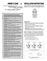
1.3 Installation of Transducers (Option)
This equipment can use thru-hull, transom or
inner hull mounted transducers. Select a
transducer mounting type according to the
ship’s type. The optional inner hull mounting
kit (type: 22S0191) is required for inner hull
mounting. For details about inner hull mount-
ing, see the installation instructions supplied
with the inner hull mounting kit.
Transducer mounting location
The performance of this fish finder is directly related to the mounting location of the
transducer. The installation should be planned in advance, keeping the length of the
transducer cable and the following factors in mind:
• Air bubbles and turbulence caused by movement of the boat seriously degrade the
sounding capability of the transducer. The transducer should, therefore, be located
in a position where water flow is the smoothest.
• Noise from the propellers adversely affects performance and the transducer should
not be mounted nearby. The lifting strakes are notorious for creating acoustic noise,
and these must be avoided by keeping the transducer inboard of them.
• The transducer must always remain submerged, even when the boat is rolling,
pitching or up on a plane at high speed.
• A practical choice would be somewhere between 1/3 and 1/2 of your boat's length
from the stern. For planing hulls, a practical location is generally rather far astern,
so that the transducer is always in water regardless of the planing attitude.
28
22
120
68
30
24
120
68
87
Unit: mm
520-5PSD
BOW
520-5MSD
●
Within the wetted bottom area
●
Deadrise angle within 15°
●
Position 1/2 to 1/3 of the hull from stern.
●
15 to 30 cm off center line (inside first lifting
strakes.)
DEEP V
HULL
HIGH SPEED
V HULL

1. MOUNTING
1-7
1.3.1 Thru-hull mount transducer
The thru-hull mount transducer provides the best performance of all, since the
transducer protrudes from the hull and the effect of air bubbles and turbulence near
the hull skin is reduced. If your boat has a keel, the transducer should be at least 30
cm away from it.
1. With the boat hauled out of the water, mark the location selected for mounting the
transducer on the bottom of the hull.
2. If the hull is not level within 15° in any direction, fairing blocks made out of teak
should be used between the transducer and hull, both inside and outside, to keep
the transducer face parallel with the water line. Fabricate the fairing block as
shown below and make the entire surface as smooth as possible to provide an
undisturbed flow of water around the transducer. The fairing block should be
smaller than the transducer itself to provide a channel to divert turbulent water
around the sides of the transducer rather than over its face.
3. Drill a hole just large enough to pass the threaded stuffing tube of the transducer
through the hull, making sure it is drilled vertically.
4. Apply a sufficient amount of high quality caulking compound to the top surface of
the transducer, around the threads of the stuffing tube and inside the mounting
hole (and fairing blocks if used) to ensure watertight mounting.
5. Mount the transducer and fairing blocks and tighten the locknut. Be sure that the
transducer is properly oriented and its working face is parallel to the waterline.
The wood block will swell when the boat is placed in the water. It is suggested that
the nut be tightened lightly at installation and re-tightened several days after the
boat has been launched.
Note: Do not over-stress the stuffing tube and locknut through excessive tightening
(maximum torque: 39 N•m), the plastic screw may damaged.
Transducer preparation
Before putting your boat in water, wipe the face of the transducer thoroughly with a
detergent liquid soap. This will lessen the time necessary for the transducer to have
Hole for
stuffing tube
Saw along
slope of hull.
Upper Half
Lower Half
BOW
Flat Hull
Deep-V Hull
Flat Washer
Rubber Washer
Fairing
Block
Hull
Hull
Flat Washer
Rubber
Washer
Cork
Washer

1. MOUNTING
1-8
good contact with the water. Otherwise the time required for complete "saturation" will
be lengthened and performance will be reduced.
Note: DO NOT paint the transducer. Performance will be affected.
1.3.2 Transom mount transducer
The transom mount transducer is very commonly employed, usually on relatively
small outboard boats. Do not use this method on an inboard motor boat because tur-
bulence is created by the propeller ahead of the transducer.
A suitable mounting location is at least 50 cm away from the engine and where the
water flow is smooth.
Installation for flat hulls
When the deadrise angle is less than 10°, install the transducer parallel with hull.
1. Drill four pilot holes for self-tapping screw (5×20) in the mounting location.
2. Coat the threads of the self-tapping screws (5x14) for the transducer with marine
sealant for waterproofing. Attach the transducer to the mounting location with the
self-tapping screws.
3. Adjust the transducer position so the transducer faces right to the bottom. If
necessary, to improve water flow and minimize air bubbles staying on the
transducer face, incline the transducer about 5° at the rear. This may require a
certain amount of experimentation for fine tuning at high cruising speeds.
Transom
Transom
Strake
Parallel with hull
Mount at the strake.
Less than 10°Less than 10°
Over 10°
Ø5×20
M5×14
5°
Taping

1. MOUNTING
1-9
4. Tape the location shown in the figure at step 3, then fill the gap between the
wedge front of the transducer and transom with epoxy material to eliminate any
air spaces.
5. After the epoxy hardens, remove the tape.
Installation for deep-V hulls
This method is employed on deep-V hulls and provides good performance because
the effects of air bubbles are minimal. Install the transducer parallel with water surface;
not flush with hull (Do not install the transducer parallel with hull). If the boat is placed
on a trailer care must be taken not to damage the transducer when the boat is hauled
out of the water and put on the trailer.
1.3.3 Inside hull mount
The transducer may also be installed inside the hull on FRP boats. However, this
installation method affects the ability to detect the bottom, fish and other objects
because the ultrasound pulse is weakened when it passes through the hull.
Necessary tools
The following tools are required:
• Sandpaper (#100)
• Marine sealant
• Water-filled plastic bag
Remarks on installation
• Do the installation with the ship moored at a dock, etc. The water depth should be
6.5 to 32 feet (2 to 10 meters).
• Install the transducer on the hull plate in the engine room.
• Turn off the engine while installing the equipment.
• Do not power the unit with the transducer in the air, to prevent damage to the
transducer.
• Do not use this method on a double layer hull.
Bracket
Transducer
2 to 5°
Epoxy material
Hull
NOTICE
This mounting method should not be used to mount the transducer
that supports the ACCU-FISH
TM
and bottom discrimination display,
since performance is greatly degraded.

1. MOUNTING
1-10
Mounting location
Select 2-3 locations considering the four points mentioned below.
• Mount the transducer at a location 1/2 to 1/3 of the length of your boat from the
stern.
• The mounting location is between 15 to 50 cm from the centerline of the hull.
• Do not place the transducer over hull struts or ribs which run under the hull.
• Avoid a location where the rising angle of the hull exceeds 15°, to minimize the ef-
fect of the boat's rolling.
Deciding the mounting location
The attenuation of the ultrasound pulse varies with the thickness of the hull. Select a
location where attenuation is the lowest. Decide the most suitable site from the loca-
tions selected.
1. Put the transducer into water-filled plastic bag.
Press the transducer against the chosen site.
2. Press /BRILL key to turn the power on.
3. Select the transducer on the menu, referring
section 3.2.1.
See page 3-1 for how to use the menu.
4. Press the MENU key to go back to the [ECHO
SOUNDER INITIAL SETTING] menu.
5. Select [1. ECHO SOUNDER SYSTEM SETTING] on the [ECHO SOUNDER INI-
TIAL SETTING] menu.
The [ECHO SOUNDER SYSTEM SETTING] menu has two pages. When the
page 2 is displayed, press the 1 key to open page 1.
1/3
1/2
Centerline
Transducer
mounting
location
50 cm
50 cm
15 cm
15 cm
Plastic bag
Water
Hull plate
ECHO SOUNDER SYSTEM SETTING SEL. PAGE ...
FISH ALARM LEVEL :
08
TRANSMISSION : TRANSMIT STOP
RANDOM KP : ON OFF
TRANSMISSION OUTPUT :
02
200kHZ TVG :
3
50kHz TVG :
3
ECHO OFFSET 200 kHZ :
+00%
ECHO OFFSET 50 kHZ :
+00%
BOTTOM LEVEL 200kHZ :
+000
BOTTOM LEVEL 50kHZ :
+000
ECHO SMOOTHING : SM1 SM2 SM3
SM4 OFF
DEPTH INFORMATION : LARGE SMALL OFF
TEMPERATURE GRAPH : SHOW HIDE
GRAPH COLORS :
ZOOM MARKER : SHOW HIDE
FISH ALARM LEVEL
[0]~[9] : NO. OF PAGE
[MENU] : BACK
TURN KNOB,
: SELECT PUSH KNOB : ENTER
: MOVE PAGE

1. MOUNTING
1-11
6. Select [TRANSMISSION OUTPUT].
7. Press the appropriate numeric key to set the transmission power to a level of “02”.
8. Press the MENU key several times or press the DISP key to close the menu.
9. Press the DISP key several times to show the echo sounder display.
Check if the bottom echo appears on the right side of the screen, in the display
area. If no bottom echo appears, repeat the procedure unit a suitable location is
found.
10. Turn the power off and remove the transducer from the plastic bag after deciding
the mounting location.
Attaching the transducer
1. Wipe the face of transducer with a cloth to remove water and any foreign material.
Lightly roughen the face with #100 sandpaper. Also, use the sandpaper to rough-
en the inside of the hull where the transducer is to be mounted.
2. Dry the face of the transducer and the hull,
then coat the transducer face and mount-
ing location with marine sealant. Harden-
ing begins in approx. 15 to 20 minutes so
do this step without delay.
3. Attach the transducer to the hull.
Press the transducer firmly down on the
hull and gently twist it back and forth to
remove any air which may be trapped in
the marine sealant.
4. Support the transducer with a piece of
wood to keep it in place while the sealant is
drying. It takes 24 to 72 hours to harden
completely.
5. Turn the power on and change the menu
setting as shown below.
1) Press the MENU key to open the main
menu.
2) Select [0. SYSTEM SETTING].
3) Select [8. ECHO SOUNDER INITIAL SETTING].
4) Select [1. ECHO SOUNDER SYSTEM SETTING], then press the 1 key to
open page 1.
5) Adjust the transmission output, echo offset and bottom level settings as
shown in the table below.
6. Press the DISP key to close the menu.
Menu Item Setting
TRANSMISSION OUTPUT 10
ECHO OFFSET 200 kHZ +20%
ECHO OFFSET 50 kHZ +20%
BOTTOM LEVEL 200 kHZ -40
BOTTOM LEVEL 50 kHZ -40
Transducer
Marine
sealant
Hull
Marine
sealant

1. MOUNTING
1-12
1.3.4 Triducer
Thru-hull mount triducer
The optional triducer 525STID-MSD is designed for thru-hull mounting. See
section 1.3.1 for how to install the 525STID-MSD.
Transom mount triducer
Mounting location
The optional transom mount triducer 525STID-PWD can be installed to the inboard or
outboard boats. To ensure the best performance, the sensor must be submerged in
aeration-free and turbulence-free water.
Mount the sensor close to the centerline of your boat. On slower heavier displacement
hulls, positioning it farther from the centerline is acceptable. Mount on the starboard
side at least 75 mm beyond the swing radius of the propeller, as shown in the following
figure.
ø
79
133
2.00"-12 UN
threads
ø
51
7
27
140
Unit: mm
BOW
Height without
speed sensor
191 mm (7-1/2")
Height with
speed sensor
213 mm (8-1/2")
Height
Height
75 mm minimum
beyond swing
radius
/