
1814E with FilterQuick
™
Electric Fryer
Service Manual
This manual is updated as new information and models are released. Visit our website for the latest manual.
Part Number: FRY_SM_8197318 11/2015
*8197318*
FOR YOUR SAFET
Y
Do Not Store or use gasoline or other
flammable vapors and liquids in the
vicinity of this or any other appliance.
Original Instructions

NOTICE
IF, DURING THE WARRANTY PERIOD, THE CUSTOMER USES A PART FOR THIS MANITOWOC FOOD
SERVICE EQUIPMENT OTHER THAN AN UNMODIFIED NEW OR RECYCLED PART PURCHASED
DIRECTLY FROM FRYMASTER, OR ANY OF ITS FACTORY AUTHORIZED SERVICERS, AND/OR THE
PART BEING USED IS MODIFIED FROM ITS ORIGINAL CONFIGURATION, THIS WARRANTY WILL BE
VOID. FURTHER, FRYMASTER DEAN AND ITS AFFILIATES WILL NOT BE LIABLE FOR ANY CLAIMS,
DAMAGES OR EXPENSES INCURRED BY THE CUSTOMER WHICH ARISE DIRECTLY OR INDIRECTLY,
IN WHOLE OR IN PART, DUE TO THE INSTALLATION OF ANY MODIFIED PART AND/OR PART
RECEIVED FROM AN UNAUTHORIZED SERVICER.
NOTICE
This appliance is intended for professional use only and is to be operated by qualified personnel
only. A Frymaster Authorized Servicer (FAS) or other qualified professional should perform
installation, maintenance, and repairs. Installation, maintenance, or repairs by unqualified
personnel may void the manufacturer’s warranty.
NOTICE
This equipment must be installed in accordance with the appropriate national and local codes
of the country and/or region in which the appliance is installed.
DANGER
All wiring connections for this appliance must be made in accordance with the wiring diagrams
furnished with the equipment. Wiring diagrams are located on the inside of the fryer door.
DANGER
Copper wire suitable for at least 167°F (75°C) must be used for power connections.
DANGER
The electrical power supply for this appliance must be the same as indicated on the rating and
serial number plate located on the inside of the fryer door.
DANGER
This appliance must be connected to the voltage and phase as specified on the rating and serial
number plate located on the inside of the fryer door.
NOTICE TO U.S. CUSTOMERS
This equipment is to be installed in compliance with the basic plumbing code of the Building
Officials and Code Administrators International, Inc. (BOCA) and the Food Service Sanitation
Manual of the U.S. Food and Drug Administration.
DANGER
Improper installation, adjustment, maintenance or service, and unauthorized alterations or
modifications can cause property damage, injury, or death. Read the installation, operating, and
service instructions thoroughly before installing or servicing this equipment.
DANGER
The front ledge of this appliance is not a step! Do not stand on the appliance. Serious injury can
result from slips or contact with the hot oil.
ii

NOTICE TO OWNERS OF UNITS EQUIPPED WITH CONTROLLERS
U.S.
This device complies with Part 15 of the FCC rules. Operation is subject to the following two
conditions: 1) This device may not cause harmful interference, and 2) This device must accept
any interference received, including interference that may cause undesired operation. While
this device is a verified Class A device, it has been shown to meet the Class B limits.
CANADA
This digital apparatus does not exceed the Class A or B limits for radio noise emissions as set
out by the ICES-003 standard of the Canadian Department of Communications.
Cet appareil numerique n’emet pas de bruits radioelectriques depassany les limites de classe A
et B prescrites dans la norme NMB-003 edictee par le Ministre des Communcations du Canada.
DANGER
Do not store or use gasoline or other flammable liquids or vapors in the vicinity of this or any
other appliance.
DANGER
The crumb tray in fryers equipped with a filter system must be emptied into a fireproof container
at the end of frying operations each day. Some food particles can spontaneously combust if left
soaking in certain shortening material.
WARNING
Do not bang fry baskets or other utensils on the fryer’s joiner strip. The strip is present to seal
the joint between the fry vessels. Banging fry baskets on the strip to dislodge shortening will
distort the strip, adversely affecting its fit. It is designed for a tight fit and should only be
removed for cleaning.
WARNING
Do not attach accessories to this fryer unless fryer is secured from tipping. Personal injury may
result.
WARNING
This equipment is intended for indoor use only. Do not install or operate this equipment in
outdoor areas.
DANGER
Adequate means must be provided to limit the movement of this appliance without depending
on or transmitting stress to the electrical conduit. A restraint kit is provided with the fryer. If the
restraint kit is missing contact your local KES.
DANGER
Prior to movement, testing, maintenance and any repair on your Frymaster fryer, disconnect all
electrical power from the fryer.
iii

Table of Contents
Section 1: Service Procedures
CAUTIONARY STATEMENTS .................................................................................................................................................................. i
ELECTRICAL POWER SPECIFICATIONS ............................................................................................................................................. v
1.1 General ................................................................................................................................................................................ 1-1
1.1.1 Reading Model Numbers ................................................................................................................................ 1-1
1.2 Replacing a Controller or Controller Wiring Harnesses ....................................................................................... 1-1
1.3 Replacing Component Box Components ................................................................................................................ 1-2
1.4 Replacing a High-Limit Thermostat ........................................................................................................................... 1-3
1.5 Replacing a Temperature Probe ................................................................................................................................. 1-3
1.6 Replacing a Heating Element ....................................................................................................................................... 1-4
1.7 Replacing Contactor Box Components .................................................................................................................... 1-7
1.8 Replacing a Frypot ........................................................................................................................................................... 1-8
1.9 Built-In Filtration System Service Procedures ......................................................................................................... 1-9
1.9.1 Filtration System Problem Resolution ................................................................................................. 1-9
1.9.2 Replacing the Filter Motor, Filter Pump and Related Components ........................................ 1-10
1.9.3 Replacing the Transformers, Relays, Interface Board or ATO Board ........................................ 1-11
1.10 Basket Lift Service Procedures ................................................................................................................................... 1-12
1.11 ATO (Automatic Top-Off) Service Procedures ...................................................................................................... 1-14
1.11.1 ATO (Automatic Top-Off) Troubleshooting) ........................................................................................ 1-14
1.11.2 ATO (Automatic Top-Off) Board Pin Positions and Harnesses ....................................................... 1-16
1.11.3 Replacing the ATO board, ATO Pump Relay or Transformer .......................................................... 1-17
1.11.4 Replacing the ATO Pump or Solenoid .................................................................................................... 1-17
1.12 MIB (Manual Interface Board) Service Procedures .............................................................................................. 1-17
1.12.1 Manually Draining, Refilling or Filtering using the MIB board ....................................................... 1-18
1.12.2 MIB (Manual Interface Board) Troubleshooting .................................................................................. 1-19
1.12.3 MIB (Manual Interface Board) Pin Positions and Harnesses ............................................................ 1-21
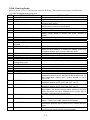
1.12.4 MIB (Manual Interface Board) Display Characters .............................................................................. 1-22
1.12.5 Replacing the MIB Board ............................................................................................................................ 1-22
1.12.6 Control Power Reset Switch ...................................................................................................................... 1-22
1.13 Bulk Service Issues ......................................................................................................................................................... 1-23
1.13.1 Bulk MIB Tests ................................................................................................................................................. 1-23
1.13.2 Bulk Wiring ...................................................................................................................................................... 1-24
1.13.3 Bulk Oil System Plumbing Schematic .................................................................................................... 1-25
1.13.4 Bulk Oil Test Quick Reference ................................................................................................................... 1-25
1.14 AIF (Automatic Intermittent Filtration) Service Procedures ............................................................................ 1-27
1.14.1 AIF (Automatic Intermittent Filtration) Troubleshooting................................................................ 1-28
1.14.2 AIF (Automatic Intermittent Filtration) Actuator Board Pin Positions ........................................ 1-29
1.14.3 Replacing an AIF (Automatic Intermittent Filtration) Board .......................................................... 1-30
1.14.4 Replacing a Rotary Actuator ...................................................................................................................... 1-30
1.15 FilterQuick
™
Controller Service Procedures ........................................................................................................... 1-31
1.15.1 FilterQuick
™
Controller Troubleshooting ............................................................................................... 1-31
1.15.2 FilterQuick
™
Controller Useful Codes ...................................................................................................... 1-33
1.15.3 Service Required Errors ............................................................................................................................... 1-34
1.15.4 Error Log Codes.............................................................................................................................................. 1-35
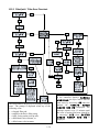
1.15.5 FilterQuick
™
Filter Error Flowchart ............................................................................................................ 1-36
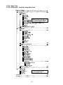
1.15.6 Menu Trees ...................................................................................................................................................... 1-37
1.15.6.1 FilterQuick
™
Controller Setup Menu Tree .......................................................................... 1-37
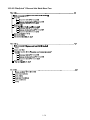
1.15.6.2 FilterQuick
™
Filter and Info Mode Menu Tree .................................................................. 1-38
1.15.7 FilterQuick
™
Controller Pin Positions and Harnesses ......................................................................... 1-39
1.15.8 OQS (Oil Quality Sensor) Troubleshooting ........................................................................................... 1-40
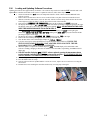
1.16 Loading and Updating Software .............................................................................................................................. 1-41
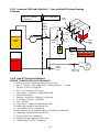
1.17 1814E with FilterQuick
™
Data Network Flowchart ............................................................................................... 1-42
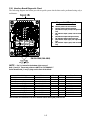
1.18 Interface Board Diagnostic Chart ............................................................................................................................. 1-43
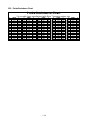
1.19 Probe Resistance Chart ................................................................................................................................................ 1-44
Wiring Diagrams
See 8197320 1814E with FilterQuick Elec Wiring Diagrams Manual
iv

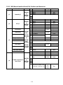
ELECTRICAL POWER SPECIFICATIONS
Three (3) Phase Requirements
MODEL VOLTAGE
WIRE
SERVICE
MINIMUM WIRE
SIZE
AWG (mm)
AMPS
(per leg)
1814E 14kW 208 3 6 (4.11) 39
1814E 14kW 240 3 6 (4.11) 34
1814E 14kW 480 3 8 (2.59) 17
1814E 14kW 220/380 4 6 (4.11) 21
1814E 14kW 240/415 4 6 (4.11) 20
1814E 14kW 230/400 4 6 (4.11) 21
1814E 17kW 208 3 6 (4.11) 48
1814E 17kW 240 3 6 (4.11) 41
1814E 17kW 480 3 6 (4.11) 21
1814E 17kW 220/380 4 6 (4.11) 26
1814E 17kW 240/415 4 6 (4.11) 24
1814E 17kW 230/400 4 6 (4.11) 25
1814E 22kW 208 3 4 (5.19) 61
1814E 22kW 240 3 4 (5.19) 53
1814E 22kW 480 3 6 (4.11) 27
1814E 22kW 220/380 4 6 (4.11) 34
1814E 22kW 240/415 4 6 (4.11) 31
1814E 22kW 230/400 4 6 (4.11) 32
Single Phase Requirements
MODEL VOLTAGE
WIRE
SERVICE
MINIMUM WIRE
SIZE
AWG (mm)
AMPS
(per leg)
1814E 14kW 208 2 3 (5.83) 68
1814E 14kW 240 2 4 (5.19) 59
1814E 14kW 480 2 8 (3.26) 30
v

1-1
1814E with FILTERQUICK
™
SERIES ELECTRIC FRYERS
CHAPTER 1: SERVICE PROCEDURES
1.1 General
Before performing any maintenance on your Frymaster fryer, disconnect the fryer from the electrical
power supply.
WARNING
To ensure the safe and efficient operation of the fryer, the electrical plug(s) must be
fully engaged and locked in their pin and sleeve socket.
When electrical wires are disconnected, it is recommended that they be marked in such a way as to
facilitate re-assembly.
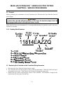
1.1.1 Reading Model Numbers
1.2 Replacing the Controller or the Controller Wiring Harnesses
1. Disconnect the fryer from the electrical power supply.
2. The controller bezel is held in place by tabs at the top and bottom. Slide the metal bezel up to
disengage the lower tabs. Then slide the bezel down to disengage the upper tabs.
3. Remove the two screws from the upper corners of the controller. The controller is hinged at the
bottom and will swing open from the top.

1-2
4. Unplug the wiring harnesses from the connectors on the back of the controller marking their
position for reassembly and disconnect the grounding wires from the terminals. Remove the
controller by lifting it from the hinged slots in the control panel frame.
5. Install the replacement controller. Reinstall the control panel assembly by reversing steps 1 thru 4.
6. Setup the controller following the instructions in section 1.4 in the FilterQuick
™
Controller
Operation manual. Setup MUST be performed prior to readdressing the system.
7. Once setup is complete on all replaced controllers, CYCLE POWER TO ENTIRE FRYER
SYSTEM. See section 1.12.6 to reset control power.
8. Check software version and if necessary update the software. If a software update was necessary,
follow the instructions to update the software in section 1.16.
1.3 Replacing Component Box Components
1. Disconnect the fryer from the electrical supply.
2. Drain cooking oil below the level of the probe or thermostat.
3. The controller bezel is held in place by tabs at the top and bottom. Slide the metal bezel up to
disengage the lower tabs. Then slide the bezel down to disengage the upper tabs.
4. Remove the top two screws in the upper corners of the controller.
5. Swing the controller out from the top and allow it to rest on its hinge tabs.
6. Disconnect the controller wiring harness and ground wire from the back of the controller and
remove the controller by lifting it from the hinge slots in the control panel frame.
7. Disconnect the wiring from the component to be replaced, being sure to make a note of where each
wire was connected.
8. Dismount the component to be replaced and install the new component, ensuring that any required
spacers, insulation, washers, etc. are in place.
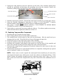
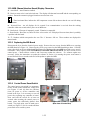
NOTE: If more room to work is required, the control panel frame assembly may be removed by
removing the hex-head screws which secure it to the fryer cabinet (see illustration below). If this
option is chosen, all controller assemblies must be removed per steps 1 thru 7 above. The cover
plate, on the lower front of the component box, may also be removed to allow additional access if
desired.
Ground Wire Terminal
20-Pin Connecto
r
Ground Wire Terminal
Communication Wires
Locator Wire
Drain Switch
and LED

1-3
9. Reconnect the wiring disconnected in step 7, referring to your notes and the wiring diagrams on
the fryer door to ensure that the connections are properly made. Also, verify that no other wiring
was disconnected accidentally during the replacement process.
10. Reverse steps 1 through 8 to complete the replacement and return the fryer to service.
1.4 Replacing a High-Limit Thermostat
1. Remove the filter pan and lid from the unit. Drain the frypots into a Shortening Disposal Unit
(SDU) or other appropriate METAL container using the controller “drain to pan option” or using
the MIB board in manual mode.
DANGER
DO NOT drain more than one full frypot into the SDU at one time.
2. Disconnect the fryer from the electrical power supply and reposition it to gain access to the rear of
the fryer.
3. Remove the four screws from both the left and right sides of the lower back panel.
4. Locate the high-limit that is being replaced and follow the two-black wires to the 12-pin connector
C-6. Note where the leads are connected prior to removing them from the connector. Unplug the
12-pin connector C-6 and using a pin-pusher push the pins of the high-limit out of the connector.
5. Carefully unscrew the high-limit thermostat to be replaced. Thoroughly clean threads to ensure
seal of replacement high limit.
6. Apply Loctite
™
PST 567 or equivalent sealant to the threads of the replacement and screw it
securely into the frypot.
7. Insert the leads into the 12-pin connector C-6 (see illustration below). For full-vat units (as viewed
from the rear of the fryer) the leads go into positions 1 and 2 of the connector. In either case,
polarity does not matter.
8. Reconnect the 12-pin connecting plug C-6. Use wire ties to secure any loose wires.
9. Reinstall the back panels, contactor plug guards, reposition the fryer under the exhaust hood, and
reconnect it to the electrical power supply to return the fryer to service.
1.5 Replacing a Temperature Probe
1. Lift the element out of the oil.
2. Disconnect the fryer from the electrical power supply and reposition it to gain access to the rear of
the fryer.
3. Remove the four screws from both sides of the lower back panel and upper back panel. Then
remove the two screws on both the left and right sides of the back of the tilt housing. Lift the tilt
housing straight up to remove from the fryer.

1-4
4. Locate the red (or yellow) and white wires of the temperature probe to be replaced. Note where
the leads are connected prior to removing them from the connector. Unplug the 12-pin connector
C-6 and using a pin-pusher push the pins of the temperature probe out of the connector.
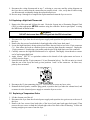
5. Remove the securing probe bracket and metal tie wraps that secure the probe to the element (see
illustration below). Remove the ground clip on the probe shield.
Probe
Bracket
Probe
Leads
Metal Wire Tie
6. Gently pull on the temperature probe and grommet, pulling the wires up the rear of the fryer and
through the element tube assembly.
7. Insert the replacement temperature probe (wires first) into the tube assembly ensuring that the
grommet is in place. Secure the probe to the elements using the bracket which was removed in
Step 5 and the metal tie wraps which were included in the replacement kit.
8. Route the probe wires out of the tube assembly following the element wires down the back of the
fryer through the Heyco bushings to the 12-pin connector C-6. Secure the wires to the sheathing
with wire ties. Attach the ground clip.
9. Insert the temperature probe leads into the 12-pin connector C-6 (see illustration below). For full-
vat units (as viewed from the rear of the fryer) the red (or yellow) lead goes into position 3 and the
white lead into position 4 of the connector. NOTE: Right and left refer to the fryer as viewed
from the rear.
10. Reinstall the ground clip on the probe shield.
11. Secure any loose wires with wire ties, making sure there is no interference with the movement of
the springs. Rotate the elements up and down, making sure that movement is not restricted and
that the wires are not pinched.
12. Reinstall the tilt housing, back panels and contactor plug guards. Reposition the fryer under the
exhaust hood and reconnect it to the electrical power supply to return the fryer to service.
1.6 Replacing a Heating Element
1. Perform steps 1-5 of section 1.5, Replacing a Temperature Probe.

1-5
2. Disconnect the wire harness containing the probe wiring, where the temperature probe is attached
to the element being replaced. Using a pin pusher, disconnect the probe wires from the 12-pin
connector.
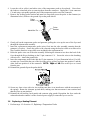
3. In the rear of the fryer disconnect the 6-pin connector for the left element (as viewed from the front
of the fryer) or the 9-pin connector for the right element from the contactor box. Press in on the
tabs on each side of the connector while pulling outward on the free end to extend the connector
and release the element leads (see photo below). Pull the leads out of the connector and out of the
wire sleeving.
4. Raise the element to the full up position and support the elements.
5. Remove the hex head screws and nuts that secure the element to the tube assembly and pull the
element out of the frypot. NOTE: The nuts inside the tube can be held and removed using the RE
element tube nut spanner, PN# 2304028. Full-vat elements consist of two dual-vat elements
clamped together. For full-vat units, remove the element clamps before removing the nuts and
screws that secure the element to the tube assembly.
6. If applicable, recover the probe bracket and probe from the element being replaced and install
them on the replacement element. Install the replacement element in the frypot, securing it with the
nuts and screws removed in Step 5 to the tube assembly. Ensure the gasket is between the tube and
element assembly.
7. Route the element leads through the element tube assembly and into the wire sleeving to prevent
chafing. Ensure that the wire sleeving is routed back through the Heyco bushing, keeping it clear
from the lift springs (see phots below and on the next page). Also ensure that the wire sleeving
extends into the tube assembly to protect the edge of the tube assembly from chafing the wires.
Press the pins into the connector in accordance with the diagram below, and then close the
connector to lock the leads in place. NOTE: It is critical that the wires be routed through the
sleeving to prevent chafing.
1
4
2
5
3
6
1
4
2
5
3
6
789
5
R
4R
6
R
1R
2
R
3R
Index Marker marks
Position 1
5L 4L6L 1L2L3L

1-6
Full vat element wire routing
Pull the element wires through the
bushings on either side of the frypot
and down the back. Element wires
should be routed to the right of the
ATO temperature probe on the back
wall of the frypot.
Element grounding and wire
routing
To ground the element wires, use the
hole in the frypot frame located under
the bushing that the element wires pass
through. Using a screw through the
ground wires ring terminal, connect it
to the frypot using the probe ground
clip. Use a tie wrap to tie up half of the
element wires after the wires are pulled
through the bushing. Do not pull tie
wrap tight, leave it slack at about one
inch
8. Reconnect the element connector ensuring that the latches lock.
9. Insert the temperature probe leads into the 12-pin wiring harness connector (see illustration
below). For full-vat units, the red lead goes into position 3 and the white into position 4. NOTE:
Right and left refer to the fryer as viewed from the rear.
10. Reconnect the 12-pin connector of the wiring harness disconnected in Step 2.
11. Lower the element to the full down position.
12. Reinstall the tilt housing, back panels and contactor plug guard. Reposition the fryer under the
exhaust hood, and reconnect it to the electrical power supply.

1-7
1.7 Replacing Contactor Box Components
1. If replacing a contactor box component in boxes above the filter pan, first remove the filter pan
and lid from the unit. If replacing components in fryers that have ATO boxes, the ATO box may
require removal.
2. Disconnect the fryer from the electrical power supply.
3. Remove the two screws securing the cover of the contactor box. The contactor boxes above the
filter pan are accessed by sliding under the fryer. They are located to the left and right above the
guide rails (see photo below). The contactor boxes for frypots not over the filter pan are accessed
by opening the fryer door directly under the affected frypot.
4. The contactors and relays are held on by threaded pin studs so that only removal of the nut is
required to replace the component.
5. After performing necessary service, reverse steps 1-4 to return the fryer to operation.
Left and right views of mechanical contactor box components.
Sometimes it is necessary to remove the entire contactor box to repair. Below are the instructions for
removing the far left contactor box.
1. Remove fryers from hood and remove all power to fryers.
2. Remove lower back panel.
3. Remove filter pan, lid and downspout splash shield.
4. Remove clevis clip from dispose handle at rear of fryer and let handle drop out of waste valve
bracket.
5. Remove two screws holding waste valve handle at front of fryer and remove bracket and handle
from fryer.
6. Remove AIF board and tuck wires out of the way of the contactor box for box removal.
7. Remove shipping brace that supports filter pump shelf brace to top of contactor box.
Remove two screws to
access contactor box
components above the
filter pan
.

1-8
8. Remove contactor box cover.
9. Unplug all wiring from front and rear of contactor box.
10. Remove two screws that hold element wire shield to rear of contactor box and remove wire shield.
11. Remove two screws that support contactor box at rear of box.
12. Remove two screws that support contactor box at front of box.
13. Lift contactor box up to clear left frame rail and slide to the right far enough that the left rear
corner of the pump and motor shelf protrude inside of the contactor box slightly.
14. Tip front of contactor box down and to the right slightly and then pull out from opening where
filter pan lid would rest.
15. Reverse above steps for reinstallation.
1.8 Replacing a Frypot
1. Drain the frypot into the filter pan or, if replacing a frypot over the filter system, into a Shortening
Disposal Unit (SDU) or other appropriate METAL container. If replacing a frypot over the filter
system, remove the filter pan and lid from the unit.
DANGER
DO NOT drain more than one full frypot into the SDU at one time.
2. Disconnect the fryer from the electrical power supply and reposition it to gain access to both the
front and rear.
3. Disconnect the fryer from the electrical supply.
4. Drain cooking oil.
5. The controller bezel is held in place by tabs at the top and bottom. Slide the metal bezel up to
disengage the lower tabs. Then slide the bezel down to disengage the upper tabs.
6. Remove the top two screws in the upper corners of the controller.
7. Swing the controller out from the top and allow it to rest on its hinge tabs.
8. Disconnect the controller wiring harness and ground wire from the back of the controller and
remove the controller by lifting it from the hinge slots in the control panel frame.
9. Remove the controllers by lifting them from the hinge slots in the control panel frame.
10. Remove the tilt housing and back panels from the fryer.
11. To remove the tilt housing, remove the hex-head screws from the rear edge of the housing. The
housing can be lifted straight up and off the fryer.
12. Remove the control panel by removing the screw in the center and the nuts on both sides.
13. Loosen the component boxes by removing the screws, which secure them in the cabinet.
14. Dismount the top cap by removing the nuts at each end that secure it to the cabinetry.
15. Remove the hex head screw that secures the front of the frypot to the cabinet cross brace.
16. Remove the top-connecting strip that covers the joint with the adjacent frypot.
17. Unscrew the nut located on the front of each section of drain tube, and remove the tube assembly
from the fryer.
18. Remove the actuators from the drain and return valves and disconnect the wiring.
19. Disconnect any auto filtration probes and auto top off sensors and wiring.
20. At the rear of the fryer, unplug the 12-pin connector C-6 and, using a pin pusher, disconnect the
high-limit thermostat leads. Disconnect any other probe wiring.
21. Disconnect the oil return flexline(s).
22. Raise the elements to the “up” position and disconnect the element springs.
23. Remove the machine screws and nuts that secure the element tube assembly to the frypot.
Carefully lift the element assembly from the frypot and secure it to the cross brace on the rear of
the fryer with wire ties or tape.

1-9
CAUTION
Ensure that filter screen is in place prior to
filter pad/paper placement and filter pump
operation. Improper screen placement is the
primary cause of filtration system
malfunction.
24. Carefully lift the frypot from the fryer and place it upside down on a stable work surface.
25. Recover the drain valve(s), oil return flexline connection fitting(s), actuators, AIF boards and high-
limit thermostat(s) from the frypot. Clean the threads and apply Loctite
™
PST 567 or equivalent
sealant to the threads of the recovered parts and install them in the replacement frypot.
26. Carefully lower the replacement frypot into the fryer. Reinstall the hex head screw removed in
step 11 to attach the frypot to the fryer.
27. Position the element tube assembly in the frypot and reinstall the machine screws and nuts
removed in step 24.
28. Reconnect the oil return flexlines to the frypot, and replace aluminum tape, if necessary, to secure
heater strips to the flexlines.
29. Insert the high-limit thermostat leads disconnected in step 20 (see illustration on page 1-3 for pin
positions).
30. Reconnect the actuators, ensuring the correct position of the drain and return valves.
31. Reconnect the auto filtration and auto top off probes.
32. Reinstall the drain tube assembly.
33. Reinstall the top connecting strips, top cap, tilt housing and back panels.
34. Reinstall controllers in the control panel frame and reconnect the wiring harnesses and ground
wires.
35. Reposition the fryer under the exhaust hood and reconnect it to the electrical power supply.
1.9 Built-in Filtration System Service Procedures
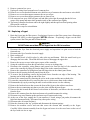
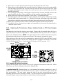
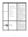
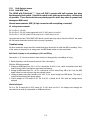
1.9.1 Filtration System Problem Resolution
One of the most common causes of filtration problems is placing the filter pad/paper on the bottom of
the filter pan rather than over the filter screen.
Whenever the complaint is “the pump is running, but
no oil is being filtered,” check the pre-filter and
ensure it is not clogged up. If so clean, dry and
replace it. If the pre-filter was clogged, check the
installation of the filter pad/paper, and ensure that the
correct size is being used and it was correctly
prepared in the filter pan. While you are checking the
filter pad/paper, verify that the O-rings on the pick-up
tube of the filter pan are in good condition. A missing
or worn O-ring allows the pump to take in air and
decrease its efficiency.
If the pump motor overheats, the thermal overload
will trip and the motor will not start until it is reset. If the pump motor does not start, press the red
reset switch (button) located on the rear of the motor.
Sediment Particle
Oil Flow
Up for reverse
Down for forward
Sediment Particle
Gear Rotation

1-10
If the pump starts after resetting the thermal overload switch, then something is causing the motor to
overheat. A major cause of overheating is when several frypots are filtered sequentially, overheating
the pump and motor. Allow the pump motor to cool at least 30 minutes before resuming operation.
Pump overheating can be caused by:
Solidified shortening in the pan or filter lines, or
Attempting to filter unheated oil or shortening (cold oil is more viscous, overloading the pump
motor and causing it to overheat).
If the motor runs but the pump does not return oil, there is a blockage in the pump or the pre-filter.
Incorrectly sized or installed paper/pads will allow food particles and sediment to pass through the
filter pan, into the pre filter and possibly into the pump. Remove the pre-filter and ensure it is clean.
When sediment enters the pump, the gears bind, causing the motor to overload, again tripping the
thermal overload. Shortening that has solidified in the pump will also cause it to seize, with the same
result.
A pump seized by debris or hard shortening can usually be freed by manually moving the gears with a
screwdriver or other instrument.
Disconnect power to the filter system, remove the input plumbing from the pump, and use a
screwdriver to manually turn the gears.
● Turning the pump gears in reverse will release a hard particle.
● Turning the pump gears forward will push softer objects and solid shortening through the pump
and allow free movement of the gears.
Incorrectly sized or installed paper/pads will also allow food particles and sediment to pass through
and clog the suction tube on the bottom of the filter pan or the pre-filter. Particles large enough to
block the suction tube may indicate that the crumb tray is not being used. Pan blockage can also occur
if shortening is left in the pan and allowed to solidify. Blockage removal can be accomplished by
forcing the item out with an auger or drain snake. Compressed air or other pressurized gases should
NEVER be used to force out the blockage.
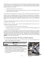
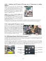
1.9.2 Replacing the Filter Motor, Filter Pump, and Related Components
1. Remove the filter pan and lid from the unit. Drain the frypot into a Shortening Disposal Unit
(SDU) or other appropriate metal container.
DANGER
DO NOT drain more than one full frypot into the SDU at
one time.
2. Disconnect the fryer from the electrical power supply and
reposition it to gain access to both the front and rear.
3. Disconnect the flexline running to the oil-return manifold at
the rear of the fryer as well as the pump suction flexline at the
end of the filter pan connection (see photo to the right).
4. Loosen the nut and bolt which secure the bridge to the oil-
return manifold.
Disconnect flexlines indicated by
the arrows.

1-11
5. Remove the cover plate from the front of the motor and disconnect the motor wires.
6. Remove the two nuts and bolts which secure the front of the bridge to the cross brace and carefully
slide the bridge rearward off the cross brace until its front end can be lowered to the floor. Undo
the single nut holding it in place in back. Be careful not to let the rear of the bridge slip off the
manifold at this point.
7. Get a good grip on the bridge, carefully pull it forward off the oil-return manifold, and lower the
entire assembly to the floor. Once on the floor, pull the assembly out the front of the fryer.
8. When required service has been completed, reverse steps 4-7 to reinstall the bridge.
9. Reconnect the unit to the electrical power supply, and verify that the pump is functioning correctly
using the MIB board in manual mode (i.e., using the fill function when engaged, the motor should
start and there should be strong suction at the intake fitting and outflow at the rear flush port.)
10. When proper operation has been verified, reinstall the back panels and the filter pan and lid.
11. Reconnect it to the electrical power supply and reposition the fryer under the exhaust hood to
return the fryer to service.
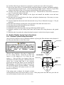
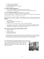
1.9.3 Replacing the Transformers, Relays, Interface Board, or ATO Board (singles
only)
Disconnect the fryer from the electrical power supply. Remove the left controller from the fryer to
expose the interior of the left component box. The transformer and relay on the left are located as
shown in the illustration below. NOTE: The right component box is identical to the left except that
the transformer and relay on the left side are not present. Once replaced, reconnect the power.
When replacing a filter relay in the left component box, ensure the 24VDC relay (8074482) is used.
Similar Frymaster fryers use a 24VAC relay, which can lead to confusion. The 24VDC is used in the
1814E with FilterQuick™ fryer. If replacing the ATO board see NOTE in section 1.11.3.
1-1814E Single Control Box Multiple Batteries
1.10 Basket Lift Service Procedures
1814E with FilterQuick
™
Series electric fryers may be equipped with automatic basket lifts. Basket
lifts always come in pairs, although each operates independently.
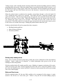
A modular basket lift (illustrated below) is a self-contained sub-assembly consisting of a pair of
toothed rods, which support removable basket lift arms, a pair of reversible-drive gear motors, and
four microswitches. The gear motors engage the teeth of the rods, moving them up or down
depending upon the motors’ direction of rotation. The microswitches at the upper and lower limits of
movement stop the motors when the basket is in the full up or full down position.

1-12
100-120V Configuration
208-250V Configuration
Timing circuitry in the controller initiates and stops basket lift operation depending upon the variables
programmed by the operator. When the product button is pressed, the timing circuitry activates a coil
in the basket lift relay to supply power to the lower microswitch. The microswitches stop the motor at
the lift’s upper and lower travel limits and reverse the direction of current flow thus reversing the
motor direction.
When the product button is pushed on the controller, current flows through a coil in the basket lift
relay, causing the lower circuit to be activated. The basket lift lowers, closing the normally open
upper-micro-switch. When the downward-moving rod opens the lower normally closed microswitch,
the power to the motor ceases to flow. When the controller times out, the current to the relay coil is
cut, allowing the upper circuit to be activated. The basket lift rises and re-closes the lower
microswitch. When the basket lift rod clears the upper microswitch, the microswitch reopens, power
to the circuit is cut, and the motor stops. Pushing the product button restarts the cycle.
Problems with the basket lift can be grouped into three categories:
● Binding/jamming problems
● Motor and gear problems
● Electronic problems
Binding and Jamming Issues
Noisy, jerky or erratic movement of the lifts is usually due to lack of lubrication of the rods and their
bushings. Apply a light coat of Lubriplate
®
or similar lightweight white grease to the rod and
bushings to correct the problem.
With the modular basket lift, another possible cause of binding is improper positioning of the motor,
which prevents the gear from correctly engaging the teeth in the rod. To correct the problem, loosen
the screws that hold the motor in place and move it forward or backward until the rod has just enough
slack to be rotated slightly.
Motor and Gear Issues
With the modular basket lift, the most likely problem to be encountered in this category is erratic
motion of the lift due to a worn drive gear. Failure to keep the lift rod and bushings properly

1-13
lubricated will cause unnecessary wear of the gear. The problem is corrected by replacing the worn
gear.
If the lift cycles correctly but fails to remain in the up position (i.e., goes up, but then slowly settles
back down into the frypot), the problem is a failed motor brake. A failed motor brake cannot be
repaired and requires replacement of the motor itself.
If power is reaching the motor but the motor fails to run, the motor is burned out and must be replaced.
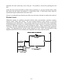
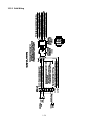
Electronic Issues
Within this category are problems associated with the relays, microswitches, capacitors, resistors,
interface board, wiring, and controls. The most common problem in this category is a lift that
continuously travels up and down. This is usually caused by a microswitch that is out of adjustment.
Troubleshooting the electronics of a modular basket lift is simply a process of verifying current flow
through the individual components up to and including the motor. Using a multimeter set to the 250
VAC range, check the connections on both sides of the component for the presence of the applied line
voltage. The schematic below and the wiring diagrams in in the 1814E with FilterQuick wiring
diagram manual PN 8197320 can identify the components and wiring connection points.

1-14
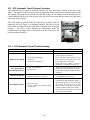
1.11 ATO (Automatic Top-off) Service Procedures
The automatic top-off system is activated when the oil level falls below a sensor in the rear of the
frypot. The signal is sent to the ATO board to engage the return actuator to the frypot and turn on the
ATO pump. The pump draws oil from the JIB (Jug In Box) or Oil Saddle reservoir through the rear
return manifold into the rear of the frypot. Once the oil level has satisfied the sensor, the pump turns
off and the actuator closes.
The ATO board is located inside the control box in single units, or
behind the JIB (see Figure 1) in multiple batteries. The power for the
ATO board is supplied from the right hand component box in multiple
batteries. The power passes through the transformer inside the
component box on single units to the board or to the ATO box to the
board in multiple batteries.
Figure 1
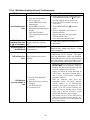
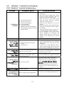
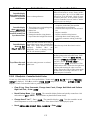
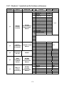
1.11.1 ATO (Automatic Top-off) Troubleshooting
Problem Probable Causes Corrective Action
Frypot tops off cold.
Incorrect setpoint
Ensure setpoint is correct.
No power to ATO board
A. J5 connection unplugged
B. Fuse blown
C. Transformer malfunction
A. Check to ensure J5 on front of ATO board
is fully locked into connector.
B. Ensure fuse below right control box is not
blown and fuse on the right side of ATO
box, if applicable, is not blown.
C. Check that proper voltage is present at
transformer. See table in section 1.11.2.
One vat tops off but
other vats fail to top off.
A. Loose wire connection.
B. Actuator issue
A. Ensure all wiring harnesses are securely
connected to ATO board and solenoids.
B. Check return actuator to ensure actuator is
functional.
Incorrect vat tops off.
A. Wired incorrectly.
B. Flexlines connected to wrong vat.
A. Check wiring.
B. Switch flexlines to correct vat.
One vat doesn’t top off.
A. Filter error exists.
B. Actuator, pump, loose connection, RTD
or ATO issue.
A. Clear filter error properly. When
CHANGE FILTER PAPER YES/NO is
displayed, do NOT press any button until
the pan has been removed for at least
thirty seconds. After thirty seconds the
controller returns to OFF or last display.
B. Check actuator, ATO pump, ATO board,
wire connections and RTD.

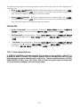
1-15
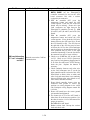
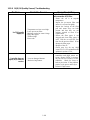
Problem Probable Causes Corrective Action
Frypots won’t top off.
A. Empty JIB or oil saddle.
B. Crumb build up around sensor.
C. Probe temperature lower than setpoint.
D. Oil is too cold.
E. Bad Connection
F. ATO board power loss
G. Failed transformer/harness
H. ATO pump failed
I. Failed ATO board.
J. ATO lines/pump plugged
A. Ensure JIB or oil saddle has oil.
B. Clean crumbs from opening surrounding
sensor.
C. Check to see that fryer is heating. Fryer
temperature must be at setpoint. Check
probe resistance. If probe is bad, replace
the probe.
D. Ensure that the oil in the JIB or oil saddle
is above 70°F (21°C).
E. With the controller OFF, press the
temperature button and ensure the ATO
software version appears. If not, the
connection between the AIF and the ATO
board may be bad. Ensure the 6-pin CAN
connectors are tight between AIF (J4 and
J5) and ATO (J10) boards.
F. Power to the ATO board has been cut off.
Restore power to the board and clear any
service required errors.
G. Ensure transformer in ATO box is
functioning properly. Check power from
transformer to ATO board. Ensure all
harnesses are plugged securely into place.
H. Ensure pump is operational. Check
voltage to pump. Replace the pump if
defective.
I. Check for proper voltages using the pin
position chart found in section 1.11.2. If
the ATO is found defective, replace ATO
board and clear any errors.
J. Clear the lines/pump.
Controller displays
SERVICE
REQUIRED – ATO
BOARD
A. Loose or bad fuse
B. Bad Connection
C. ATO Board power loss
A. Ensure fuse if applicable on right side of
ATO box is secure and good. If the
controller above the ATO box is missing
power check the fuse below the
component box.
B. With the controller OFF, press the
temperature button and ensure the ATO
software version appears. If not, the
connection between the AIF and the ATO
board may be bad. Ensure the 6-pin CAN
connectors are tight between AIF (J4 and
J5) and ATO (J9 or J10) boards.
C. Power to the ATO board has been cut off.
Ensure there is correct voltage to the
ATO transformer. Restore power to the
board and clear any service required
errors.
Page is loading ...
Page is loading ...
Page is loading ...
Page is loading ...
Page is loading ...
Page is loading ...
Page is loading ...
Page is loading ...
Page is loading ...
Page is loading ...
Page is loading ...
Page is loading ...
Page is loading ...
Page is loading ...
Page is loading ...
Page is loading ...
Page is loading ...
Page is loading ...
Page is loading ...
Page is loading ...
Page is loading ...
Page is loading ...
Page is loading ...
Page is loading ...
Page is loading ...
Page is loading ...
Page is loading ...
Page is loading ...
Page is loading ...
Page is loading ...
-
 1
1
-
 2
2
-
 3
3
-
 4
4
-
 5
5
-
 6
6
-
 7
7
-
 8
8
-
 9
9
-
 10
10
-
 11
11
-
 12
12
-
 13
13
-
 14
14
-
 15
15
-
 16
16
-
 17
17
-
 18
18
-
 19
19
-
 20
20
-
 21
21
-
 22
22
-
 23
23
-
 24
24
-
 25
25
-
 26
26
-
 27
27
-
 28
28
-
 29
29
-
 30
30
-
 31
31
-
 32
32
-
 33
33
-
 34
34
-
 35
35
-
 36
36
-
 37
37
-
 38
38
-
 39
39
-
 40
40
-
 41
41
-
 42
42
-
 43
43
-
 44
44
-
 45
45
-
 46
46
-
 47
47
-
 48
48
-
 49
49
-
 50
50


Ask a question and I''ll find the answer in the document
Finding information in a document is now easier with AI
Related papers
-
Frymaster filter User manual
-
Frymaster 1814G Operating instructions
-
 Frymaster 8196428 User manual
-
Frymaster 1814E Owner's manual
-
Frymaster FPEL214CA User manual
-
-
 Frymaster 2836 Series Electric Fryers User manual
-
 Frymaster 2836 User manual
-
-
 Frymaster e4 User manual


Other documents
-
SPT 40034 Operating instructions
-
Unbranded H5HK035Q-22, 35KW, 1-Stage, 240 VAC, 3-Phase Product information
-
KFI Products ATV Winch Product information
-
Keating TS User manual
-
-
-
Henny Penny EEE-14X (Electric Evolution Elite) Open Fryer User manual
-
Home Accents Holiday 11030280 Operating instructions
-
Danfoss TWA Zone Valve Packs Installation guide
-
Scotsman Changing the Control Board from its Original Configuration to the AutoSentry System - 17-2813-01 Operating instructions