Page is loading ...

Frymaster, a member of the Commercial Food Equipment Service Association, recommends using
CFESA Certified Technicians.
24-Hour Service Hotline 1-800-551-8633
AUGUST 2008
www.frymaster.com E-mail: [email protected]
*8196428*
YFPRE SERIES
ELECTRIC FRYERS
Service & Parts Manual

i
NOTICE
IF, DURING THE WARRANTY PERIOD, THE CUSTOMER USES A PART FOR THIS ENODIS
EQUIPMENT OTHER THAN AN UNMODIFIED NEW OR RECYCLED PART PURCHASED DIRECTLY
FROM FRYMASTER DEAN, OR ANY OF ITS AUTHORIZED SERVICE CENTERS, AND/OR THE
PART BEING USED IS MODIFIED FROM ITS ORIGINAL CONFIGURATION, THIS WARRANTY WILL
BE VOID. FURTHER, FRYMASTER DEAN AND ITS AFFILIATES WILL NOT BE LIABLE FOR ANY
CLAIMS, DAMAGES OR EXPENSES INCURRED BY THE CUSTOMER WHICH ARISE DIRECTLY OR
INDIRECTLY, IN WHOLE OR IN PART, DUE TO THE INSTALLATION OF ANY MODIFIED PART
AND/OR PART RECEIVED FROM AN UNAUTHORIZED SERVICE CENTER.
DANGER
Copper wire suitable for at least 167°F (75°C) must be used for power connections.
DANGER
The electrical power supply for this appliance must be the same as indicated on the rating and
serial number plate located on the inside of the fryer door.
DANGER
This appliance must be connected to the voltage and phase as specified on the rating and serial
number plate located on the inside of the fryer door.
DANGER
All wiring connections for this appliance must be made in accordance with the wiring diagrams
furnished with the equipment. Wiring diagrams are located on the inside of the fryer door.
DANGER
Do not store or use gasoline or other flammable vapors and liquids in the vicinity of this or any
other appliance.
WARNING
Do not attach accessories to this fryer unless fryer is secured from tipping. Personal injury may
result.
WARNING
Frymaster fryers equipped with legs are for permanent installations. Fryers fitted with legs
must be lifted during movement to avoid damage and possible bodily injury. For a moveable or
portable installation, Frymaster optional equipment casters must be used.
Questions? Call 1-800-551-8633 or email at [email protected].
WARNING
Do not use water jets to clean this equipment.
WARNING
This equipment is intended for indoor use only. Do not install or operate this equipment in
outdoor areas.

ii
DANGER
Adequate means must be provided to limit the movement of this appliance without depending
on or transmitting stress to the electrical conduit. A restraint kit is provided with the fryer. If
the restraint kit is missing contact your local Frymaster Factory Authorized Service Center
(FASC) for part number 826-0900.
DANGER
Prior to movement, testing, maintenance and any repair on your Frymaster fryer, disconnect all
electrical power from the fryer.

iii
YFPRE SERIES ELECTRIC FRYERS
TABLE OF CONTENTS
CAUTIONARY STATEMENTS........................................................................................................ i
CHAPTER 1: Service Procedures
1.1 General ..............................................................................................................................1-1
1.2 Replacing a Controller.......................................................................................................1-1
1.3 Replacing Component Box Components..........................................................................1-1
1.4 Replacing a High-Limit Thermostat..................................................................................1-2
1.5 Replacing a Temperature Probe........................................................................................1-3
1.6 Replacing a Heating Element............................................................................................1-5
1.7 Replacing Contactor Box Components.............................................................................1-6
1.8 Replacing a Frypot ............................................................................................................1-7
1.9 Built-In Filtration System Service Procedures..................................................................1-9
1.9.1 Filtration System Problem Resolution ...............................................................1-9
1.9.2 Replacing the Filter Motor, Filter Pump and Related Components.................1-10
1.9.3 Replacing the Filter Transformer or Filter Relay.............................................1-12
1.10 Interface Board Diagnostic Chart....................................................................................1-13
1.11 Probe Resistance Chart....................................................................................................1-14
1.12 Wiring Diagrams.............................................................................................................1-15
1.12.1 Standard Wiring YFPRE..................................................................................1-15
1.12.2 Tilt Switch Wiring............................................................................................1-16
1.12.3 Terminal Block Wiring ....................................................................................1-16
1.12.4 Contactor Box - 3 Phase/Delta Configuration..................................................1-17
1.12.5 Contactor Box - Single Phase Configuration...................................................1-18
CHAPTER 2: Parts List
2.1 Accessories........................................................................................................................2-1
2.2 Cabinetry...........................................................................................................................2-2
2.3 Drain Valve .......................................................................................................................2-4
2.4 Electronics and Electrical Components.............................................................................2-5
2.4.1 Element Assembly and Hardware......................................................................2-5
2.4.2 Tilt Switch Assembly.........................................................................................2-6
2.4.3 Controllers..........................................................................................................2-7
2.4.4 Contactor Boxes.................................................................................................2-8
2.4.5 Component Boxes ..............................................................................................2-9
2.5 Wiring .............................................................................................................................2-10
2.5.1 Contactor Box Wiring Assembly, 12-Pin (Control).........................................2-10
2.5.2 Contactor Box Wiring Assembly, MDI, 6-Pin (Left Element)........................ 2-10
2.5.3 Contactor Box Wiring Assembly, MDI, 9-Pin (Right Element)......................2-10
2.5.4 Component Box to Filter Pump Harness..........................................................2-11
2.5.5 Main Wiring Harnesses.................................................................................... 2-11
2.5.6 Component Box and Filter Pump.....................................................................2-11
2.6 Filtration System Components........................................................................................2-12
2.7 Frypots and Associated Components..............................................................................2-14
2.8 Wiring and Pin Connectors .............................................................................................2-14
2.9 Fasteners..........................................................................................................................2-15

1-1
YFPRE SERIES ELECTRIC FRYERS
CHAPTER 1: SERVICE PROCEDURES
1.1 General
Before performing any maintenance on your Frymaster fryer, disconnect the fryer from the electrical
power supply.
When electrical wires are disconnected, it is recommended that they be marked to facilitate re-
assembly.
1.2 Replacing a Controller
1. Disconnect the fryer from the electrical power supply.
2. The controller bezel is held in place by tabs at the top and bottom. Slide the metal bezel up to
disengage the lower tabs. Then slide the bezel down to disengage the upper tabs.
3. Remove the two screws from the upper corners of the control panel. The control panel is hinged
at the bottom and swings open from the top.
4. Unplug the wiring harness from the connector on the back of the controller and disconnect the
grounding wire from terminal adjacent to the connector. Remove the control panel assembly by
lifting it from the hinged slots in the control panel frame.
5. Remove the controller from the control panel assembly and install the replacement controller.
Reinstall the control panel assembly by reversing Steps 1 and 2.
1.3 Replacing Component Box Components
1. Disconnect the fryer from the electrical power supply.
2. The controller bezel is held in place by tabs at the top and bottom. Slide the metal bezel up to
disengage the lower tabs. Then slide the bezel down to disengage the upper tabs.
Ground Wire Terminal
15-Pin Connecto
r

1-2
3. Remove the two screws from the upper corners of the control panel and allow the control panel
to swing down.
4. Unplug the wiring harness from the 15-pin connector on the interface board and disconnect the
grounding wire from terminal adjacent to the 15-pin connector on the back of the controller.
Remove the control panel assembly by lifting it from the hinge slots in the control panel frame.
5. Disconnect the wiring from the component to be replaced, being sure to make a note of where
each wire was connected.
6. Dismount the component to be replaced and install the new component, being sure that any
required spacers, insulation, washers, etc. are in place.
NOTE: If more room to work is required, the control panel frame assembly may be removed by
removing the hex head screws that secure it to the fryer cabinet (see illustration below).
Removing the component box itself from the fryer is not recommended due to the difficulty
involved in disconnecting and reconnecting the oil-return valve rods, which pass through
openings in the component box.
7. Reconnect the wiring disconnected in Step 3, referring to your notes and the wiring diagrams on
the fryer door to ensure that the connections are properly made. Also, verify that no other wiring
was disconnected accidentally during the replacement process.
8. Reverse Steps 1 through 4 to complete the replacement and return the fryer to service.
1.4 Replacing a High-Limit Thermostat
1. Remove the filter pan and lid from the unit. Drain the frypot into a Shortening Disposal Unit
(SDU) or other appropriate metal container.
DANGER
DO NOT drain more than one full frypot or two split frypots into the SDU at one time.
2. Disconnect the fryer from the electrical power supply and reposition it to gain access to the rear
of the fryer.

1-3
3. Remove the four screws from both the left and right sides of the lower back panel.
4. Locate the high-limit that is being replaced and follow the two-black wires to the 12-pin
connector C-6. Note where the leads are connected prior to removing them from the connector.
Unplug the 12-pin connector C-6 and using a pin-pusher push the pins of the high-limit out of
the connector.
5. Using a wrench, carefully unscrew the high-limit thermostat to be replaced.
6. Apply Loctite
™
PST 567 or equivalent sealant to the threads of the replacement and screw it
securely into the frypot.
7. Insert the leads into the 12-pin connector C-6 (see illustration below). For full-vat units, the
leads go into positions 1 and 2 of the connector and polarity does not matter.
8. Reconnect the 12-pin connecting plug C-6. Use wire ties to secure any loose wires.
9. Reinstall the back panels reposition the fryer under the exhaust hood, and reconnect it to the
electrical power supply to return the fryer to service.
1.5 Replacing a Temperature Probe
1. Remove the filter pan and lid from the unit. Drain the frypot into a Shortening Disposal Unit
(SDU) or other appropriate metal container.
DANGER
DO NOT drain more than one full frypot or two split frypots into the SDU at one time.
2. Disconnect the fryer from the electrical power supply and reposition it to gain access to the rear
of the fryer.
3. Remove the four screws from both sides of the lower back panel. Then remove the two screws
on both the left and right sides of the back of the tilt housing. Lift the tilt housing straight up to
remove from the fryer.
4. Locate the red and white wires of the temperature probe to be replaced. Note where the leads are
connected prior to removing them from the connector. Unplug the 12-pin connector C-6 and
using a pin-pusher push the pins of the temperature probe out of the connector.

1-4
5. Raise the element and remove the securing probe bracket and metal tie wraps that secure the
probe to the element (see illustration below).
6. Gently pull on the temperature probe and grommet, pulling the wires up the rear of the fryer and
through the element tube assembly.
7. Insert the replacement temperature probe (wires first) into the tube assembly ensuring that the
grommet is in place. Secure the probe to the elements using the bracket which was removed in
Step 5 and the metal tie wraps which were included in the replacement kit.
8. Route the probe wires out of the tube assembly following the element wires down the back of the
fryer through the Heyco bushings to the 12-pin connector C-6. Secure the wires to the sheathing
with wire ties.
9. Insert the temperature probe leads into the 12-pin connector C-6 (see illustration below). For
full-vat units, the red lead goes into position 3 and the white lead into position 4 of the connector.
10. Secure any loose wires with wire ties making sure that the lead wires will not interfere with the
movement of the springs. Rotate the elements up and down making sure that movement is not
restricted and that the wires are not pinched.
11. Reinstall the tilt housing and back panels, reposition the fryer under the exhaust hood, and
reconnect it to the electrical power supply to return the fryer to service.

1-5
1.6 Replacing a Heating Element
1. Perform Steps 1-3 of section 1.5, Replacing a Temperature Probe.
2. On full-vat fryers where the temperature probe is attached to the element being replaced,
disconnect the wire harness containing the probe wiring. Using a pin pusher, disconnect the
probe wires from the 12-pin connector C-6.
3. In the rear of the fryer directly behind the frypot, disconnect the 6-pin connector for the left
element (as viewed from the front of the fryer) or the 9-pin connector for the right element.
Press in on the tabs on each side of the connector while pulling outward on the free end to extend
the connector and release the element leads (see photo below). Pull the leads out of the
connector and out of the wire sleeving.
4. Raise the element to the full up position and support the elements.
5. Remove the hex head screws and nuts that secure the element to the tube assembly and pull the
element out of the frypot. NOTE: Full-vat elements consist of two dual-vat elements clamped
together. For full-vat units, remove the element clamps before removing the nuts and screws that
secure the element to the tube assembly.
6. If applicable, recover the probe bracket and probe from the element being replaced and install
them on the replacement element. Install the replacement element in the frypot, securing it with
the nuts and screws removed in Step 5 to the tube assembly. Ensure the gasket is between the
tube and element assembly.
7. Route the element leads through the element tube assembly
and into the wire sleeving to prevent chafing. Ensure that
the wire sleeving is routed back through the Heyco bushing
keeping it clear from the lift springs. Also, ensure that the
wire sleeving extends into the tube assembly to prevent the
edge of the tube assembly from chafing the wires. Press the
pins into the connector in accordance with the diagram
below, and then close the connector to lock the leads in
place. NOTE: It is critical that the wires be routed through
the sleeving to prevent chafing.
1
4
2
5
3
6
1
4
2
5
3
6
789
5
R
4R
6
R
1R
2
R
3R
Index Marker marks
Position 1
5L 4L6L 1L2L3L

1-6
8. Reconnect the element connector ensuring that the latches lock.
9. Insert the temperature probe leads into the 12-pin wiring harness connector C-6 (see illustration
below). For full-vat, the red lead goes into position 3 and the white into position 4.
10. Reconnect the 12-pin connector C-6 of the wiring harness disconnected in Step 2.
11. Lower the element down onto the basket rack.
12. Reinstall the tilt housing and back panels, reposition the fryer under the exhaust hood, and
reconnect it to the electrical power supply.
1.7 Replacing Contactor Box Components
1. Remove the filter pan and lid from the unit.
2. Disconnect the fryer from the electrical power supply.
3. Remove lower back of fryer.
4. Remove the two screws in the element wire bracket (white arrow) and the six screws on the
contactor box (black arrows). Remove the back of the contactor box, leaving the lid and box
in place.
Remove the two screws in the element bracket (white arrow) and six screws on the
contactor box (black arrows) before attempting to remove the box.

1-7
5. Unplug the elements wires (white wires with plugs) inside component box.
6. Remove the lid.
7. Remove the screw (white arrows below) from each of the tabs on either side of the contactor
box.
8. Unplug the 12-pin control cord inside the box.
9. Carefully lower the contactor box out of the fryer cabinet. Ensure no wires are pulled or
damaged in the process.
10. The contactors and relays are held on by threaded pin studs so that only removal of the nut is
required to replace the component.
11. To reinstall the contactor box, reverse Steps 1-7 to return the fryer to operation.
Contactor box components.
1.8 Replacing a Frypot
1. Drain the frypot into a Shortening Disposal Unit (SDU) or other appropriate metal container.
Remove the filter pan and lid from the unit.
DANGER
DO NOT drain more than one full frypot or two split frypots into the SDU at one time.
Remove the screws (white arrows) from the tabs
on either side of the contactor box.

1-8
2. Disconnect the fryer from the electrical power supply and reposition it to gain access to both the
front and rear.
3. Slide the metal bezel up to release the bottom tabs, then slide the bezel down to disengage the
upper tabs.
4. Remove the two screws from the upper corners of the control panel and allow it to swing down
(see illustration and photo on page 1-1).
5. Unplug the wiring harnesses and ground wire from the back of the controller. Remove the
controller by lifting it from the hinge slots in the control panel frame.
6. Remove the tilt housing and back panels from the fryer. The tilt housing must be removed first in
order to remove the upper back panel.
7. To remove the tilt housing, remove the hex head screws from the rear edge of the housing. The
housing can be lifted straight up and off the fryer.
8. Remove the control panel by removing the screw in the center and the nuts on both sides.
9. Loosen the component box by removing the screws that secure them in the cabinet.
10. Dismount the top cap by removing the nuts at each end that secure it to the cabinetry.
11. Remove the hex head screw that secures the front of the frypot to the cabinet cross brace.
12. Remove the piece of drain tubing attached to the drain valve.
13. Remove the cover from the drain safety switch and disconnect the switch wiring at the switch.
14. At the rear of the fryer, unplug the 12-pin connector C-6 and, using a pin pusher, disconnect the
high-limit thermostat leads.
15. Disconnect the oil return flexline(s) at the frypot end.
16. Raise the elements to the “up” position and disconnect the element springs.
17. Remove the machine screws and nuts that secure the element tube assembly to the frypot.
Carefully lift the element assembly from the frypot and secure it to the cross brace on the rear of
the fryer with wire ties or tape.
18. Carefully lift the frypot from the fryer and place it upside down on a stable work surface.
19. Recover the drain valve, oil return flexline connection fitting, and high-limit thermostat from the
frypot. Clean threads and apply Loctite
™
PST 567 or equivalent sealant to the threads of the
recovered parts and install them in the replacement frypot.
20. Carefully lower the replacement frypot into the fryer. Reinstall the hex head screw removed in
Step 7 to attach the frypot to the fryer.

1-9
21. Position the element tube assembly in the frypot and reinstall the machine screws and nuts
removed in Step 14.
22. Reconnect the oil return flexline(s) to the frypot, and replace aluminum tape, if necessary, to
secure heater strips to the flexline(s).
23. Insert the high-limit thermostat leads disconnected in Step 13 (see illustration on page 1-3 for pin
positions).
24. Reconnect the drain safety switch wiring to the switch in accordance with the diagram below
then reinstall the switch cover.
RIGHT
DRAIN SAFETY SWITCH
ORANGE Pin 15 J4
BLUE Pin 1 C6
25. Reinstall the drain tube assembly.
26. Reinstall the top cap, control panel, component box, tilt housing and back panels.
27. Reinstall the controller in the control panel frame and reconnect the wiring harnesses and ground
wire.
28. Reposition the fryer under the exhaust hood and reconnect it to the electrical power supply.
1.9 Built-in Filtration System Service Procedures
1.9.1 Filtration System Problem Resolution
One of the most common causes of filtration problems is placing the filter paper on the bottom of the
filter pan rather than over the filter screen.
CAUTION
Ensure that filter screen is in place prior to filter paper placement and filter pump
operation. Improper screen placement is the primary cause of filtration system
malfunction.
Whenever the complaint is “the pump is running, but no oil is being filtered,” check the installation
of the filter paper, and ensure that the correct size is being used. While you are checking the filter
paper, verify that the O-rings on the pick-up tube of the filter pan are in good condition. Missing or
worn O-rings allow the pump to take in air and decrease its efficiency.
If the pump motor overheats, the thermal overload will trip and the motor will not start until it is
reset. If the pump motor does not start, press the red reset switch (button) located on the rear of the
motor at the front of the fryer.

1-10
If the pump starts after resetting the thermal overload switch, then something is causing the motor to
overheat. A major cause of overheating is when several frypots are filtered sequentially, overheating
the pump and motor. Allow the pump motor to cool at least 30 minutes before resuming operation.
Pump overheating can be caused by:
• Solidified shortening in the pan or filter lines,
or
• Attempting to filter unheated oil (cold oil is
more viscous, overloading the pump motor and
causing it to overheat).
If the motor runs but the pump does not return oil, there
is a blockage in the pump. Incorrectly sized or
installed paper/pads will allow food particles and
sediment to pass through the filter pan and into the
pump. When sediment enters the pump, the gears bind,
causing the motor to overload, again tripping the
thermal overload. Shortening that has solidified in the
pump will also cause it to seize, with the same result.
A pump seized by debris or hard shortening can usually
be freed by manually moving the gears with a
screwdriver or other instrument.
Disconnect power to the filter system, remove the input plumbing from the pump, and use a
screwdriver to manually turn the gears.
● Turning the pump gears in reverse will release a hard particle.
● Turning the pump gears forward will push softer objects and solid shortening through the
pump and allow free movement of the gears.
Incorrectly sized or installed paper/pads will also allow food particles and sediment to pass through
and clog the suction tube on the bottom of the filter pan. Particles large enough to block the suction
tube may indicate that the crumb tray is not being used. Pan blockage can also occur if shortening is
left in the pan and allowed to solidify. Blockage removal can be accomplished by forcing the item
out with an auger or drain snake. Compressed air or other pressurized gases should not be used to
force out the blockage.
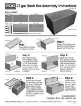
1.9.2 Replacing the Filter Motor, Filter Pump, and Related Components
1. Remove the filter pan and lid from the unit. Drain the frypot into a Shortening Disposal Unit
(SDU) or other appropriate metal container.
DANGER
DO NOT drain more than one full frypot or two split frypots into the SDU at one time.

1-11
2. Disconnect the fryer from the electrical power supply and reposition it to gain access to both the
front and rear.
3. Disconnect the flexlines running to the oil-return manifold at the rear of the fryer as well as the
pump suction flexlines at the end of the filter pan connection (see photos below).
Disconnect flexlines indicated by the arrows.
4. Loosen the nut and bolt that secures the bridge to the oil-return manifold.
5. Remove the cover plate from the front of the motor and disconnect the motor wires.
6. Unplug the pump motor assembly 6-pin connector C-2 and, using a pin pusher, disconnect the
vent vacuum-breaker solenoid (pins 2 and 5) that is attached to the oil return manifold.
7. Remove the two nuts and bolts that secure the front of the bridge to the cross brace and carefully
slide the bridge rearward off the cross brace until its front end can be lowered to the floor. Undo
the single nut holding it in place in back. Be careful not to let the rear of the bridge slip off the
manifold at this point.
8. Get a good grip on the bridge, carefully pull it forward off the oil-return manifold, and lower the
entire assembly to the floor. Once on the floor, pull the assembly out the front of the fryer.
9. When required service has been completed, reverse Steps 6-
12 to reinstall the bridge.
NOTE: The black motor wires go on the top terminal, the
white on the bottom. The pump solenoid valve wires go in
positions 1 and 4 of the 6-pin connector C-2; the vent
vacuum-breaker solenoid valve wires go in positions 2 and 5;
the red/black heater tape wires go into position 3 and the
violet/white wires go into position 6 (see illustration on the
following page).
Rib marks position 1
4
1
5
2
Oil Return Solenoid, Vent Solenoid
and Heater Lead Positions
3
6

1-12
10. Reconnect the unit to the electrical power supply, and verify that the pump is functioning
correctly (i.e., when a filter handle is placed in the ON position, the motor should start and there
should be strong suction at the intake fitting and outflow at the rear flush port.)
11. When proper operation has been verified, reinstall the back panels and the filter pan and lid.
12. Reposition the fryer under the exhaust hood and reconnect it to the electrical power supply to
return the fryer to service.
1.9.3 Replacing the Filter Transformer or Filter Relay
Disconnect the fryer from the electrical power supply. Remove the controller from the fryer to
expose the interior of the component box. The filter transformer and relay are located as shown in
the illustration on the next page. The components are held on by threaded pin studs so that only
removal of the nut is required to replace the component.

1-13
1.10 Interface Board Diagnostic Chart
The following diagram and charts provide ten quick system checks that can be performed using only
a multimeter.
Meter Setting Test Pin Pin Results
12 VAC Power 50 VAC Scale 3 of J2 1 of J2 12-16 VAC
24 VAC Power 50 VAC Scale 2 of J2 Chassis 24-30 VAC
*Probe Resistance R X 1000 OHMS 11 of J2 10 of J2 See Chart
High-Limit Continuity R X 1 OHMS 9 of J2 6 of J2 0 - OHMS
Latch Contactor Coil R X 1 OHMS 8 of J2 Chassis 3-10 OHMS
Heat Contactor Coil R X 1 OHMS 7 of J2 Chassis 11-15 OHMS
* Disconnect 15-Pin harness from the computer/controller before testing the probe circuit.
Diagnostic LED Legend
CMP indicates power from 12V transformer
24V indicates power from 24V transformer
HI (RH) indicates output (closed) from right latch relay
HI (LH) indicates output (closed) from left latch relay (if
present)
HT (RH) indicates output from right heat relay
HT (LH) indicates output from left heat relay (if present)
AL (RH) indicates output (open) from right latch relay
AL (LH) indicates output (open) from left latch relay (if
present)
PN 106-6666
NOTE - When testing on J1 and/or J2, use the
illustration above. Pin 1 is located on the
bottom right corner of both J1 and J2.
Disregard any silk-screened or painted
numbers on the board showing the location
of Pin1.

1-14
1.11 Probe Resistance Chart
Probe Resistance Chart
For use with fryers manufactured with Minco Thermistor probes only.
F OHMS C F OHMS C F OHMS C F OHMS C F OHMS C
60 1059 16 130 1204 54 200 1350 93 270 1493 132 340 1634 171
65 1070 18 135 1216 57 205 1361 96 275 1503 135 345 1644 174
70 1080 21 140 1226 60 210 1371 99 280 1514 138 350 1654 177
75 1091 24 145 1237 63 215 1381 102 285 1524 141 355 1664 179
80 1101 27 150 1247 66 220 1391 104 290 1534 143 360 1674 182
85 1112 29 155 1258 68 225 1402 107 295 1544 146 365 1684 185
90 1122 32 160 1268 71 230 1412 110 300 1554 149 370 1694 188
95 1133 35 165 1278 74 235 1422 113 305 1564 152 375 1704 191
100 1143 38 170 1289 77 240 1432 116 310 1574 154 380 1714 193
105 1154 41 175 1299 79 245 1442 118 315 1584 157 385 1724 196
110 1164 43 180 1309 82 250 1453 121 320 1594 160 390 1734 199
115 1174 46 185 1320 85 255 1463 124 325 1604 163 395 1744 202
120 1185 49 190 1330 88 260 1473 127 330 1614 166 400 1754 204
125 1195 52 195 1340 91 265 1483 129 335 1624 168 405 1764 207

1-15
1.12 Component Wiring
1.12.1 Standard Wiring YFPRE

1-16
1.12.2 Tilt Switch Wiring
1.12.3 Terminal Block Wiring
/