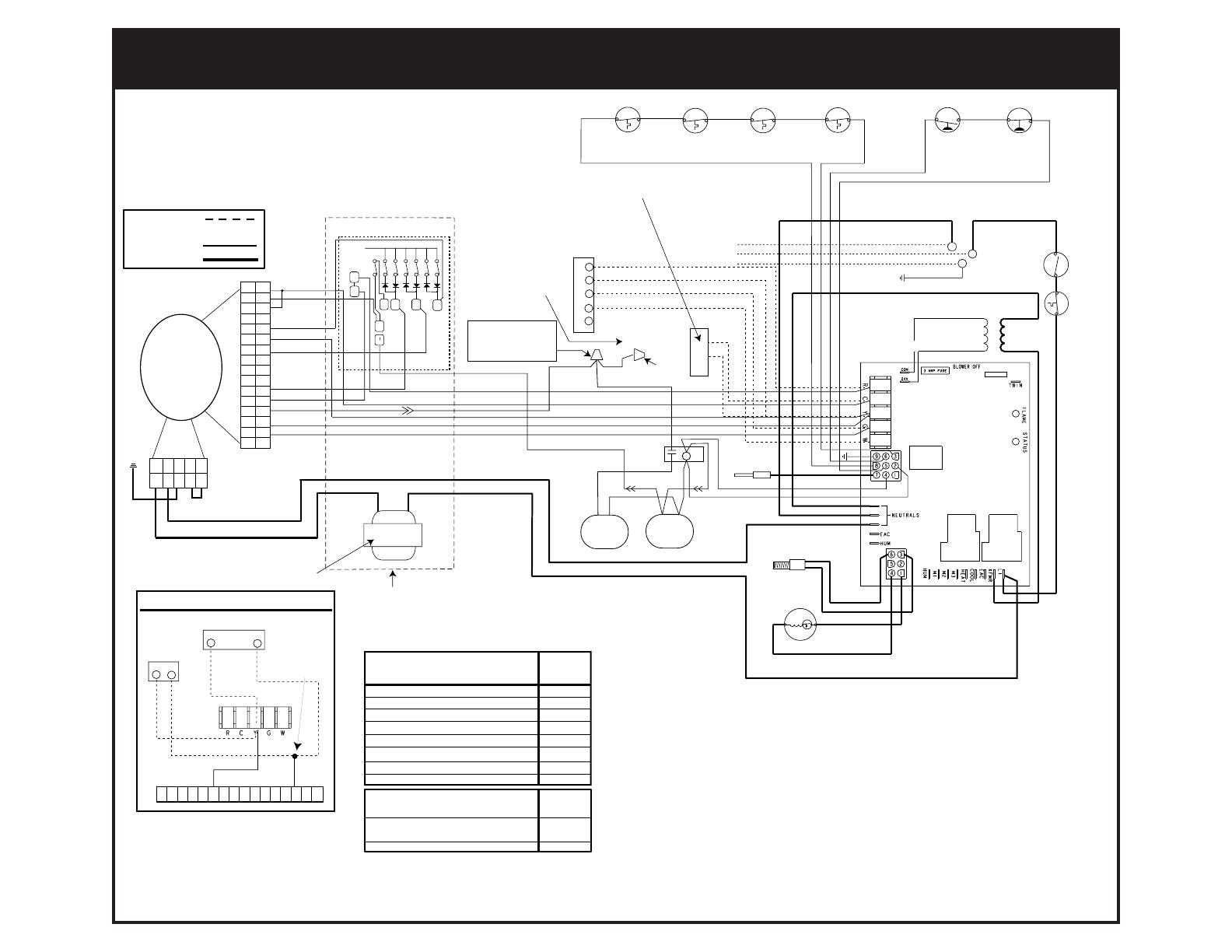
Legend
Field Wiring
Factory Wiring:
Low Voltage
High Voltage
Power On
Limit Circuit Open or External Load On "W"
Pressure Switch is Open with Inducer On
Pressure Switch is Closed with Inducer Off
Ignition Failure (Check Ground)
115 VAC & Neutral Reversed or no Ground
False Flame or Gas Valve Relay Shorted
ON
1 FLASH
2 FLASHES
3 FLASHES
4 FLASHES
5 FLASHES
Continuous
STATUS
RED
LIGHT
FAULT CONDITION
Power Off
Low Flame Sensor Signal
Flame Present
Continuous
Flash
OFF
ON
FLAME
YELLOW
LIGHT
FAULT CONDITION
IGNITOR
INDUCER
PRIMARY
GAS
VALVE
SUPPLY AIR
LIMIT SWITCH
(ALL MODELS)
VENT
SAFETY SWITCH
(ALL MODELS)
TRANSFORMER
FLAME SENSOR
C
GREEN
BLACK
WHITE
BLUE
24 V
120 V
ORANGE
BLUE
BLUE
YELLOW
BROWN
BLACK
ORANGE
BLACK
RED
AIR CONDITIONER
CONDENSING UNIT
BLACK
BLACK
BLOWER DOOR
SWITCH
R
WHITE
BLACK
WHITE W/ BLK STRIPES
BLK W/ WHITE STRIPES
WHITE (NEUTRAL)
BLACK 120V
GROUND
BLACK
BLUE
FLAME ROLL-OUT
SWITCH
(ALL MODELS)
VENT
PRESSURE SWITCH
PRESSURE
SWITCH
(SELECT
MODELS
ONLY)
C
Y
180
120
90
60
TWO STAGE
ROOM THERMOSTAT
R
Y
G
W
W2
SECONDARY
SOLENOID
GAS VALVE
YELLOW
GREEN
YELLOW
GREY
RED
BROWN
YELLOW
BROWN
BLACK
WHITE
BLACK
SEE INSTALLATION
INSTRUCTIONS
FOR ALTERNATE
MEANS OF USING
SECOND STAGE.
BLOWER DECK
LIMIT SWITCH
(SELECT MODELS ONLY)
BLUE
W
W
RED
R
R
13 11 7 5
1234567
GREY
YELLOW
BLUE
BROWN
ORANGE
1
2
3
4
5
6
7
8
9
10
11
12
13
14
15
16
POWER FACTOR
CORRECTION CHOKE
1
2
3
4
5
6
7
8
9
10
11
12
13
14
15
16
12345
VARIABLE
SPEED
BLOWER
MOTOR
12345
VARIABLE SPEED
BLOWER CONTROL BOX
NOTES:
1. Use copper conductors only.
2. If any of the original wire as supplied with the furnace must be
replaced, it must be replaced with wiring material having a
temperature rating of at least 105˚ C.
3. Refer to the Installation Instructions provided with the furnace
for the appropriate heating and cooling speed settings for
your application.
4. Ensure that wires from the blower remain connected to the board
thermostat terminals after making the field thermostat connections.
5. Wiring shown for 2-stage operation when using a multistage thermostat.
Warning - Remove Yellow/Black wire from primary gas valve and utilize
for wiring furnace for 2-stage operation.
WHITE
YELLOW/
BLACK
CLOSED END
CONNECTOR
DO NOT REMOVE!
SEE
NOTE 5
BROWN
(90+ MODELS ONLY)
BROWN
R
BROWN
YELLOW
BLUE
YELLOW
1
2
3
4
5
6
7
8
9
10
11
12
13
14
15
16
Y2
Y1
THERMOSTAT
TWO STAGE CONDENSING UNIT
Y2
Y1
YELLOW
Y1
BLUE
Y2
CONDENSING
UNIT
REMOVE BLUE
WIRE FROM
Y TERMINAL
OF
FURNACE
BOARD
IF TWO STAGE CONDENSING UNIT
IS USED, SEE INSERT A
VENT
SAFETY
SWITCH
(SELECT
MODELS
ONLY)
For 80+ and 90+ 2-Stage Variable Speed
Model Furnaces
710375A (Replaces 7103750)
¢710375+¤
710375A
WIRING DIAGRAM
