Page is loading ...

USER’S MANUAL
Revision 1.0
Desktop
5130DQ-IL

The information in this User’s Manual has been carefully reviewed and is believed to be accurate. The vendor assumes
no responsibility for any inaccuracies that may be contained in this document, and makes no commitment to update
or to keep current the information in this manual, or to notify any person or organization of the updates. Please Note:
For the most up-to-date version of this manual, please see our website at www.supermicro.com.
Super Micro Computer, Inc. ("Supermicro") reserves the right to make changes to the product described in this manual
at any time and without notice. This product, including software and documentation, is the property of Supermicro and/
or its licensors, and is supplied only under a license. Any use or reproduction of this product is not allowed, except
as expressly permitted by the terms of said license.
IN NO EVENT WILL Super Micro Computer, Inc. BE LIABLE FOR DIRECT, INDIRECT, SPECIAL, INCIDENTAL,
SPECULATIVE OR CONSEQUENTIAL DAMAGES ARISING FROM THE USE OR INABILITY TO USE THIS PRODUCT
OR DOCUMENTATION, EVEN IF ADVISED OF THE POSSIBILITY OF SUCH DAMAGES. IN PARTICULAR, SUPER
MICRO COMPUTER, INC. SHALL NOT HAVE LIABILITY FOR ANY HARDWARE, SOFTWARE, OR DATA STORED
OR USED WITH THE PRODUCT, INCLUDING THE COSTS OF REPAIRING, REPLACING, INTEGRATING,
INSTALLING OR RECOVERING SUCH HARDWARE, SOFTWARE, OR DATA.
Any disputes arising between manufacturer and customer shall be governed by the laws of Santa Clara County in the
State of California, USA. The State of California, County of Santa Clara shall be the exclusive venue for the resolution
of any such disputes. Supermicro's total liability for all claims will not exceed the price paid for the hardware product.
FCC Statement: This equipment has been tested and found to comply with the limits for a Class B digital device
pursuant to Part 15 of the FCC Rules. These limits are designed to provide reasonable protection against harmful
interference when the equipment is operated in a commercial environment. This equipment generates, uses, and can
radiate radio frequency energy and, if not installed and used in accordance with the manufacturer’s instruction manual,
may cause harmful interference with radio communications. Operation of this equipment in a residential area is likely
to cause harmful interference, in which case you will be required to correct the interference at your own expense.
California Best Management Practices Regulations for Perchlorate Materials: This Perchlorate warning applies only
to products containing CR (Manganese Dioxide) Lithium coin cells. “Perchlorate Material-special handling may apply.
See www.dtsc.ca.gov/hazardouswaste/perchlorate”.
WARNING: Handling of lead solder materials used in this product may expose you to lead, a
chemical known to the State of California to cause birth defects and other reproductive harm.
The products sold by Supermicro are not intended for and will not be used in life support systems, medical equipment,
nuclear facilities or systems, aircraft, aircraft devices, aircraft/emergency communication devices or other critical
systems whose failure to perform be reasonably expected to result in signicant injury or loss of life or catastrophic
property damage. Accordingly, Supermicro disclaims any and all liability, and should buyer use or sell such products
for use in such ultra-hazardous applications, it does so entirely at its own risk. Furthermore, buyer agrees to fully
indemnify, defend and hold Supermicro harmless for and against any and all claims, demands, actions, litigation, and
proceedings of any kind arising out of or related to such ultra-hazardous use or sale.
Manual Revision 1.0
Release Date: March 09, 2017
Unless you request and receive written permission from Super Micro Computer, Inc., you may not copy any part of this
document. Information in this document is subject to change without notice. Other products and companies referred
to herein are trademarks or registered trademarks of their respective companies or mark holders.
Copyright © 2017 by Super Micro Computer, Inc.
All rights reserved.
Printed in the United States of America

Preface
3
Preface
3
Preface
About this Manual
This manual is written for professional system integrators and PC technicians. It provides
information for the installation and use of the 5130DQ-IL. Installation and maintainance should
be performed by experienced technicians only.
Please refer to the 5130DQ-IL specications page on our website for updates on supported
memory, processors and operating systems (http://www.supermicro.com).
Notes
For your system to work properly, please follow the links below to download all necessary
drivers/utilities and the user’s manual for your system.
• Supermicro product manuals: http://www.supermicro.com/support/manuals/
• Product drivers and utilities: ftp://ftp.supermicro.com
• Product safety info: http://www.supermicro.com/about/policies/safety_information.cfm
If you have any questions, please contact our support team at:
This manual may be periodically updated without notice. Please check the Supermicro website
for possible updates to the manual revision level.
Warnings
Special attention should be given to the following symbols used in this manual.
Warning! Indicates high voltage may be encountered when performing a procedure.
Warning! Indicates important information given to prevent equipment/property damage
or personal injury.

4
Desktop 5130DQ-IL User's Manual
Contents
Chapter 1 Introduction
1.1 Overview ...............................................................................................................................8
1.2 System Features ..................................................................................................................9
1.3 Chassis Features ...............................................................................................................10
Front Features ...................................................................................................................10
Rear Features ...................................................................................................................11
DisplayPort .....................................................................................................................12
HDMI Port ......................................................................................................................12
VESA
®
DisplayPort™ .....................................................................................................12
Back Panel High Denition Audio (HD Audio) ..............................................................12
1.4 Motherboard Layout ...........................................................................................................13
Quick Reference Table ......................................................................................................14
System Block Diagram ......................................................................................................15
Chapter 2 Maintenance and Component Installation
2.1 Removing Power ................................................................................................................16
2.2 Accessing the System ........................................................................................................16
2.3 Installing Hard Drives .........................................................................................................17
2.4 Removing and Installing the Front Bezel ...........................................................................20
2.5 Installing a Peripheral Device ............................................................................................21
2.6 Installing Expansion Cards .................................................................................................22
2.7 Installing the System Fan ...................................................................................................23
2.7 Installing a Power Supply ...................................................................................................24
2.8 Installing a Processor and Heatsink ...................................................................................25
Installing the Processor .....................................................................................................25
Installing the Heatsink .......................................................................................................27
Removing the Heatsink .....................................................................................................28
2.9 Installing Memory ...............................................................................................................29
Memory Support ................................................................................................................29
DIMM Installation ..............................................................................................................29
Removing Memory Modules .............................................................................................29
Memory Population Guidelines ......................................................................................30
2.10 Motherboard Battery .........................................................................................................31

Preface
5
Preface
Chapter 3 Motherboard Connections
3.1 Power Connections ............................................................................................................32
3.2 Headers and Connectors ...................................................................................................33
Control Panel Header ....................................................................................................36
3.3 Rear I/O Ports ....................................................................................................................38
DisplayPort .....................................................................................................................38
HDMI Port ......................................................................................................................38
VESA
®
DisplayPort™ .....................................................................................................38
Back Panel High Denition Audio (HD Audio) ..............................................................38
SPDIF OUT (JSPDIF_OUT) ..........................................................................................38
USB (Universal Serial Bus) Ports ..................................................................................39
3.4 Jumpers ..............................................................................................................................40
Explanation of Jumpers.....................................................................................................40
3.5 LED Indicators ....................................................................................................................42
Chapter 4 Software
4.1 Driver Installation ................................................................................................................43
4.2 SuperDoctor
®
5 ...................................................................................................................44
Chapter 5 BIOS
5.1 Introduction .........................................................................................................................45
Starting BIOS Setup Utility ................................................................................................45
5.2 System Information ............................................................................................................46
How To Change the Conguration Data ...........................................................................46
5.3 CPU ....................................................................................................................................47
5.4 Memory ...............................................................................................................................54
5.5 Advanced ............................................................................................................................55
Boot Features ....................................................................................................................55
NCT6792D Super IO Conguration ..................................................................................57
Serial Port Console Redirection ........................................................................................58
Legacy Console Redirection .............................................................................................60
Legacy Console Redirection Settings ...............................................................................60
System Agent (SA) Conguration .....................................................................................61
PEG Port Conguration.....................................................................................................62
PEG 0:1:0 ..........................................................................................................................62
PEG 0:1:1 ..........................................................................................................................62
PEG 0:1:2 ..........................................................................................................................63

6
Desktop 5130DQ-IL User's Manual
Graphics Conguration......................................................................................................63
PCH-IO Conguration .......................................................................................................66
SATA and RST Conguration ............................................................................................67
PCH FW Conguration ......................................................................................................69
USB Conguration ............................................................................................................70
PCIe/PCI/PnP Conguration .............................................................................................71
Option ROM Execution .....................................................................................................71
PCIe/PCI/PnP Conguration .............................................................................................72
Security .............................................................................................................................73
Secure Boot ......................................................................................................................74
Key Management .............................................................................................................75
5.6 Thermal and Fan ................................................................................................................78
5.7 Save and Exit .....................................................................................................................80
Appendix A BIOS Codes
Appendix B Standardized Warning Statements for AC Systems
Appendix C System Specications
Appendix D UEFI BIOS Recovery/Boot Block

7
Preface
7
Contacting Supermicro
Headquarters
Address: Super Micro Computer, Inc.
980 Rock Ave.
San Jose, CA 95131 U.S.A.
Tel: +1 (408) 503-8000
Fax: +1 (408) 503-8008
Email: [email protected] (General Information)
[email protected] (Technical Support)
Website: www.supermicro.com
Europe
Address: Super Micro Computer B.V.
Het Sterrenbeeld 28, 5215 ML
's-Hertogenbosch, The Netherlands
Tel: +31 (0) 73-6400390
Fax: +31 (0) 73-6416525
Email: [email protected] (General Information)
[email protected] (Technical Support)
[email protected] (Customer Support)
Website: www.supermicro.nl
Asia-Pacic
Address: Super Micro Computer, Inc.
3F, No. 150, Jian 1st Rd.
Zhonghe Dist., New Taipei City 235
Taiwan (R.O.C)
Tel: +886-(2) 8226-3990
Fax: +886-(2) 8226-3992
Email: [email protected]
Website: www.supermicro.com.tw

8
Desktop 5130DQ-IL User's Manual
Chapter 1
Introduction
1.1 Overview
The 5130DQ-IL is a compact desktop system comprised of the DS3A-261B chassis and the
C7Q270-CB-ML single processor motherboard.
Refer to our website for information on operating systems that have been certied for use
with the system (www.supermicro.com).
This chapter provides a brief outline of the functions and features.

9
Chapter 1: Introduction
1.2 System Features
The following table provides an overview of the main features of the 5130DQ-IL.
System Features
Motherboard
C7Q270-CB-ML
Chassis
Mini Tower, DS3A-261B
CPU
Supports Intel 6th/7th Gen Core i7/i5/i3, Pentium or Celeron processor
Socket Type
LGA1151
Chipset
Q270 Express
Memory
Supports up to 64 GB of unbuffered, non-ECC DDR4-2400 memory in four DIMM slots
Expansion Slots
One PCI-E 3.0 x16 slot. one PCI-E 3.0 x4 slot, one PCI-E 3.0 x1 slot and one PCIe 3.0 x4 M.2 (supports 2280)
Drive Bays
Two 5.25" external drive bays, one 3.5" external drive bay, two internal xed 3.5" drive bays, one internal xed
2.5" drive bay
Fan
One rear 8-cm fan
Power
One 260W ATX power supply
Input/Output Ports
One Gigabit LAN port
Six USB3.0 ports and four USB2.0 ports
One DisplayPort, one HDMI, one DVI-D
Six SATA3 (6Gbps) ports
One COM port header
One mouse/keyboard combo port
Dimensions
Width 6.89" (175mm), Height 14.65" (372mm), Depth 16.85" (428mm)

10
Desktop 5130DQ-IL User's Manual
Front Chassis Features
Item Feature Description
1 USB Port USB 3.0 port
2 USB Port USB 3.0 port
3 Mic Microphone jack
4 Audio Audio out jack
5 USB Port USB 2.0 port
6 USB Port USB 2.0 port
7 NIC LED Indicates network activity when ashing
8 HDD LED Indicates network activity when ashing
9 Power Button This LED alerts the operator to several states, as noted in the table below.
Figure 1-1. Chassis Front View
1.3 Chassis Features
Front Features
The DS3A-261B is a compact Mini Tower chassis. The front of the chassis includes a power
on/off push-button and several LEDs as described below.
7
6
5
43
8
9
1
2

11
Chapter 1: Introduction
Figure 1-2. Rear I/O Ports
Rear I/O Ports
# Description # Description # Description
1. PS2 Keyboard/Mouse Port 7 USB4 Port (USB 3.0) 13 Surround Out
2. USB0 Port (USB 2.0) 8 USB5 Port (USB 3.0) 14 SPDIF Out
3 USB1 Port (USB 2.0) 9 RJ-45 Gb Ethernet Port 15 Line In
4 Display Port 10 USB6 Port (USB 3.0) 16 Line Out
5 HDMI Port 11 USB7 Port (USB 3.0) 17 Mic In
6. DVI-D Port 12 Center/LFE Out
1
9
8
7
6
5
4
3
2
10
11
12
14
13
15
17
16
Rear Features
The rear of the chassis has various input/output ports.
Note: See Chapter 3 for pin dentions of the USB ports.

12
Desktop 5130DQ-IL User's Manual
DisplayPort
DisplayPort, develped by the VESA consortium, delivers digital display and fast refresh rates.
It can connect to virtually any display device using a DisplayPort adapter for devices such
as VGA, DVI or HDMI.
HDMI Port
The HDMI (High-Denition Multimedia Interface) port is used to display both high denition
video and digital sound through an HDMI-capable display, using the same (HDMI) cable.
VESA
®
DisplayPort™
DisplayPort, develped by the VESA consortium, delivers digital display at a fast refresh rate.
It can connect to virtually any display device using a DisplayPort adapter for devices such
as VGA, DVI or HDMI.
Back Panel High Denition Audio (HD Audio)
This motherboard features a 7.1+2 Channel High Denition Audio (HDA) codec that provides
10 DAC channels. The HD Audio connections simultaneously supports multiple-streaming
7.1 sound playback with two channels of independent stereo output through the front panel
stereo out for front, rear, center and subwoofer speakers.

13
Chapter 1: Introduction
1.4 Motherboard Layout
Jumper, connector and LED locations are shown below with brief descriptions on the following
page. Detailed descriptions are found in Chapter 3.
Figure 1-3. Motherboard Layout
• Jumpers and LED indicators not identied are used for testing only.
• " " indicates the location of pin 1.
TPM/PORT80JTPM1:
JTPM1
RST
PWR
ON
XOH/FF
X
NIC
1
PWR
LED
HDD
LED
JF1
USB 2/3USB 8/9(3.0)
2-3:BIOS RECOVERY
1-2:NORMAL
JBR1
WATCH DOG
1-2:RST
2-3:NMI
JWD1:
JBR1
JPME2
AUDIO FP
COM1
JD1:SPEAKER :1-4
JD1
JSD1
JWD1
JL1
JSD1:SATA DOM PWR
JL1:
CHASSIS
INTRUSION
2-3:ME MANUFACTURING MODE
JPME2:
1-2:NORMAL
I-SATA5
I-SATA4
I-SATA3
I-SATA2
I-SATA1
I-SATA0
PCH SLOT1 PCI-E 3.0 X1
JBT1
JBT1:CMOS CLEAR
PCH SLOT2 PCI-E 3.0 X4
CMOS
BUTTON
BUTTON
CLEAR
POWER
RESET
J9702
JSTBY1
J9701
JI2C1
JI2C2
JSPDIF_OUT
5V STBY POWER
JSTBY1:
CPU SLOT3 PCI-E 3.0 X16
OFF:DISABLE
JI2C1/JI2C2
ON :ENABLE
HD AUDIO
PCIE M.2
CONNECTOR 1
SYS_FAN2
USB 6/7(3.0)
LAN
CPU
JPW1
DVI
JPUSB1:USB0/1 WAKE UP
HDMI/DP
DIMMB2
DIMMA2
DIMMB1
DIMMA1
2-3 DISABLE
1-2 ENABLE
CPU_FAN1
JVR1
JPUSB1
JPW2
KB/MOUSE
LED1
RT1
REV: 1.01
C7Q270-CB-ML
DESIGNED IN USA
+
MAC CODE
BAR CODE
BIOS LICENSE
C
A
+
A C
USB 4/5(3.0)
USB 0/1
B1
2280
2260
2242
SYS_FAN1

14
Desktop 5130DQ-IL User's Manual
Quick Reference Table
Jumper Description Default Setting
JBR1 BIOS Recovery Pins 1-2: (Normal)
JBT1 Clear CMOS (onboard) Open: Normal, Short: Clear CMOS
JI2C1/JI2C2 SMB to PCI-E Slots Enable/Disable On: (Enable)
JPME2 Intel Manufacturing Mode Pins 1-2: (Normal)
JPUSB1 USB Wake Up (USB 0/1) Enable/Disable Pins 1-2: (Enable)
JWD1 Watch Dog Function Enable Pins 1-2: (Reset)
LED Description Status
LED1 Power LED S3 Blink Function Blinking Green: S3 function
Connector Description
AUDIO FP Front Panel Audio Header
BT1 Onboard Battery
COM1 COM1 Port Header
CPU_FAN1 CPU Fan Headers
I-SATA0~5 (Intel PCH) Serial ATA (SATA) 3.0 Ports 0~5
JD1 Pins 1~4: External Speaker
JF1 Front Panel Control Header
JL1 Chassis Intrusion Header
JPW1 24-pin ATX Power Connector
JPW2 8-pin CPU Power Connector
JSD1 SATA DOM (Disk On Module) Power Connector
JSPDIF_OUT S/PDIF (Sony/Philips Digital Interface) Out Header
JSTBY1 Standby Power Header
JTPM1 Trusted Platform Module (TPM) Header
PCI-E M.2 Connector 1 PCI-E M.2 Connector
SYS_FAN1/FAN2 System Fan Headers
USB 2/3 Front Accessible USB 2.0 Headers
USB 8/9 (3.0) Front Accessible USB 3.0 Headers

15
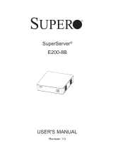
Chapter 1: Introduction
Figure 1-4. System Block Diagram
Note: This is a general block diagram and may not exactly represent the features on your
motherboard.
System Block Diagram
DDI 1
DDI 2
DDI 3
2 X USB 2.0 Rear
480Mbps
USB2.0
2 X USB 2.0 Header
480Mbps
USB2.0
2400/2133/1866MHz
IMVP8
INTEL LGA1151
PCIe3.0_x16
8.0GT/s
SVID
IMVP8
DDR4 (CHA)
DIMMA0
DDR4 (CHB)
DIMMB0
2400/2133/1866MHz
8GT/s
x4 DMI
RJ45
8GT/s
PCIe3.0_x1
GLAN1
I219LM-Q270
Intel
PCH-H
Q270
(Socket-H4)
AZALIA
Realtek
ALC1150
FLASH
SPI 128Mb
SPI
DVI
Display Port
HDMI
DDI1
DDI2
DDI3
LPC
DIMMA1
DIMMB1
TPM 2.0 Header
COM1 Header
NCT6792D-B
LPC I/O
PCIe x8(in x16) SLOT #6
or
PCIe x16 SLOT #6
PCIe3.0_x8
8.0GT/s
1 X M.2 SOCKET SSD
8GT/s
PCIe3.0_x4
PCIe x1 SLOT Rear
8GT/s
PCIe3.0_x1
USB3.0
5Gbps
2 X USB 3.0 Rear
2 X USB 3.0 Header
5Gbps
USB3.0
PS2 KB/MS
6X SATA-III
SATA-III
6Gb/s
Audio Jack/ Audio Pin Header
PCIe x4 SLOT Rear
PCIe3.0_x4
8GT/s
2 X USB 3.0 Rear
USB3.0
5Gbps

16
Desktop 5130DQ-IL User's Manual
Chapter 2
Maintenance and Component Installation
This chapter provides instructions on installing and replacing main system components. To
prevent compatibility issues, only use components that match the specications and/or part
numbers given.
Installation or replacement of most components requires that power rst be removed from
the system. Please follow the procedures given in each section.
2.1 Removing Power
Use the following procedure to ensure that power has been removed from the system. This
step is necessary when removing or installing non hot-swap components or when replacing
a non-redundant power supply.
1. Use the operating system to power down the system.
2. After the system has completely shut-down, disconnect the AC power cord from the
power source.
3. Disconnect the power cord from the chassis.
2.2 Accessing the System
The DS3A-261B features a removable top cover to access to the inside of the chassis.
Removing the Chassis Cover
1. Power down the system and remove the power cord from the rear of the power supply
as described in Section 2.1.
2. Slide the release tab downward.
3. Grasp the cover and lift it off the chassis.
Caution: Except for short periods of time, do not operate the system without the cover in
place. The chassis cover must be in place to allow proper airow and prevent overheating.

17
Chapter 2 Maintenance and Component Installation
Figure 2-1. Removing the Chassis Cover
2.3 Installing Hard Drives
Removing and Installing Hard Drives
1. Power down the system and remove the power cord from the rear of the power supply
as described in Section 2.1 and remove the chassis cover as described in Section 2.2.
2. Disconnect all of the cables from the hard drive.
3. Press the release tab on the side of the hard drive carrier that is to be removed from the
hard drive bay.
4. Gently slide the hard drive carrier out of the hard drive bay.
Release
Tab
3

18
Desktop 5130DQ-IL User's Manual
Release
Tab
4
3
Figure 2-2. Removing a Hard Drive Carrier from the Chassis
Figure 2-3. Removing a Hard Drive from a Hard Drive Carrier
6
5
5
5. If a hard drive or dummy drive is present, simultaneiously pull both sides of the hard
drive carrier open and lift the drive out.
6. Insert the new hard drive into the hard drive carrier by simultaneously pulling both sides
of the drive carrier open and placing the drive into the carrier.

19
Chapter 2 Maintenance and Component Installation
Figure 2-4. Installing the Hard Drive Carrier into the Hard Drive Bay
7. Insert the hard drive carrier into the hard drive bay, sliding it towards the back of the the
hard drive bay until it clicks into a locked position.
8. Connect the cables to the hard drives, plug the power cord into the rear of the power
supply, replace the chassis cover and power up the system.
7

20
Desktop 5130DQ-IL User's Manual
2.4 Removing and Installing the Front Bezel
Front Bezel Removal
1. Power down the system and remove the power cord from the rear of the power supply
as described in Section 2.1 and remove the chassis cover as described in Section 2.2.
2. Remove the front bezel by pulling the release tabs outward, and then pulling the bezel
off the front of the chassis.
Front Bezel Installation
1. Replace the chassis bezel by inserting the tabs on the right side of the bezel into their
mounting holes on the chassis.
2. Close the bezel so that the release tabs click into their locked positions on the left side
of the chassis.
Figure 2-6. Installing the Front Bezel
Figure 2-5. Removing the Front Bezel
Release Tabs
Peripheral Drive
Bay Covers
2
2
/