Page is loading ...

Installation manual
EPCT Fire series Fire Pump Controller

ii
EPCT FIRE SERIES FIRE PUMP CONTROLLER MN124016EN August 2019 www.eaton.com
DISCLAIMER OF WARRANTIES AND LIMITATION OF LIABILITY
The information, recommendations, descriptions and safety notations in this document are based on Eaton Corporation’s
(“Eaton”) experience and judgment and may not cover all contingencies. If further information is required, an Eaton sales
office should be consulted. Sale of the product shown in this literature is subject to the terms and conditions outlined in
appropriate Eaton selling policies or other contractual agreement between Eaton and the purchaser.
THERE ARE NO UNDERSTANDINGS, AGREEMENTS, WARRANTIES, EXPRESSED OR IMPLIED, INCLUDING WARRANTIES
OF FITNESS FOR A PARTICULAR PURPOSE OR MERCHANTABILITY, OTHER THAN THOSE SPECIFICALLY SET OUT IN ANY
EXISTING CONTRACT BETWEEN THE PARTIES. ANY SUCH CONTRACT STATES THE ENTIRE OBLIGATION OF EATON. THE
CONTENTS OF THIS DOCUMENT SHALL NOT BECOME PART OF OR MODIFY ANY CONTRACT BETWEEN THE PARTIES.
In no event will Eaton be responsible to the purchaser or user in contract, in tort (including negligence), strict liability or
other-wise for any special, indirect, incidental or consequential damage or loss whatsoever, including but not limited to
damage or loss of use of equipment, plant or power system, cost of capital, loss of power, additional expenses in the use of
existing power facilities, or claims against the purchaser or user by its customers resulting from the use of the information,
recommendations and descriptions contained herein. The information contained in this manual is subject to change without
notice.

iii
Index
EPCT FIRE SERIES FIRE PUMP CONTROLLER MN124016EN August 2019 www.eaton.com
Index
1.0 Introduction 1
1.1 Safety .......................................................................................................................................................................... 1
1.2 Warranty ......................................................................................................................................................................1
1.3 Safety precautions ......................................................................................................................................................1
1.4 Product overview ........................................................................................................................................................1
2.0 Installation and electrical connections 2
2.1 Mounting ....................................................................................................................................................................2
2.2 Pressure switch connections .....................................................................................................................................2
2.3 Electrical connections .................................................................................................................................................2
2.3.1 Wire sizes ..............................................................................................................................................2
2.3.2 Electrical checkout instructions .............................................................................................................. 2
3.0 Hardware description 4
3.1 General .......................................................................................................................................................................4
3.2 Display board ..............................................................................................................................................................4
3.2.1 Memory .................................................................................................................................................4
3.2.2 Battery backup .......................................................................................................................................4
3.2.3 Color touchscreen specifications ...........................................................................................................4
3.2.4 USB port ................................................................................................................................................4
3.3 Power I/O board .........................................................................................................................................................4
3.4 ATS board (if equipped) ..............................................................................................................................................4
3.5 Main isolating switch/circuit interrupter .....................................................................................................................4
3.6 Contactor(s) ................................................................................................................................................................4
3.7 External pushbuttons ..................................................................................................................................................5
3.8 Transfer switch components .......................................................................................................................................5
4.0 Operation 6
4.1 General .......................................................................................................................................................................6
4.2 Welcome screen .........................................................................................................................................................6
4.2.1 Welcome screen and home screen graphics ........................................................................................6
4.2.1.1. Welcome screen ......................................................................................................................................................6
4.2.1.2 Home Tab without an ATS ........................................................................................................................................7
4.2.1.3. Home screen of a controller without an ATS (motor running) ................................................................................8
4.3 Automatic start / stop .................................................................................................................................................8
4.3.1 Manual start sequence ..........................................................................................................................8
4.3.2 Automatic start sequence ...................................................................................................................... 9
4.4 Control inputs .............................................................................................................................................................9
4.4.1 Control input descriptions ......................................................................................................................9
4.4.1.1. Remote manual start ...............................................................................................................................................9
4.4.1.2. Remote manual stop ...............................................................................................................................................9
4.4.1.3. Remote manual start/stop ......................................................................................................................................9
4.4.1.4. Remote auto start ...................................................................................................................................................9
4.4.1.5. Deluge valve start ...................................................................................................................................................9

iv
Index
EPCT FIRE SERIES FIRE PUMP CONTROLLER MN124016EN August 2019 www.eaton.com
4.4.1.6. Low suction .............................................................................................................................................................9
4.4.1.7. Low foam level .........................................................................................................................................................9
4.4.1.8. Proof pressure switch .............................................................................................................................................9
4.4.1.9. Low room temperature ...........................................................................................................................................9
4.4.1.10. High room temperature .........................................................................................................................................9
4.4.1.11. Interlock................................................................................................................................................................10
4.4.1.12. Low reservoir ......................................................................................................................................................10
4.4.1.13. High reservoir ......................................................................................................................................................10
4.4.1.14. Go to source 1.....................................................................................................................................................10
4.4.1.15. Go To Source 2 ....................................................................................................................................................10
4.4.1.16. Enable Sequential Start .......................................................................................................................................10
4.5 Output relays ............................................................................................................................................................ 10
4.5.1 Startup (1CR) ........................................................................................................................................ 10
4.5.2 Acceleration (2CR) ................................................................................................................................ 10
4.5.3 Common alarm (3CR) ........................................................................................................................... 10
4.5.4 Power / phase failure (4CR) .................................................................................................................. 10
4.5.5 Phase reversal (5CR) ............................................................................................................................ 10
4.5.6 Pump run (6CR) .................................................................................................................................... 10
5.0 Programming 11
5.1 Introduction .............................................................................................................................................................. 11
5.2 Navigation ................................................................................................................................................................. 11
5.3 Startup tab ................................................................................................................................................................ 12
5.3.1 Quick setup ..........................................................................................................................................12
5.3.2 Setup phase reversal ............................................................................................................................ 12
5.3.3 Flow test ..............................................................................................................................................13
5.3.4 Manual/Automatic start ........................................................................................................................13
5.3.5 Test alarm ............................................................................................................................................. 13
5.3.6 USB download .....................................................................................................................................13
5.4 Panel setup tab .........................................................................................................................................................13
5.4.1 Language .............................................................................................................................................. 13
5.4.2 Set time ...............................................................................................................................................13
5.4.3 Set date ................................................................................................................................................13
5.4.4 Set day of the week ............................................................................................................................. 13
5.4.5 Starting method ................................................................................................................................... 13
5.4.6 Single phase start ................................................................................................................................ 13
5.4.7 Auto shutdown ..................................................................................................................................... 13
5.4.8 Controller HP ........................................................................................................................................13
5.4.9 Nominal voltage ...................................................................................................................................13
5.4.10 Phases .................................................................................................................................................. 14
5.4.11 System frequency ................................................................................................................................ 14
5.4.12 CT Ratio................................................................................................................................................14
5.4.13 Motor FLA ............................................................................................................................................ 14
5.4.14 Common alarm settings ....................................................................................................................... 14
5.4.15 Notification area settings ..................................................................................................................... 14

v
Index
EPCT FIRE SERIES FIRE PUMP CONTROLLER MN124016EN August 2019 www.eaton.com
5.4.16 Foam controller .................................................................................................................................... 14
5.4.17 Menu password ...................................................................................................................................14
5.4.18 Controller serial number .......................................................................................................................14
5.4.19 Pump serial number ............................................................................................................................. 14
5.4.20 Save configuration to USB ................................................................................................................... 14
5.4.21 Load configuration to USB ................................................................................................................... 14
5.4.22 Save settings as factory default ........................................................................................................... 14
5.4.23 Restore factory default settings ...........................................................................................................14
5.4.24 Screen brightness ................................................................................................................................14
5.4.25 Welcome screen .................................................................................................................................. 14
5.4.26 Screen lock ........................................................................................................................................... 14
5.4.27 Customer service contact .................................................................................................................... 14
5.4.27.1. Save configuration ...............................................................................................................................................14
5.4.27.2 Load configuration ................................................................................................................................................15
5.4.28 Update firmware ..................................................................................................................................15
5.4.29 Update languages ................................................................................................................................15
5.5 Help tab .................................................................................................................................................................... 15
5.5.1 Product manual ....................................................................................................................................15
5.5.2 Service contact information ................................................................................................................. 15
5.5.3 Factory contact information .................................................................................................................15
5.6 Pressure settings tab ............................................................................................................................................... 15
5.6.1 Start pressure ...................................................................................................................................... 15
5.6.2 Stop pressure .......................................................................................................................................15
5.6.3 Low pressure alarm ............................................................................................................................. 15
5.6.4 High pressure alarm .............................................................................................................................15
5.6.5 Start above pressure ............................................................................................................................ 15
5.6.6 Pressure variance recording ................................................................................................................. 15
5.6.7 Hourly pressure recording ....................................................................................................................15
5.6.8 Low suction shutdown ......................................................................................................................... 15
5.6.9 Low foam shutdown ............................................................................................................................16
5.6.10 Proof pressure switch ..........................................................................................................................16
5.6.11 Pressure units ......................................................................................................................................16
5.6.12 Pressure transducer ............................................................................................................................. 16
5.6.13 Calibrate transducer .............................................................................................................................16
5.7 Timer values tab ....................................................................................................................................................... 16
5.7.1 Minimum run time (RPT) ......................................................................................................................16
5.7.2 Acceleration timer (AT) ......................................................................................................................... 16
5.7.3 Sequential start time ............................................................................................................................ 16
5.7.4 Fail to start timer (FTS) ........................................................................................................................16
5.7.5 Fail to stop timer .................................................................................................................................. 16
5.7.6 Weekly motor test timer ...................................................................................................................... 17
5.8 Alarm setpoints tab .................................................................................................................................................. 17
5.8.1 Phase reversal ...................................................................................................................................... 17
5.8.2 Phase failure alarm setpoint .................................................................................................................17
5.8.3 Motor overload setpoint ....................................................................................................................... 17

vi
Index
EPCT FIRE SERIES FIRE PUMP CONTROLLER MN124016EN August 2019 www.eaton.com
5.8.4 Transducer fail pump start.................................................................................................................... 17
5.8.5 Abort motor test on low voltage .......................................................................................................... 17
5.8.6 Voltage alarm settings .......................................................................................................................... 17
5.8.7 Frequency alarm settings ..................................................................................................................... 17
5.9 Inputs/outputs tab .................................................................................................................................................... 17
5.9.1 Inputs ................................................................................................................................................... 17
5.9.2 Outputs ................................................................................................................................................ 17
5.10 History stats diag. Tab (history statistics diagnostics) ............................................................................................ 18
5.10.1 Message history ..................................................................................................................................18
5.10.2 Controller statistics .............................................................................................................................. 18
5.10.3 Controller diagnostics ..........................................................................................................................19
5.10.4 Startup information ..............................................................................................................................19
5.10.5 Save to USB ......................................................................................................................................... 19
6.0 Automatic transfer switch (ATS) 20
6.1 General .....................................................................................................................................................................20
6.2 Main contacts ...........................................................................................................................................................20
6.3 ATS electrical control circuit .....................................................................................................................................20
6.4 Mechanical transfer mechanism ...............................................................................................................................20
6.5 ATS control board & touchscreen display .................................................................................................................21
6.5.1 Inputs ...................................................................................................................................................21
6.5.2 Outputs ................................................................................................................................................21
6.5.3 Touchscreen display ATS graphics .......................................................................................................21
6.6 Programming ............................................................................................................................................................21
6.6.1 Time delay S1 to S2 .............................................................................................................................21
6.6.2 Time delay S2 to S1 .............................................................................................................................21
6.6.3 Time delay neutral ................................................................................................................................ 21
6.6.4 Time delay engine start .......................................................................................................................21
6.6.5 Time delay S2 fail ................................................................................................................................. 21
6.6.6 Time delay engine cooldown ...............................................................................................................21
6.6.7 Dual utility ............................................................................................................................................21
6.6.8 Weekly engine test timer .....................................................................................................................22
7.0 Optional add-on boards 23
7.1 Relay output board ....................................................................................................................................................23
7.1.1 Programming .......................................................................................................................................23
7.2 Secondary 4-20 mA device .......................................................................................................................................23
7.2.1 Programming: .......................................................................................................................................23
7.3 MODBUS Board ....................................................................................................................................................... 23
7.3.1 Programming: .......................................................................................................................................23
7.3.2 MODBUS dip switch settings .............................................................................................................23
7.4 Supervisory alarm option board ................................................................................................................................23
7.4.1 Programming: .......................................................................................................................................23

vii
Index
EPCT FIRE SERIES FIRE PUMP CONTROLLER MN124016EN August 2019 www.eaton.com
Appendix A: menu structure ..............................................................................................................................................24
Appendix B: startup tab menu structure ........................................................................................................................ 25
Appendix C (a): panel setup tab menu structure .........................................................................................................26
Appendix C (b): panel setup tab menu structure continued .....................................................................................27
Appendix C (c): panel setup tab menu structure continued .....................................................................................28
Appendix C (d): panel setup tab menu structure continued ...................................................................................29
Appendix C (e): panel setup tab menu structure continued ..................................................................................... 30
Appendix D: help tab menu structure .............................................................................................................................31
Appendix E (a): pressure settings tab menu structure, .............................................................................................. 32
Appendix E (b): pressure settings tab menu structure continued, ........................................................................33
Appendix E (c): pressure settings tab menu structure continued ........................................................................... 34
Appendix F: timer values tab menu structure .............................................................................................................35
Appendix G (a): ATS settings tab menu structure .......................................................................................................36
Appendix G (b): ATS settings tab menu structure continued ................................................................................... 37
Appendix H (a): alarm setpoints tab menu structure .................................................................................................38
Appendix H (b): alarm setpoints tab menu structure continued .............................................................................39
Appendix I (a): inputs / outputs tab menu structure .................................................................................................40
Appendix I (b): inputs / outputs tab menu structure continued .............................................................................41
Appendix J: History stats diag. Tab menu structure....................................................................................................42
Appendix K: Relay option board– tab menu structure ...............................................................................................43
Appendix L (a): 4-20 mA device – tab menu structure ...............................................................................................44
Appendix L (b): 4-20 mA device – tab menu structure continued .........................................................................45
Appendix M: MODBUS board – tab menu structure ...................................................................................................46
Appendix N: Supervisory alarm option board – tab menu structure .....................................................................47
Appendix O: Alarm/Status messages ............................................................................................................................48
Appendix P: I/O board error codes ...................................................................................................................................50
Appendix Q: Power wire cable reference ......................................................................................................................51

1
Introduction
EPCT FIRE SERIES FIRE PUMP CONTROLLER MN124016EN August 2019 www.eaton.com
1.0 Introduction
1.1 Safety
This technical document is intended to cover most aspects
associated with the installation, application, operation,
and maintenance of the EPCT Fire Pump Controller. It is
provided as a guide for authorized and qualified personnel
only in the selection and application of the EPCT Controller.
If further information is required by the purchaser regarding
particular installation, application, or maintenance activity,
please contact an authorized EATON sales agent or the
installing contractor.
1.2 Warranty
No warranties, expressed or implied, including warranties
of fitness for a particular purpose of merchantability, or
warranties arising from course of dealing or usage of trade,
are made regarding the information, recommendations
and descriptions contained herein. In no event will EATON
be responsible to the purchaser or user in contract, in tort
(including negligence), strict liability or otherwise for any
special, indirect, incidental or consequential damage or loss
whatsoever, including but not limited to damage or loss of
use of equipment, plant or power system, cost of capital,
loss of power, additional expenses in the use of existing
power facilities, or claims against the purchaser of user by
its customers resulting from the use of the information and
descriptions contained herein.
1.3 Safety precautions
All safety codes, safety standards, and/or regulations must
be strictly observed in the installation, operation, and
maintenance of this device.
CAUTION
Completely read and understand the material presented
in this document before attempting installation, operation,
or application of the equipment. In addition, only qualified
persons should be permitted to perform any work
associated with this equipment. Any wiring instructions
presented in this document must be followed precisely.
Failure to do so could cause permanent equipment damage.
1.4 Product overview
The EPCT Controller is a comprehensive, multi-function
microprocessor-based Fire Pump Controller.
Designed to meet the needs of markets worldwide, the
EPCT controller meets the requirement of and is certified
by the following authorities: Underwrites Laboratories (UL),
Underwriters Laboratories of Canada (ULC), Complies with
UL 218 & UL 1008 (if equipped with an Automatic Transfer
Switch (ATS)), Factory Mutual 1321/1323 (FM), ANSI/NFPA
20, Article 695 of ANSI/NFPA 70, National Electrical Code
(NEC), Canadian Standards Association (CSA), CSA-C22.2
standard for Fire Pump Controllers and Automatic Transfer
Switches, and meets the requirements for U.S.B. / C.B.C
Seismic approvals. Starting types of the EPCT Fire Pump
Controller include the following: FD/FT30-Across the Line,
FD/FT40-Part Winding, FD/FT50-Primary Resistor, FD/
FT60-Autotransformer, FD/FT70-Wye-Delta (Star-Delta) Open
Transition, FD/FT80-Wye-Delta (Star-Delta) Closed Transition,
FD/FT90-Soft Start, and FDM30-Medium Voltage Across the
Line. All products, except the FDM30, can be offered as an
Additive (Foam) system and/or with an Automatic Power
Transfer Switch.
The rated impulse withstand voltage rating of this assembly
is 10kV.

2
Installation and electrical connections
EPCT FIRE SERIES FIRE PUMP CONTROLLER MN124016EN August 2019 www.eaton.com
2.0 Installation and electrical connections
2.1 Mounting
Carefully unpack the controller and inspect thoroughly.
The controller should be located as close as is practical to
the motor it controls and shall be within sight of the electric
motor, preferably ten feet or less.
The EPCT controller is designed for either wall or floor
mounting; use Grade 5 bolts. Note that the controller is
not free standing and must be mounted with feet or bolted
securely to a wall. For dimensional and weight data please
refer to the respective data sheets for the various types of
Fire Pump Controllers.
2.2 Pressure switch connections
NOTICE
Water lines to the pressure switch must be free from dirt
and contamination
The EPCT is equipped with a pressure sensor. The controller
is provided with a 1/2” NPT female system pressure
connection located on the bottom, external side of the
enclosure. The connection should be installed as per NFPA,
pamphlet no. 20.
The actual pressure is displayed on the main display. Precise
start and stop pressure set points can be programmed in the
controller. Refer to Section 5 for programming instructions.
The maximum operating pressure of the pressure sensor
and internal plumbing components is listed on the
controller nameplate.
2.3 Electrical connections
NOTICE
All conduit connections to the controller are recommended
to be installed on the bottom of the controller. Refer to the
assoicated dimensional drawing for reference. Drilling or
installing conduit above the microprocessor boards may
void warranty.
All electrical connections should meet national and local
electrical codes and standards.
The controller should be located or so protected that it will
not be damaged by water escaping from pumps or pump
connections. Current carrying parts of controllers shall be a
minimum of 12 inches (305mm) above the floor.
Prior to starting, verify all data on the nameplate such as:
catalog number, AC line voltage, horsepower, and frequency.
Inspect all electrical connections, components, and wiring
for any visible damage. Correct as necessary. Ensure that all
electrical connections are tightened before energizing.
Refer to the wiring schematic affixed to the enclosure door
for all wiring information pertaining to the incoming AC
power supply and motor wiring.
Install necessary conduit using proper methods and tools.
Recommend entry point is on the bottom of the enclosure.
Incoming AC line voltage is clearly marked L1, L2, L3, and
ground, located at the top of the enclosure.
2.3.1 Wire sizes
For control wiring, use #14 AWG wire for all electrical
connections.
For power wiring sizes refer to Appendix Q.
2.3.2 Electrical checkout instructions
The EPCT controller is designed to be phase sensitive. L1,
L2 & L3 should be connected to A, B & C respectively.
Energize the controller by closing the isolation switch
(MIS) and circuit breaker (CB). If the phases are connected
incorrectly, the ‘Phase Reversal’ alarm and graphic will be
displayed on the screen. To correct this condition, refer to
Appendix H to correct the phase reversal setting.
The EPCT has a phase reversal setup procedure that guides
the user through a step by step process to program the
phase rotation. With the controller energized, operate the
‘Bump Motor’ feature through the Setup Phase Reversal in
the Startup tab on the display to check the rotation of the
motor. If the rotation is incorrect, disconnect power and
reverse the connection of the load terminals of the motor
contactor T1, T2 & T3. If the controller is equipped with an
automatic transfer switch (ATS), the guide will prompt the
user to start the generator, transfer and bump the motor.
ote:N On models Primary Resistor (FD/FT40), Wye Delta
(Star-Delta) Open (FD/FT70) and Wye Delta (Star-
Delta) Closed (FD/FT80) models, the connection
must be changed on both contactors, 1M and 2M.
Adjust the pressure set points detailed in Appendix E.
With the controller isolated and the ‘Start Pressure’ and
‘Stop Pressure’ values programmed, energize the controller.
If the system water pressure is lower than the start
pressure, the controller will start the pump. If the controller
is set up for fully automatic operation, the controller will
stop the pump when the pressure is above the stop point
and the running period timer (RPT) has completed its timed
interval. The system pressure must be equal to or greater
than the programmed stop pressure value, otherwise the
pump will stop only when the pushbutton is pushed. If the
controller is not setup for automatic shutdown operation
(programmed for manual stop mode), the stop pushbutton
must be operated to stop the pump.
The circuit breaker setting is factory set and should not
be adjusted.
If required, the running period timer (RPT) must be set
for a minimum of ten (10) minutes. Refer to Appendix F
for programming of the RPT.

3
Installation and electrical connections
EPCT FIRE SERIES FIRE PUMP CONTROLLER MN124016EN August 2019 www.eaton.com
If the sequential start timer (SST) is required refer to
Appendix F. If not required set the SST to disabled. If
required, the lead pump SST should be set to disabled and
the lag SST to five (5) to ten (10) seconds. If there are more
than two pumps in the system, allow a ten (10) second
delay between pumps.
The acceleration timer (AT) is used for reduced in-rush
current controllers only. The AT will be factory set but will
automatically adjust depending on the starting method that
the controller is programmed to. If it is found that more
time is required to allow the pump to come up to speed,
the timer may be adjusted up to 10 seconds. Refer to
Appendix F for programming of the AT.
If the Undervoltage/Overvoltage alarms are present, check
the programmed values by referring to Appendix H. If the
values are programmed to their maximum and the alarms
continue to occur, check the main voltage supply to ensure
that the power available is dependable as per NFPA,
Pamphlet 20 standards.

4
Hardware description
EPCT FIRE SERIES FIRE PUMP CONTROLLER MN124016EN August 2019 www.eaton.com
3.0 Hardware description
3.1 General
The purpose of this section is to familiarize the reader with
the EPCT controller hardware, its nomenclature, and to list
the unit’s specifications.
3.2 Display board
The display board is accessible from the outside of the door.
The front panel provides a means to:
•
Alert the user to specific conditions
•
Program the controller
•
Set and monitor the operating parameters
3.2.1 Memory
The EPCT has non-volatile memory which allows the
recording and storage of up to 65,000 events.
3.2.2 Battery backup
A ten (10) year, replaceable lithium battery allows a time
clock to be kept during power failures. Removal of the
battery does not affect programming.
3.2.3 Color touchscreen specifications
Aspect Ratio: 5:3
Resolution: 800x480 WQVGA
Type: LCD display
Viewing Area: 7 inches diagonal
Rating: NEMA 4/4X
3.2.4 USB port
The USB port located on the door is meant for downloading
the controller message history, statistics, diagnostics,
startup, and configuration files. The controller firmware can
be uploaded and the controller configuration can be both
uploaded and downloaded. Compatible USB flash drive
formats include FAT16 & FAT32.
3.3 Power I/O board
The Power I/O board is used for all connections pertaining
to the operation of the controller. From the remote inputs,
starting conditions, and the alarm relay outputs.
Refer to the schematic diagram mounted on the inside
of the controller door for all connection points specific to
the controller.
3.4 ATS board (if equipped)
The ATS board is used for all connection points pertaining
only to the automatic transfer switch. These connection
points control the starting of the backup engine/generator,
and output relay for Source 2 Disconnected.
Refer to the schematic diagram mounted on the inside
of the controller door for all connection points specific to
the controller.
3.5 Main isolating switch/circuit interrupter
The main isolating switch (MIS) is intended for isolating
an electric circuit from its source of power. It has no
interrupting rating and must be externally operable.
The circuit interrupter (CB) is used to disconnect a
running pump motor, if necessary. The CB also provides
short circuit protection for the controller and the pump
motor and operates in conjunction with the Locked Rotor
Protector (LRP). In case of a short circuit the CB will trip
instantaneously. In the case of seizure of the pump or
motor while starting or running the LRP will trip the CB,
via a shunt trip, within twenty (20) seconds, as per NFPA
20 standards.
When necessary, a current limiter attachment may
be mounted on the bottom of the CB to increase the
interrupting capacity.
If one or more of the current limiter fuses blows, the cause
must be repaired immediately and new current limiters
installed when repairs are complete.
The isolating switch and circuit interrupter are interlocked
such that the enclosure door cannot be opened with the
handle in the On position, except by qualified electrical
personnel. This is accomplished by the use of a defeater
screw located on the side of the operator handle.
ote:N The isolation switch is not required on Limited
Service controllers. A circuit breaker with a magnetic-
only trip setting will be used.
3.6 Contactor(s)
The contactor(s) (M, in full voltage and soft start controllers;
1M and 2M, in part winding; M and A, in primary resistor;
R, S and Y, in autotransformer; 1M, 2M, 1S and 2S, in
wye-delta) connect the pump motor to the supply, under
control of the pressure sensor, start pushbutton, remote
starting inputs, or emergency handle.
The contactor coil(s) are connected to the supply voltage
of the controller. If a replacement coil is ever required, the
correct voltage must be ordered.

5
Hardware description
EPCT FIRE SERIES FIRE PUMP CONTROLLER MN124016EN August 2019 www.eaton.com
3.7 External pushbuttons
•
Start - The start pushbutton is used to initiate a local
manual start of the pump motor.
•
Stop - The stop pushbutton will initiate the stopping
sequence of the fire pump motor. Releasing the stop
button will put the controller back into the automatic
mode. If a starting condition exists, the pump motor will
start again once the stop button is released.
3.8 Transfer switch components
Refer to Section 6 for the description of the transfer switch
components.

6
Operation
EPCT FIRE SERIES FIRE PUMP CONTROLLER MN124016EN August 2019 www.eaton.com
4.0 Operation
4.1 General
This section specifically describes the operation and
functional use of the EPCT controller. The practical use
of and operation within each category will be discussed.
In this section, it is assumed that prior sections of this
manual were reviewed, and that the operator has a basic
understanding of the hardware
4.2 Welcome screen
When the EPCT controller is first energized, the Welcome
Screen will be displayed (refer to 4.2.1.1.
While on the Welcome Screen, the controller will not start
the pump regardless of any present starting conditions; this
screen will show all present starting conditions. The screen
comes equipped with a five (5) minute countdown timer
where, when it expires, the controller will exit the Welcome
Screen to the Home tab and resume normal operation.
The three (3) buttons on this screen are CLOSE AND
DISABLE WELCOME SCREEN, CLOSE WELCOME
SCREEN AND RUN ON NEXT STARTUP, and QUICK SETUP.
The operation is as follows:
•
Close and Disable Welcome Screen will bring the
controller to the Home tab and, upon re-energizing the
controller, the controller will not show the Welcome
Screen.
•
Close Welcome Screen and Run on Next Startup will
bring the user to the Home tab but, upon re-energizing
the controller, the controller will show the Welcome
Screen.
•
Quick Setup bring the user to directly to the Quick
Setup menu where the Time, Date, Start Pressure, Stop
Pressure, Enable or Disable Automatic Shutdown, and
Minimum Run Timer can be programmed. By accepting
or disregarding the programming from this menu, the
user will be brought back to the Welcome Screen.
4.2.1 Welcome screen and home screen graphics
4.2.1.1. Welcome screen

7
Operation
EPCT FIRE SERIES FIRE PUMP CONTROLLER MN124016EN August 2019 www.eaton.com
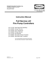
4.2.1.2 Home Tab without an ATS
Fig 1. HOME tab (idle)
Fig 2. HOME tab (pump running)

8
Operation
EPCT FIRE SERIES FIRE PUMP CONTROLLER MN124016EN August 2019 www.eaton.com
The HOME tab will display the incoming utility voltage
and frequency along with the state of the contactor(s)
and motor. The HOME tab will display the current system
pressure reading along with the programmed Start and
Stop setpoints. At the bottom of the HOME tab is the
Notification Area which shows all status, alarms, and timers
indications with visuals to show which signals are sounding
the audible alarm; the date, time, and operation mode are
display below the Notification Area.
When the controller receives a call-to-start signal and
successfully starts the pump motor, visual indication will
be provided by showing the “M” contact in a closed state,
a border around the Motor/Pump, and a motor spinning
graphic. There will be a Pump Running status in the
Notification Area
4.2.1.3. Home screen of a controller without an ATS (motor running)
Fig 3. HOME tab with ATS
The HOME tab will display the incoming voltage and
frequency for both sources along with the state of the
transfer switch breakers, Source 2 external disconnect
handle, and the motor. The HOME tab will display
the current system pressure reading along with the
programmed Start and Stop setpoints. At the bottom of the
HOME tab is the Notification Area which shows all status,
alarms, and timers indications with visuals to show which
signals are sounding the audible alarm; the date, time, and
operation mode are display below the Notification Area.
When the controller receives a call-to-start signal and start the
pump motor, visual indication will be provided by showing a
border around the Motor/Pump, and a motor spinning graphic.
There will be a Pump Running status in the Notification Area.
4.3 Automatic start / stop
The EPCT controller will automatically start and stop the fire
pump motor as dictated by the features supplied and their
programmed set-point values. A summary of the controller
intelligence and supervisory circuits that constantly monitor
the condition of the system pressure, inputs, and system
alarm points is provided.
4.3.1 Manual start sequence
Manual start is defined as a local start, remote manual start,
remote manual start/stop, or emergency start. Whenever
the motor is running via a manual start, the motor needs to
be manually stopped via the stop pushbutton located on the
enclosure flange.

9
Operation
EPCT FIRE SERIES FIRE PUMP CONTROLLER MN124016EN August 2019 www.eaton.com
4.3.2 Automatic start sequence
Automatic start is defined as a low-pressure condition,
deluge valve start or a remote auto start. Whenever the
motor is running via an automatic start, the motor can
automatically stop once all starting conditions have returned
to normal and the RPT has finished its timing cycle. If
the controller is programmed for manual stop, the motor
needs to be manually stopped via the local stop pushbutton
located on the enclosure flange.
4.4 Control inputs
The EPCT has ten (10) programmable inputs.
CAUTION
Severe damage could be caused to the microprocessor
boards if a voltage is applied to these inputs. They are
internally powered.
4.4.1 Control input descriptions
The Control Input state definitions are as follows.
Connected - When the input is shorted by an external
contact or connection.
Disconnected - When the input is NOT shorted by an
external contact or connection.
The Control Input operations are defined as follows.
ote:N Terminal 49 is common to all the inputs outlined below.
4.4.1.1. Remote manual start
When this input is in the “Connected” state, the controller
will initiate the manual start sequence. Remote start will
ignore the sequential start timer (SST) and the minimum
run timer (RPT) and will require a manual stop signal to shut
down the pump.
4.4.1.2. Remote manual stop
When this input is in the “Connected” state, the controller
will not permit starting of the pump with the exception of
Emergency Start and will shut down the pump, if already
running. Remotely stopping a full service fire pump
controller needs to be approved by the local authority.
4.4.1.3. Remote manual start/stop
When this input is in the “Connected” state, the controller
will initiate the manual start sequence. Remote start will
ignore the sequential start timer (SST) and the minimum
run timer (RPT) and will require a manual stop signal to shut
down the pump. When this input is in the “Disconnected”
state, the controller will shut down the pump, if already
running. Remotely stopping a full service fire pump
controller needs to be approved by the local authority.
4.4.1.4. Remote auto start
When this input is in the “Connected” state, the EPCT
controller will initiate an automatic start sequence. If
programmed to automatically shutoff the pump, when the
input is in a “Disconnected” state and the RPT has elapsed,
the controller will shut down the pump. This input is
typically wired to a separate pressure switch when the use
of a pressure transducer is not desired.
ote:N When the controller is programmed for foam
operation, the remote auto start input be a normally
closed input that will open to initiate a start.
4.4.1.5. Deluge valve start
When this input is in the “Disconnected” state, the EPCT
controller will initiate an automatic start sequence. If
programmed to automatically shutoff the pump, when the
input is in a “Connected” state and the RPT has elapsed,
the controller will shut down the pump. This input is
typically wired to remote water control equipment that
starts the controller before the pressure transducer does.
4.4.1.6. Low suction
When this input is in the “Connected” state, the EPCT
controller will signal a visual indication in the notification
area for Low Suction. If the controller is programmed
for Low Suction Shutdown it will initiate the shutdown
sequence. Refer to Section 5 to program Low Suction
Shutdown.
4.4.1.7. Low foam level
When this input is in the “Connected” state, the EPCT
controller will signal a visual indication in the notification
area for Low Foam Level. If the controller is programmed for
Low Foam Shutdown it will initiate the shutdown sequence.
Refer to Section 5 to program Low Suction Shutdown.
4.4.1.8. Proof pressure switch
When this input is in the “Connected” state, the EPCT
controller will signal a visual indication in the notification
area for Proof Pressure Switch. If Proof Pressure Switch
is enabled, the controller requires that this input is
“Connected” before allowing a start sequence. Refer to
Section 5 to program Proof Pressure Switch.
4.4.1.9. Low room temperature
When this input is in the “Connected” state, the EPCT
controller will signal a visual indication on the main display
board for Low Room Temperature. The Common Alarm relay
will also de-energize for remote monitoring of this alarm.
4.4.1.10. High room temperature
When this input is in the “Connected” state, the EPCT
controller will signal a visual indication on the main display
board for High Room Temperature. The Common Alarm relay
will also de-energize for remote monitoring of this alarm.

10
Operation
EPCT FIRE SERIES FIRE PUMP CONTROLLER MN124016EN August 2019 www.eaton.com
4.4.1.11. Interlock
When this input is in the “Connected” state, the EPCT
controller will not permit a start of the motor except for
Emergency Start. This input is typically used in backup style
systems. For example, the Engine Running contacts from
the backup Diesel Engine Controller are wired into this
input. When the Diesel Engine is running, it will lock out the
EPCT panel to prevent it from starting.
4.4.1.12. Low reservoir
When this input is in the “Connected” state, the EPCT
controller will signal a visual indication on the main display
board for Low Reservoir. The Common Alarm relay will also
de-energize for remote monitoring of this alarm.
4.4.1.13. High reservoir
When this input is in the “Connected” state, the EPCT
controller will signal a visual indication on the main display
board for High Reservoir. The Common Alarm relay will also
de-energize for remote monitoring of this alarm.
4.4.1.14. Go to source 1
When this input is in the “Connected” state, the EPCT
controller will transfer the transfer switch to Source 1, if it
is not already on Source 1, regardless of the state of the
incoming voltage. “Disconnecting” this input, the controller
will resume normal transfer switch operations.
4.4.1.15. Go To Source 2
When this input is in the “Connected” state, the EPCT
controller will transfer the transfer switch to Source 2, if it
is not already on Source 2, regardless of the state of the
incoming voltage. “Disconnecting” this input, the controller
will resume normal transfer switch operations.
4.4.1.16. Enable Sequential Start
When this input is in the “Connected” state and the timer
is programmed, the controller will delay all automatic
starting means for the duration of the programmed timer.
4.5 Output relays
The primary control outputs of the EPCT controller are dry
relay contacts. These relays are comprised of two separate
“Form C” outputs for Power/Phase Failure, Phase Reversal,
Common Alarm, and Pump Run. The alarm relays are UL/
CSA rated at 8A 250Vac / 30Vdc.
Each relay has a green LED on the I/O board to indicate the
relay status. If the LED is “On” the relay is energized and
“Off” the relay is de-energized.
4.5.1 Startup (1CR)
The Startup (1CR) relay is the motor start relay. It will
energize when there is a call-to-start. When the relay closes,
it provides full voltage to the start/run contactor. This is not
a reprogrammable relay.
4.5.2 Acceleration (2CR)
The Acceleration (2CR) relay is used on reduced voltage
starting controllers only. It will energize after the
programmed acceleration time delay expires. When the
relay closes, it provides full voltage to the run contactor(s).
This is not a reprogrammable relay.
4.5.3 Common alarm (3CR)
The Common Alarm (3CR) relay is a normally energized
relay and is used to alarm on various alarming conditions.
The relay will de-energize (change state) when any of the
events programmed into the Common Alarm Settings in the
Panel Setup tab becomes true.
4.5.4 Power / phase failure (4CR)
The Power/Phase Failure (4CR) relay is a normally energized
relay and is used to alarm when there is a voltage or phase
imbalance. The relay will de-energize when the voltage or
phasing levels exceed the allowable, programmed threshold.
4.5.5 Phase reversal (5CR)
The Phase Reversal (5CR) relay is used for remote
monitoring of a phase reversal condition. The phase reversal
alarm is factory set in an ABC configuration.
4.5.6 Pump run (6CR)
The Pump Run (6CR) relay is used for remote monitoring
when the pump is running. When the line current exceeds
20% of the programmed motor FLA, this relay will energize.

11
Programming
EPCT FIRE SERIES FIRE PUMP CONTROLLER MN124016EN August 2019 www.eaton.com
5.0 Programming
5.1 Introduction
The EPCT controller is fully programmable from the device’s
faceplate. Users can program set points as well as other
parameters. The time, date, and set points can only be
changed from the menu system.
The menu system is broken down to tab systems. These
include, Home, Startup, Panel Setup, Help, Pressure
Settings, Timer Values, ATS Settings (if equipped), Alarm
Setpoints, Inputs/Outputs, History/Statistics/Diagnostics,
and Optional Output Card(s) (if equipped).
5.2 Navigation
In order to navigate through the EPCT operating system,
press the tabs at the top of the screen to go through the
menu. If the main menu password is enabled, the user will
be prompted to enter the password to access any of the
tabs except for Help and History/Statistics/Diagnostics.
NOTICE
It is recommended to set up a main menu password to help
prevent any unauthorized access to the controller. This will
help prevent reprogramming the controller that will impede
the operation of the fire pump controller.
The controller does come with the ability to “Lockout” the
display after thirty (30) minutes of inactivity to minimize
accidental inputs. This feature will not inhibit the normal
operation of the controller. To unlock the display, the user
will be prompted to enter in “EPCT”.
In order to increase the longevity of the display board,
the controller will activate the screensaver after thirty (30)
minutes of inactivity. The screen saver will turn the screen
black and will show a moving EATON logo. To deactivate the
screensaver simply press anywhere on the screen.
All EPCT controller programmable features and associated
set-point possibilities are presented in Table 1.
Table 1
Description Range
Panel setup
Language English / French / Spanish / Portuguese / Turkish
/ Italian / Polish / Simplified Chinese / Dutch
Set time 24 Hours
Set date Any valid date
Set day of the week Any valid day of the week
Starting method Across the Line / Part Winding / Primary
Resistor / Autotransformer/ WYE-Delta Open /
Wye-Delta Close / Soft Start
Single phase start Enabled / Disabled
Auto shutdown Enabled / Disabled
Motor HP 0-9999 HP
Nominal voltage 200-7200V
Phases Single Phase / Three Phase
Description Range
System Frequency 50Hz / 60Hz
CT Ratio 50:0.1 / 100:0.1 / 150:0.1 / 300:0.1 / 500:0.1 /
800:0.1 / 1200:0.1
Motor FLA 1-999 A
Foam Controller Enabled / Disabled
Menu Password One (1) to seven (7) digit numeric / Disabled
Controller Serial Number Standard keyboard entry with space for fifty (50)
digits - Numeric and/or Alphabetical -
Pump Serial Number Standard keyboard entry with space for fifty (50)
digits - Numeric and/or Alphabetical
Screen Brightness 20%, 40%, 60%, 80%, 100%
Enable Welcome Screen Enabled / Disabled
Screen Lock Enable/Disable
Customer service contact
Enable Password Protection One (1) to seven (7) digit numeric / Disabled
Company Name Standard keyboard entry with space for fifty (50)
digits - Numeric and/or Alphabetical
Contact Name Standard keyboard entry with space for fifty (50)
digits - Numeric and/or Alphabetical
Phone Number Numeric entry with space for 15 digits
Email Standard keyboard entry with space for fifty (50)
digits - Numeric and/or Alphabetical
Service message trigger
Number of Hours Run 1-999 Hour
Number of Starts 1-999 Pump Runs
Specific Time and Date 24 Hours - Any valid date
De-energize Common Alarm Enabled / Disabled
Pressure settings
Start Pressure 0-999 PSI / Disabled
Stop Pressure 0-999 PSI / Disabled
Low Pressure Alarm 0-999 PSI / Disabled
High Pressure Alarm 0-999 PSI / Disabled
Start Above Pressure 0-999 PSI / Disabled
Pressure Variance Recording 1-999 PSI / Disabled
Hourly Pressure Recording Enabled / Disabled
Low suction shutdown
Enabled / Disabled
Shutdown Delay 0-99 Seconds / Disabled
Reset Mode Automatic / Manual
Automatic Reset Delay 0-99 Seconds / Disabled
Low foam shutdown
Enabled / Disabled
Shutdown Delay 0-99 Seconds / Disabled
Reset Mode Automatic / Manual
Automatic Reset Delay 0-99 Seconds / Disabled
Proof Pressure Switch Enabled / Disabled
Pressure Units PSI / BAR / kPa
Pressure Transducer Enabled / Disabled
Calibrate Pressure
Transducer
Calibrate Using 0 PSI / Calibrate Using Current
Pressure / Reset to Factory Default
Timer values
Minimum Run Time Four (4) digit numeric entry in Minutes:
Seconds / Disabled
Acceleration Timer 0-10 seconds / Disabled
Sequential Start Timer 0-999 seconds / Disabled
Fail to Start Timer 0-999 seconds / Disabled

12
Programming
EPCT FIRE SERIES FIRE PUMP CONTROLLER MN124016EN August 2019 www.eaton.com
Description Range
Fail to Stop Timer 0-999 seconds / Disabled
Weekly motor
test timer
Enabled / Disabled
Day of the Week Any valid day of the week
Time of Day 24 Hours
Test Interval 1-52 weeks
Run Time Four (4) digit numeric entry in Minutes:
Seconds / Disabled
Drain Valve Solenoid Enabled / Disabled
ATS settings (if equipped)
Time Delay S1 to S2 Three (3) digit numeric entry in Minutes:
Seconds / Disabled
Time Delay S2 to S1 Three (3) digit numeric entry in Minutes:
Seconds / Disabled
Time Delay Neutral Three (3) digit numeric entry in Minutes:
Seconds / Disabled
Time Delay Engine Start Three (3) digit numeric entry in Minutes:
Seconds / Disabled
Time Delay S2 Fail 0-9 seconds / Disabled
Time Delay Engine Cooldown Three (3) digit numeric entry in Minutes:
Seconds / Disabled
Dual utility
Enabled / Disabled
Preferred Source Source 1 / Source 2
Weekly engine
test timer
Enabled / Disabled
Day of the Week Monday / Tuesday / Wednesday / Thursday /
Friday / Saturday / Sunday
Time of Day 24 Hours
Test Interval 1-52 weeks
Run Time Four (4) digit numeric entry in Minutes:
Seconds / Disabled
Transfer Load Enabled / Disabled
Alarm setpoints
Phase Rotation ABC / CBA / Disabled
Phase Failure Alarm
Setpoint
0-100% / Disabled
Motor Overlead Setpoint 100-999%
Transducer Fail Pump Start Enabled / Disabled
Abort Motor Test on Low
Voltage
Enabled / Disabled
Voltage alarm settings
Source 1 Under Voltage 0-100% / Disabled (Dropout)
0-100% / Disabled (Pickup)
Source 1 Over Voltage 100-999% / Disabled (Dropout)
100-999% / Disabled (Pickup)
Source 2 Under Voltage 0-100% / Disabled (Dropout)
0-100% / Disabled (Pickup)
Source 2 Over Voltage 100-999% / Disabled (Dropout)
100-999% / Disabled (Pickup)
Frequency alarm settings
Source 1 Under Frequency 0-100% / Disabled (Dropout)
0-100% / Disabled (Pickup)
Source 1 Over Frequency 100-999% / Disabled (Dropout)
100-999% / Disabled (Pickup)
Source 2 Under Frequency 0-100% / Disabled (Dropout)
0-100% / Disabled (Pickup)
Description Range
Source 2 Over Frequency 100-999% / Disabled (Dropout)
100-999% / Disabled (Pickup)
Inputs/outputs
Input 1 See Table 2
Input 2 See Table 2
Input 3 See Table 2
Input 4 See Table 2
Input 5 See Table 2
Input 6 See Table 2
Input 7 See Table 2
Input 8 See Table 2
Input 9 See Table 2
Input 10 See Table 2
Input On Delay Timer 0-999 seconds / Disabled
Input Off Delay Timer 0-999 seconds / Disabled
Latch Until Reset Enabled / Disabled
Failsafe Enabled / Disabled
3CR Relay See Table 3
4CR Relay See Table 3
5CR Relay See Table 3
6CR Relay See Table 3
Pressure Above 0-999 PSI / Disabled
Pressure Below 0-999 PSI / Disabled
Load Shed Controller
Start Delay
0-10 seconds / Disabled
Relay On Delay Timer 0-999 seconds / Disabled
Relay Off Delay Timer 0-999 seconds / Disabled
Latch Until Reset Enabled / Disabled
Failsafe Enabled / Disabled
5.3 Startup tab
Refer to Appendix B for the menu structure of the Startup tab.
5.3.1 Quick setup
Quick Setup is a step-by-step process that allows the user
to program the time, day of the week, date, start pressure,
stop pressure, automatic shutdown, and minimum run time
(if automatic shutdown was enabled). If all settings are
correct, the user will press Accept to save the changes.
5.3.2 Setup phase reversal
Guides the user through a step-by-step process to verify
that the motor is or is not spinning in the correct direction.
Pressing “Motor Bump” will start a five (5) second
countdown timer and, once elapsed, will bump the motor for
a period of one (1) second. If spinning correctly, the controller
will save the phase reversal setpoint into the programming. If
the motor is not spinning correctly, the controller will provide
a prompt on the necessary changes required.
For controllers equipped with an ATS, the sequence will
continue. Pressing the “Start Generator/Transfer” will
initiate a call-to-start on the generator and, once voltage
is available on the Source 2 input, the ATS will transfer to

13
Programming
EPCT FIRE SERIES FIRE PUMP CONTROLLER MN124016EN August 2019 www.eaton.com
Source 2. Pressing “Motor Bump” will start a five (5) second
countdown timer and, once elapsed, will bump the motor for
a period of one (1) second. If spinning correctly, the controller
will save the phase reversal setpoint into the programming. If
the motor is not spinning correctly, the controller will provide
a prompt on the necessary changes required.
5.3.3 Flow test
Records the voltage, current, pressure, and flow (if
equipped) for a given flow rate. This information is stored in
the Startup file that can be downloaded onto a USB drive or
viewed through the History/Statistics/Diagnostics tab.
5.3.4 Manual/Automatic start
Records the number of times and the duration of each run,
both via Automatic and Manual means into the Startup file.
Manual Starts provides a Start and Stop button on screen
to initiate manual calls to start. The screen will show the
voltage, frequency, current, and pressure along with the
number of starts.
Automatic Starts provides a “Drop Pressure” button that will
energize the drain valve solenoid to drop pressure within the
sensing line. When the controller registers a low pressure
condition, the drain valve will close, and the controller will
initiate an automatic call-to-start. If activating the drain valve
solenoid is not ideal, the user can manually drop pressure
from the sensing line to achieve the same outcome.
If equipped with an ATS, means are provided on both
Manual and Automatic Start screens to start the generator
and transfer over to the secondary source without having to
drop out normal power.
5.3.5 Test alarm
Buttons are used to trigger specific output relays to verify
alarm connections and general operation of the relay. The
relay will stay latched until either the button is depressed
again or until the user leaves the screen.
5.3.6 USB download
Allows the user to save the statistics, diagnostics, message
history, startup, and configuration files to a USB device.
5.4 Panel setup tab
Refer to Appendix C for the menu structure of the Panel
Setup tab.
5.4.1 Language
Nine (9) languages are offered as standard: English, French,
Italian, Spanish, Portuguese, Chinese, Polish, Dutch, and
Turkish. Refer to Appendix B for programming.
5.4.2 Set time
Factory set to Mountain Standard Time (MST). This menu
item allows the user to adjust the time in a 24-hour format.
5.4.3 Set date
Factory set but allows the user to adjust if needed.
5.4.4 Set day of the week
Factory set but allows the user to adjust if needed.
5.4.5 Starting method
Used to differentiate what starting method the controller
what built to. Changing the starting method also adjusts
the acceleration timer. The acceleration timer can be further
adjusted in the Timer Values tab. These are the default
acceleration timer for each Starting Method:
Across the Line – Disabled
Part winding – 2 Seconds
Primary resistor – 2 Seconds
Autotransformer – 2 Seconds
Wye delta open – 2 Seconds
Wye delta closed – 2 Seconds
Soft start – 4 Seconds
5.4.6 Single phase start
Factory disabled. If disabled, the controller will not allow
starting if a single-phase condition is present; this will not
shut down the motor if it has registered a valid pump run
condition prior to the single-phase condition. If enabled, the
controller will attempt to start the motor if a single-phase
condition is present.
5.4.7 Auto shutdown
The automatic shutdown mode is user selectable; factory
disabled. If the automatic shutdown mode is disabled, the
pump motor must be stopped via the local stop pushbutton,
whether or not the motor started via an automatic start. If
the automatic shutdown mode is enabled, the controller will
stop the pump motor automatically after all starting causes
have been returned to normal (stop pressure has been
achieved) and the running period timer elapsed.
5.4.8 Controller HP
Factory set. Used to set motor HP.
5.4.9 Nominal voltage
Factory set. Used to set the nominal system voltage. This
value will also be used to determine any under voltage or
overvoltage conditions, as well as phase loss conditions.
/