Page is loading ...


PS-7 Power Supply

NOTE:
Care should be taken to insure
that adequate clearance is provided
around the PS-7 for proper circula-
tion of air, especially around the heat
sinks. Also, avoid placing books, pa-
pers, or other pieces of-equipment on
top of the unit as overheating could
result.
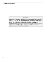
Fig. I-Rear Panel Controls and Connections
7-25-79
2

PS-7 POWER SUPPLY, MODEL 1502
General Description
The PS-7 is a
13.6
volt, DC regulated power supply capable of de-
livering up to 25 amps of continuous current. Excellent voltage
regulation is provided by a silicon monolithic integrated circuit
and associated circuitry. Output voltage and current are adjust-
able with internal controls which have been factory set to provide
13.6 volts at up to
25
amps. Other features include short circuit
and overvoltage protection and programmable primary voltages.
An auxiliary 13.6
VDC
output is provided on the rear panel and
is fused internally at I amp. Primary voltages of 100, 120, 200,
and 240 VAC, 50-60 Hz may be used with the
PS-7
and may be
quickly changed via the programming switches. For demanding
duty cycles, such as extended RTTY or SSTV transmission, the
model 1529 FA-7 Cooling Fan is recommended for additional
cooling, especially at ambient, temperatures above 25°C.
Current Overload Protection
When the
PS-7
is subjected to a current overload or short circuit
condition, the regulator circuit will automatically shut down. The
unit may be reset by momentarily switching the ON-OFF switch
on the TR-7 to OFF or by removing the AC primary voltage to the
PS-7. The power transformer is protected by an 8 ampere type
ABC
fuse on primary voltages of 100 or 120 VAC or a 4 ampere
type
M
TH
fuse on 200 or 240 VAC. Refer to Figure 1 for location
on the rear panel.
This
fuse
should he
rcplaced
with another fuse
of
the
same type and
ratin
g.
The auxiliary DC output is intern-
ally fused with a 1 amp type MDL fuse. This is located inside the
unit, on
the
regulator P.C. board. This fuse should be
replaced
only
with
another fuse of the same type and rating.
10-8-79
3

Overvoltage Protection
If the PS-7 regulator section should fail or one of the pass tran-
sistors should short, the unit will automatically shut down. If the
DC output voltage should soar above 16 VDC, an SCR crowbar
clamps the output to ground to protect the load and open the pri-
mary fuse. This fuse should
be
replaced with another of the same
type
and rating after determining
the
cause of the
overload.
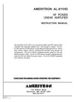
Line Voltage Programming
The
PS-7
comes factory set for 120 VAC 50-60 Hz operation. To
change the primary input range, simply remove the four screws
holding the programming plate. Refer to Figure 2. As an example,
suppose the line voltage measured 200 VAC. Remove the plate
and slide the voltage switch to
200/240.
Then slide the HI/LO
switch to LO. Rotate the plate until 200 shows up in the window
and the LO switch fits through its locator hole. Reinstall the four
screws. If 200 or 240 VAC operation is desired, he
sure
to replace
the fuse with a 4
amperc
type
M
TH fuse.
100
120
120vac
+-lO%
50-60 Hz
Hi
Lo
200
240
Range:108-132vac
Ia
Hi
Lo
1OOvac
+-lO%
50-60 Hz
Range:90-110vac
I
100 120
240vac
+-l0%
50-60 Hz
Hi Lo 200
P
240
Range:216-264vac
IM
100 120
200vac
+-lO%
50-60Hz
Hi Lo 200
cl
240
Range:180-220vac
Fig. 2-PS-7 Line Voltage Programming
10-8-79
4

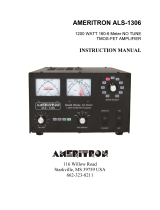
Linear Amplifier
All necessary connections for use with a linear amplifier are
provided on the rear panel of the PS-7. Refer to Figure 3.
Connect a patch cord to the ALC Jack and the VOX Jack.
Factory Service
The PS-7 will be checked and serviced at the factory for a
nominal fee if there is no evidence of tampering. Transporta-
tion charges are extra. Any necessary repairs will be made on a
time and material basis. Please write or call the factory for
authorization before returning the unit for service. Requests
for authorization should be addressed to:
R.L. DRAKE COMPANY
540 Richard Street
Miamisburg, OH 45342
Attn: Customer Service Dept.
Telephone: (Area Code 513) 866-3211
Telex No. 288-017
10-17-79

Fig.
3-Interconnection
of
PS-7
and Linear Amplifier
Linear Amplifier
CONTROL
CAB
I
RV7
CONTROL
CABLE
I
I
I
GROUND
STRAP
--
-----1-
+
I
-t
I,

AC INPUT:
PS-7 POWER SUPPLY
SPECIFICATIONS
100, 120, 200, or 240 Volts AC,
+-
10% 50-60 HZ.
DC OUTPUT:
13.6 Volts DC with less than 3mV RMS
of ripple at 25 amperes load.
*
DC CURRENT:
25 amperes continuous.( at 25°C. ambient )
DC AUX VOLTS:
13.6
VDC regulated.
DC AUX CURRENT: 1
ampere maximum.
CONNECTORS:
Aux DC Phono Jack
ALC Phono Jack
VOX Contact Phono Jack
Fan AC
Ground Connection
DIMENSIONS:
Width-13-3/4”
(34.93 cm.)
Height-5-1/4”
(13.34 cm.)
Depth-12-1/2”
(31.75 cm.)
WEIGHT:
32-1/4 lbs. (15 kg)
*25
amperes continuous
@
up to 40°C ambient with optional
FA-7 FAN (Model 1529)
3-20-80
7

NOTES
3-20-80
/