Eaton Eaton series Instructions Manual

Category
Uninterruptible power supplies (UPSs)
Type
Instructions Manual

This manual is also suitable for

Revision 01
Battery Upgrade Instructions
For use with the Eaton
®
9355 (20–30 kVA)
Eaton Series
Eaton reserves the right to change specifications without prior notice. Eaton is a registered trademark of Eaton. All other trademarks are
property of their respective companies.
©Copyright 2018 Eaton, Raleigh, NC, USA. All rights reserved. No part of this document may be reproduced in any way without the
express written approval of Eaton.
IMPORTANT SAFETY INSTRUCTIONS SAVE THESE INSTRUCTIONS
This manual contains important instructions that you should follow during installation and maintenance
of the UPS and batteries. Please read all instructions before operating the equipment and save this
manual for future reference.
CONSIGNES DE SÉCURITÉ IMPORTANTES CONSERVER CES INSTRUCTIONS
Ce manuel comporte des instructions importantes que vous êtes invité à suivre lors de toute
procédure d'installation et de maintenance de la PDU. Veuillez consulter entièrement ces instructions
avant de faire fonctionner l'équipement et conserver ce manuel afin de pouvoir vous y reporter
ultérieurement.
Battery Upgrade Instructions for 9355 (20–30 kVA) —Rev 01 iii
TTaabbllee ooff CCoonntteennttss
11 IInnttrroodduuccttiioonn....................................................................................................................................................................................................................................................................................................11
22 BBaatttteerryy UUppggrraaddee PPrroocceedduurree........................................................................................................................................................................................................................................................33
2.1 Complete UPS Battery Upgrade Procedure ...................................................................................................... 9
iv Battery Upgrade Instructions for 9355 (20–30 kVA) —Rev 01
Table of Contents
Battery Upgrade Instructions for 9355 (20–30 kVA) —Rev 01 1
CChhaapptteerr 11 IInnttrroodduuccttiioonn
The two-row battery tray (P/N: P-103000933, revision 5) that was used for the 9355 20-30kVA is now
discontinued. Upgrade kit P-106000220 facilitates replacing one existing two-row battery tray assembly with
two single-row battery assemblies (with two-circuit connectors). Along with an adapter harness, it is
permanently installed in the UPS to convert from single-circuit battery tray connections to the two-circuit
connectors to mate with the pair of new single-row assemblies.
Figure 1. Discontinued Two-Row Battery Tray P-103000933
Figure 2. Upgrade Kit P-106000220 (Two Cartons) Includes Two Single-Row Battery Trays and Wiring
Harness Adapter
2 Battery Upgrade Instructions for 9355 (20–30 kVA) —Rev 01
Figure 3. Wiring Harness Adapter P-152001881
The total battery string voltage in a 9355 20-30 kVA UPS is 216V (18 batteries, where is each battery is 12V
nominal). The single-tray configuration that is being replaced holds 18 batteries. Two strings fit in each battery
shelf of the 9355 20-30 kVA UPS. The single-tray red connector is the most positive connection while the black
is the negative connection. The white connector presents the middle point in the single-tray configuration,
where 108V is measured from the white to the red and 108V from the white to the black. The white connector
is used for CSE testing only.
The replacement tray sets contain nine batteries each, such that it takes two trays to complete one string.
Each P-106000220 kit includes two single-row battery trays and two harness adapters. Only one harness
adapter is needed for the installation; the second harness adapter is a spare.
Introduction
Battery Upgrade Instructions for 9355 (20–30 kVA) —Rev 01 3
CChhaapptteerr 22 BBaatttteerryy UUppggrraaddee PPrroocceedduurree
WARNING
This procedure involves interacting with components that may be energized.
Any and all work can involve hazards when working on electrical equipment. The work must be done in
accordance with all applicable local, federal, or other safety requirements and must be performed by qualified
personnel.
1. Remove the 9355 20–30kVA front door (see Figure 4).
Figure 4. Remove the UPS Front Door
!
IMPORTANT
In the event of input power failure while performing this procedure, battery backup will not be available.
2. Follow the instructions in the manual to place the 9355 20-30kVA UPS in bypass and in maintenance
bypass. However, if the UPS cannot be placed in maintenance bypass, this procedure can still be
performed.
3. Open the UPS battery circuit breaker CB2 (see Figure 5). Follow lockout/tagout procedures.
4. Remove the thirteen M5 bolts from the battery panel cover (dead front) and remove it (see Figure 5).
4 Battery Upgrade Instructions for 9355 (20–30 kVA) —Rev 01
Figure 5. Open the Battery Circuit Breaker CB2 and Remove the Battery Dead Front
5. As shown in Figure 6, disconnect the positive (red) and negative (black) battery connectors for all the
battery trays.
NOTE If an external battery cabinet is attached, it must also be disconnected from the UPS.
Figure 6. Disconnect All Battery Trays
Battery Upgrade Procedure
Battery Upgrade Instructions for 9355 (20–30 kVA) —Rev 01 5
WARNING
All battery trays must be disconnected before proceeding.
6. Remove the two M5 bolts that secure the retaining bracket on the battery shelf for the battery tray to be
replaced (see Figure 7).
Figure 7. Remove the Battery Retaining Bracket
7. Remove the existing two-row battery tray from the unit (see Figure 8).
Battery Upgrade Procedure
6 Battery Upgrade Instructions for 9355 (20–30 kVA) —Rev 01
Figure 8. Remove the Old Two-Row Battery Tray
8. Slide two new single-row trays in place of the tray that was removed. The two new single-row trays are
now side-by-side with one old dual-row tray on the same shelf, forming two battery strings (see Figure 9).
Figure 9. Slide Two Single-Row Battery Trays into Place
9. Re-install the battery retaining bracket and secure using the two M5 bolts removed in Step 6(see
Figure 10).
10. Cut the tie wrap securing the UPS battery harness to the battery retaining bracket (see Figure 10).
Battery Upgrade Procedure
Battery Upgrade Instructions for 9355 (20–30 kVA) —Rev 01 7
Figure 10. Re-install Battery Retaining Bracket and Remove Tie-Wraps
11. Install the adapter on the UPS side battery harness (see Figure 11). Connect the adapter to the UPS battery
harness (red–to–red and black–to–black).
WARNING
It is critical that these connections are correct. A harmful arc flash will occur if these connections are crossed.
Figure 11. Install Battery Harness Adapter
12. Slide a heat shrink tubing and center it over the connectors. Use tie-wraps at each end of the heat shrink
tubing to hold it in place (see Figure 12).
Battery Upgrade Procedure
8 Battery Upgrade Instructions for 9355 (20–30 kVA) —Rev 01
Figure 12. Install Heat Shrink Tubing and Secure Using Tie-Wraps
13. Anchor the UPS battery harness to the battery retaining bracket using tie wraps (see Figure 13).
Figure 13. Anchor Battery Harness to Battery Retaining Bracket
CAUTION
Observe proper precautions when verifying polarity. It is recommended that polarity checks are performed by
qualified personnel knowledgeable of batteries.
14. Verify the correct polarity before making connections.
15. Connect the UPS battery harness to the two newly installed single-row battery trays (see Figure 14).
Battery Upgrade Procedure
Battery Upgrade Instructions for 9355 (20–30 kVA) —Rev 01 9
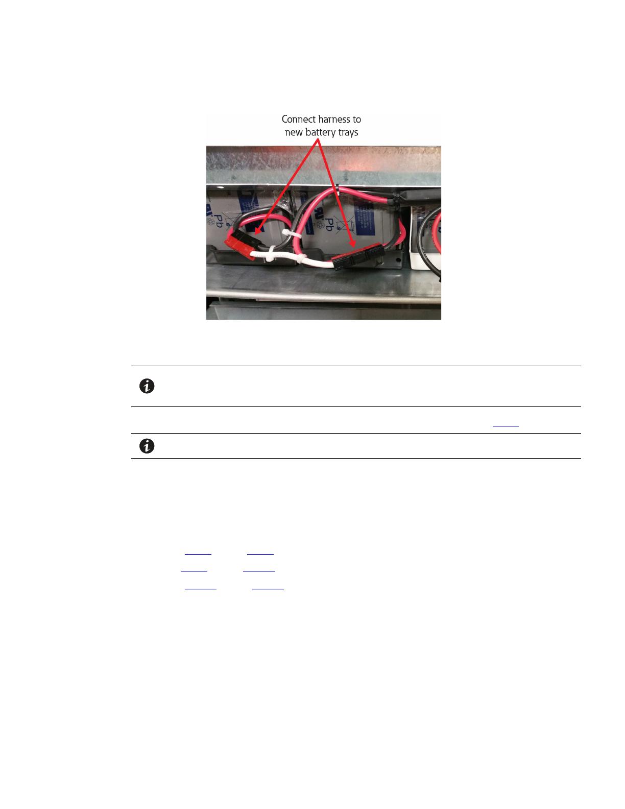
Figure 14. Connect Battery Harness to New Battery Trays
16. Connect the UPS battery harness to the existing battery trays. Verify polarity before making each
connection. All cabinet strings should now measure 216V (nominal)
NOTE When making connections, it is preferable to make all connections of the same color
first, then make all connections of the other color. For example, make all red
connections first, then make all black connections.
17. Re-install the battery cover panel (dead front) using the thirteen M5 bolts removed in Step 4.
NOTE If an external battery cabinet is attached, reconnect it to the UPS.
18. Follow the instructions in the manual to command the unit to normal mode of operation.
19. Reinstall the unit front door.
22..11 CCoommpplleettee UUPPSS BBaatttteerryy UUppggrraaddee PPrroocceedduurree
If replacing all batteries in the unit:
1. Perform Step 1 through Step 5 of the upgrade procedure
2. Repeat Step 6 through Step 14 for each battery tray
3. Perform Step 15 through Step 19
Battery Upgrade Procedure
01
01
  • Page 1 1
  • Page 2 2
  • Page 3 3
  • Page 4 4
  • Page 5 5
  • Page 6 6
  • Page 7 7
  • Page 8 8
  • Page 9 9
  • Page 10 10
  • Page 11 11
  • Page 12 12
  • Page 13 13
  • Page 14 14

Eaton Eaton series Instructions Manual

Category
Uninterruptible power supplies (UPSs)
Type
Instructions Manual
This manual is also suitable for

Ask a question and I''ll find the answer in the document

Finding information in a document is now easier with AI