Page is loading ...

Publication: AMEN00027 2017-11-06
BARRIER®GLIDER
COLD STORAGE DOOR
MODEL 7100
This manual covers units ordered 11-6-2017 to date
for Encoder, i-Comm, GUI change.
For doors ordered prior to 11-6-2017 refer to 7100N.
Installation/Owner’s Manual
Language: English (Hazards are in English and French)
The English version of this manual shall prevail over any
error in, or conflicting interpretation of, any translations.

2Publication: AMEN00027 2017-11-06
BARRIER®GLIDER Model 7100 Installation/Owner’s Manual Rite-Hite®
TABLE OF CONTENTS
Fork and scissors lift
Hydro level
10ft [3M] Step ladder
Cordless drill
25ft [8M] Tape measure
Wire strippers
6ft [2M] Carpenters level
Utility knife
(2) 15/16in [24mm] open end wrenches
Hammer
1/2in [13mm] Masonry and/or drill bit for thru bolting
7/16in [11], 1/2in [13], 9/16in [14] open end and/or socket
wrench
11/16in x 12in [17mm x 305mm] drill bit for thru bolting
Straight screwdriver (small 1/8in [3mm] spade)
Hardware for mounting the header, support posts,
retention rod, blower and perimeter seals to wall are
provided. Caulk for perimeter seals is not provided.
Retention Cord/Spring 53700460 (3)
Kit, 7100, Encoder 53701004 (1)
Panel Blower/Heater 53700647 (1)
Kit, Controller i-COMM 3 53701043 (1)
Fuse, 1 Amp 51000002 (2)
Fuse, 3.5 Amp 51000008 (2)
Fuse, 10 Amp 51000033 (3)
Fuse, 6 Amp 51000055 (2)
Fuse, 9 Amp 51000064 (2)
GUI 55150353 (1)
DOOR JAMB . . . . . . . . . . . . . . . . . . . . . . . . . . . . . . . . . . . . . .5
POLY LUMBER . . . . . . . . . . . . . . . . . . . . . . . . . . . . . . . . . . . .6
HEADER INSTALLATION . . . . . . . . . . . . . . . . . . . . . . . . . . . .8
THERMAL AIR SEAL INSTALLATION . . . . . . . . . . . . . . . . .11
PANEL INSTALLATION . . . . . . . . . . . . . . . . . . . . . . . . . . . . .15
RETENTION SYSTEM INSTALLATION . . . . . . . . . . . . . . . .17
ENCODER INSTALLATION . . . . . . . . . . . . . . . . . . . . . . . . . .18
ELECTRICAL INSTALLATION . . . . . . . . . . . . . . . . . . . . . . .20
i-COMM 3 INPUT / OUTPUT TABLE . . . . . . . . . . . . . . . . . .23
MAINTENANCE . . . . . . . . . . . . . . . . . . . . . . . . . . . . . . . . . . .28
FINAL CHECKLIST . . . . . . . . . . . . . . . . . . . . . . . . . . . . . . . .29
TROUBLESHOOTING . . . . . . . . . . . . . . . . . . . . . . . . . . . . . .30
WIRING DIAGRAMS . . . . . . . . . . . . . . . . . . . . . . . . . . . . . . .31
EXPLODED VIEWS WITH PARTS LIST . . . . . . . . . . . . . . . .40
ARCHITECTURAL DRAWING . . . . . . . . . . . . . . . . . . . . . . . .50
WARRANTY . . . . . . . . . . . . . . . . . . . . . . . . . . . . . . . .last page
SPECIAL FEATURES
i-COMM™ Universal Controller•
GUI™ controls (reduces need to open control box)•
Frequency drive (VFD) controls speed•
Fast smooth opening, maximum speed of 80 in/sec.•
Motor voltage 3 phase options: 60 Hertz: 208, 230,•
400V (50 Hz), 460, 575
Energy efficient high R-value flexible panels•
Thermal air sealing system•
Impactable panel retention system•
Heavy-duty industrial materials•
NOTICE TO END USER
Our mission is to “Improve Industrial Safety, Security
and Productivity Worldwide Through Quality and
Innovation.”
Thank you for purchasing the BARRIER®GLIDER door
from RITE-HITE DOORS, INC. The BARRIER®GLIDER
door is designed to be a fast, smooth opening, low
maintenance door that provides superior environmental
separation while reducing passage time and temperature
loss
The information contained in this manual will allow you to
operate and maintain the door in a manner which will
insure maximum life and trouble free operation.
This manual should be thoroughly read and understood
before beginning the installation, operation or servicing of
this door.
Complete Final Checklist prior to leaving site
When ordering parts through Aftermarket or Warranty
department, always include your door serial or RHC# to
be sure that you receive the correct parts. The RHC and
serial # for your door is located on a label on the side of
the control box, Figure 21. The actual parts used on your
door may be different than shown in this manual due to
special engineering or product improvement.
Your local RITE-HITE DOORS, INC. Representative
provides a Planned Maintenance Program (P.M.P.) which
can be fitted to your specific operation. Call your local
representative or RITE-HITE DOORS, INC. at 1-414-355-
2600 or toll free at 1-800-456-0600. If any procedures for
the installation, operation or maintenance of the
TRAKLINE have been left out of this manual or are not
complete, contact RITE-HITE DOORS, INC. Technical
Support at 1-563-589-2722.
INSTALLATION TOOLS REQUIRED RECOMMENDED PARTS

LOCKOUT/TAGOUT PROCEDURES
The Occupational Safety and Health Administration
requires that, in addition to posting safety warnings and
barricading the work area, the power supply has been
locked in the OFF position or disconnected. It is
mandatory that an approved lockout device is utilized. An
example of a lockout device is illustrated. The proper
lockout procedure requires that the person responsible
for the repairs is the only person who has the ability to
remove the lockout device.
In addition to the lockout device, it is also a requirement
to tag the power control in a manner that will clearly note
that repairs are under way and state who is responsible
for the lockout condition. Tagout devices have to be
constructed and printed so that exposure to weather
conditions or wet and damp locations will not cause the
tag to deteriorate or become unreadable.
RITE-HITE Corporation does not recommend any
particular lockout device, but recommends the utilization
of an OSHA approved device
(refer to OSHA regulation
1910.147). RITE-HITE
Corporation also recommends
the review and implementation
of an entire safety program for
the Control of Hazardous
Energy (Lockout/Tagout). These
regulations are available
through OSHA publication 3120.
SAFETY IDENTIFICATION
NOTE:
A Note is used to inform you of important installation,
operation or maintenance information.
Publication: AMEN00027 2017-11-06 3
Rite-Hite® BARRIER®GLIDER Model 7100 Installation/Owner’s Manual
SAFETY WARNINGS
Danger indicates the presence of a hazard that will
cause severe personal injury, death.
DANGER
!
Warning indicates the presence of a hazard that can
cause severe personal injury, death.
WARNING
!
Caution indicates the presence of a hazard that will or
can cause minor personal injury, death.
CAUTION
!
Notice communicates installation, operation, or
maintenance information that is safety related but not
hazard related and may cause equipment or property
damage.
NOTICE
GENERAL SAFETY NOTICES
When working with electrical or electronic controls, make sure
that the power source has been locked out and tagged according
to OSHA regulations and approved local electrical codes.
DANGER
!
Damage or debris may fall into electrical components causing
failure or severe equipment damage, when drilling holes in the
box.
DO NOT turn control box upside down or go too deeply into the
box.
NOTICE
Make sure to barricade the door opening on both sides to prevent
unauthorized use until the door has been completely installed.
WARNING
!
In freezer and cooler applications where a conduit passes from a
warm to cold temperature zone, the conduit must be plugged with
epoxy. This will help prevent condensation from forming in the
conduit. For more information, see Section 300-7a of the National
Electric Code.
NOTICE
Do not drill holes on top of control box to run conduit, as dust
particles and moisture may cause damage to electrical
components. The safest location is at the bottom. Failure to do so
will void warranty.
NOTICE
A qualified electrician should install the wiring in accordance with
local and national electrical codes.
Use lockout and tagout procedures to avoid injury.
DANGER
!
To reduce risk of injury or death, an earth ground connection
MUST BE made to the green/yellow control box ground
terminal. If metal conduit is used as the ground connector, an
N.E.C. approved ground bushing and green/yellow wire MUST
BE properly attached to the conduit for connection to the
ground terminal.
DANGER
!

4Publication: AMEN00027 2017-11-06
PRELIMINARY INSTALLATION CHECKS
BARRIER®GLIDER Model 7100 Installation/Owner’s Manual Rite-Hite®
NOTE:
Check for electrical prints included in the parts or
control box. They supersede any prints in this
manual.
Refer to GUI / i-COMM 3 Touch Screen Control
manual for installation.
Refer to Optional LED Countdown drawings for
installation.
Refer to Optional LED Preannounce drawings for
installation.
1. Alternate measurements in brackets are in [metric].
2. Match control box serial number with track serial
number.
3. Make sure you are working at the correct location
and have any required work permits.
4. Inspect installation site to make sure area is free of
overhead obstructions (sprinkler pipes, HVAC
systems, electrical supply lines, etc.) that might
interfere with the lifting of the header assembly
during installation.
5. Detour material handling equipment (fork lift trucks,
etc.) during the installation of the door.
6. Make sure that the electrician is ready to bring the
correct electrical power supply to the door control
box.
7. Make sure that the electrical power can be shut off
without interfering with other plant operations.
8. Move the entire crate of the door components as
close to the door opening as possible.
9. When removing the panels from the crates. Be sure
not to lean panels such that they crease.
10. If multiple doors are being installed, it is imperative
to install the proper control box with the matching
door unit. The serial # for your door is on a label
located on the side of the control box and lower
track, page 22.
11. Remove header from the crate by removing the
front and motor side of the crate, sliding the motor
off the edge of the crate and standing up. There will
be a block under the C-Channel to keep the motor
off the floor. This will allow a fork lift to pick up the
header using the header lifting tubes.
10. Remove plastic rivets and keep in a warm place.
11. To verify proper installation, use "Final Checklist" on
page 29.
12. Install Activation & Optional equipment after
verifying door operation.

Publication: AMEN00027 2017-11-06 5
DOOR JAMB
Rite-Hite® BARRIER®GLIDER Model 7100 Installation/Owner’s Manual
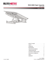
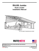
DOOR JAMB
1. Measure door opening width at the top (A) and floor
(B).
2. Measure door opening height at left side (C) and
right side (D).
3. Dimensions from steps 1-2 should be ± 1/2in
[13mm] of the dimensions listed on the serial
number label. If the measurements do not agree,
STOP! Contact your Rite‑Hite representative.
4. Surface MUST be flat, smooth and true with
opposite side (E).
5. Using a 6ft [2M] carpenter's level (F), verify that the
door jambs and header are plumb and
perpendicular.
6. Using a laser level (G), place a mark where the
laser is sighted on each side of the jamb to
determine if the floor is level. Measure both sides
from floor to the mark. If floor is not level to ± 1/8in
[3mm], shim under the lower track that (H) that is
the larger measurement.
7. For space clearance requirements, refer to
Architectural Drawings, Pages 50 - 54, or call your
Rite‑Hite Representative.
8. Measure between the jamb at the top of the opening
and at the floor and divide this measurement in half
and mark the centerline on the wall and on the floor.
Drop a plumb bob from the mark at the top of the
jamb and place a mark on the floor. The dimension
should be within 1/8in [3mm], if not place a mark
half way between these two marks.
A
B
D
C
E
F
G
H
Figure 1
It is HIGHLY recommended to thru-bolt the header
with the all threaded rods provided as this is the main
support for the door.
NOTICE

6Publication: AMEN00027 2017-11-06
POLY LUMBER
BARRIER®GLIDER Model 7100 Installation/Owner’s Manual Rite-Hite®
POLY LUMBER
1. Place vertical and horizonal poly Lumber pieces per
drawing specifications on Page 7.
2. Caulk behind poly lumber that surrounds the
opening.
3. Place header poly lumber tab behind pre-drilled
mounting hole.
4. Install support post poly lumber tab behind pre-
drilled mounting hole after header is in place.

Publication: AMEN00027 2017-11-06 7
Rite-Hite® BARRIER®GLIDER Model 7100 Installation/Owner’s Manual
POLY LUMBER

1. Find the center of the top of the jamb and mark an 8in [203mm] vertical line (A).
2. Place header (B) in front of the opening, by locating the factory assembled header lifting tubes (C) bolted to the
bottom of the header.
3. Make sure to clamp lifting tubes to fork lift and remove after complete.
4. Line up the center splicing bracket (D) on the header with the line on the center of the jamb.
5. Lift the header using a fork lift and bolt (H) the support posts to the header and place against the wall with the
bottom of the C-channel 7 1/2in [191mm] above the jamb.
6. If support posts do not rest on the floor with the header at 7 1/2in [191mm] (G) above the opening, check the
floor for obstructions and make corrections. Header should be level to ± 1in [25mm].
7. Thru-bolt the header to the wall at the (4) top (E) and (2) bottom mounting angles using the 6in Ø [152mm]
backer plates, all thread and nuts are provided. If wall is not solid, sleeves (not provided) must be used to
prevent wall from crushing and sagging of the header.
8. Plumb and fasten the support posts (F) to the wall in the (4 or 6 based on O.D.H) locations provided with the 6in
Ø [152mm] backer plates, all thread and nuts are provided.
9. Find the center bracket (D) of the header C-Channel. Chain should be tensioned so there is 1/8in [3mm] between
the bottom of the chain and the nylon wear pad.
8Publication: AMEN00027 2017-11-06
BARRIER®GLIDER Model 7100 Installation/Owner’s Manual Rite-Hite®
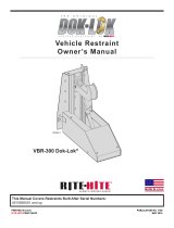
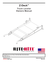
BI-PARTING HEADER INSTALLATION
C
L
A
F
E
D
B
C
G
Figure 2
H

1. Place header (B) in front of the opening, by locating the factory assembled header lifting tubes (C) bolted to the
bottom of the header.
2. Make sure to clamp lifting tubes to fork lift and remove after complete.
3. Place shorter jamb side support post (D) 9in [229mm] (H) past the edge of the jamb to the outside of the post.
4. Lift the header using a fork lift and bolt (I) the support posts to the header and place against the wall with the
bottom of the C-channel 7 1/2in [191mm] above the jamb.
5. If support posts do not rest on the floor with the header at 7 1/2in [191mm] (G) above the opening, check the
floor for obstructions and make corrections. Header should be level to ± 1in [25mm].
6. Thru-bolt the header to the wall at the (4) top (E) and (2) bottom mounting angles using the 6in Ø [152mm]
backer plates, all thread and nuts are provided. If wall is not solid, sleeves (not provided) must be used to
prevent wall from crushing and sagging of the header.
7. Plumb and fasten the support posts (F) to the wall in the (4 or 6 based on O.D.H) locations provided with the 6in
Ø [152mm] backer plates, all thread and nuts are provided.
8. Chain should be tensioned so there is 1/8in [3mm] between the bottom of the chain and the nylon wear pad.
Publication: AMEN00027 2017-11-06 9
Rite-Hite® BARRIER®GLIDER Model 7100 Installation/Owner’s Manual
SINGLE SLIDE NON-DRIVE STORAGE HEADER INSTALLATION
C
L
F
C
E
B
D
G
H
Figure 3
I

10 Publication: AMEN00027 2017-11-06
BARRIER®GLIDER Model 7100 Installation/Owner’s Manual Rite-Hite®
SINGLE SLIDE DRIVE STORAGE HEADER INSTALLATION
C
L
1. Place header (B) in front of the opening, by locating the factory assembled header lifting tubes (C) bolted to the
bottom of the header.
2. Make sure to clamp lifting tubes to fork lift and remove after complete.
3. Place shorter jamb side support post (D) 9in [229mm] past the edge of the jamb to the outside of the post.
4. Lift the header using a fork lift and bolt (I) the support posts to the header and place against the wall with the
bottom of the C-channel 7 1/2in [191mm] above the jamb.
5. If support posts do not rest on the floor with the header at 7 1/2in [191mm] above the opening, check the floor for
obstructions and make corrections. Header should be level to ± 1in [25mm].
6. Thru-bolt the header to the wall at the (4) top (E) and (2) bottom mounting angles using the 6in Ø [152mm]
backer plates, all thread and nuts are provided. If wall is not solid, sleeves (not provided) must be used to
prevent wall from crushing and sagging of the header.
7. Plumb and fasten the support posts (F) to the wall in the (4 or 6 based on O.D.H) locations provided with the 6in
Ø [152mm] backer plates, all thread and nuts are provided.
8. Chain should be tensioned so there is 1/8in [3mm] between the bottom of the chain and the nylon wear pad.
F
E
D
B
C
G
H
Figure 4
I

1. Find the center of the opening and place a mark on
the floor. From the center of the opening measure
and snap a chalk line on the wall the full height of
the opening 1/2 O.D.W. plus 5 1/2in [140mm] (J).
2. From the floor, measure O.D.H. plus 5 1/2in
[140mm] (K) to the top of the opening and snap a
chalk line the full width of the opening.
3. Position Thermal Air®sealing system (A) in front of
the opening with the extended section on the drive
side. Vertical extension (B) is fastened to the blower
on the drive side.
4. Fasten the aluminum seal retainer (C) Figure 7 to
the wall at the bottom Figure 8, and then every 18in
[457mm] using the #14 x 1 1/4in [32mm] hex head
screws provided if possible. Pull seal tight and place
a fastener thru the retainer and the white rope at the
top. Repeat for opposite side.
5. Pull top retainer to the previously marked line and
fasten to the wall.
6. Air seal must be twist and wrinkle free (F).
7. Air exhaust hole must not be obstructed (E) on both
sides.
8. After seal installation caulk the entire inside
perimeter of the aluminum retainer. Failure to do
this may result in frost or ice buildup.
9. Mount the blower (G) to the wall such that no part of
the blower sticks past the header and the vertical
section of the air seal will attach to it. The fabric
should be taught but not stretched when clamping
(H) to the blower. Use (4) #14 x 1 1/4in [32mm] hex
head screws provided.
NOTE:
Make sure aluminum retainers are to the outside of
the air seal.
Periodic cleaning of the perimeter air seal sealing
system may be required.
As of 2/1/2015:
Doors that are greater than 16ft-0in O.D.H. require
dual perimeter air seals. However dual air seals can
be ordered optional for any size door.
Publication: AMEN00027 2017-11-06 11
Rite-Hite® BARRIER®GLIDER Model 7100 Installation/Owner’s Manual
PERIMETER SEAL BP SINGLE BLOWER
D.O.W.
L
C
F
B
Figure 5
A
J
J
K
D,E

12 Publication: AMEN00027 2017-11-06
BARRIER®GLIDER Model 7100 Installation/Owner’s Manual Rite-Hite®
PERIMETER SEAL BP DUAL BLOWER
D.O.W.
L
C
F
B
Figure 6
Figure 7
C
A
5 1/2in
[140mm]
H
G
E
D
Figure 9
Figure 8
K
J
J

1. Find the center of the opening and place a mark on
the floor. From the center of the opening measure
and snap a chalk line on the wall the full height of
the opening:
(H) Drive Side: 1/2 O.D.W. plus 1/4in [6mm] and
(J) Storage Side: 1/2 O.D.W. plus 5 1/2in [140mm].
2. From the floor, measure O.D.H. plus 5 1/2in
[140mm] (K) to the top of the opening and snap a
chalk line the full width of the opening.
3. Position Thermal Air®sealing system (A) in front of
the opening with the extended section on the drive
side. Vertical extension (B) is fastened to the blower
on the drive side.
4. Fasten the aluminum seal retainer (C) Figure 7 to
the wall at the bottom Figure 8, and then every 18in
[457mm] using the #14 x 1 1/4in [32mm] hex head
screws provided if possible. Pull seal tight and place
a fastener thru the retainer and the white rope at the
top. Repeat for opposite side.
5. Pull top retainer to the previously marked line and
fasten to the wall.
6. Air seal must be twist and wrinkle free (F).
7. Air exhaust hole must not be obstructed (E) on both
sides.
8. After seal installation caulk the entire inside
perimeter of the aluminum retainer. Failure to do
this may result in frost or ice buildup.
9. Mount the blower (G) to the wall such that no part of
the blower sticks past the header and the vertical
section of the air seal will attach to it. The fabric
should be taught but not stretched when clamping
(H) to the blower. Use (4) #14 x 1 1/4in [32mm] hex
head screws provided.
NOTE:
Aluminum retainers are to the outside of the air seal
on the storage side and toward the inside on the
drive side.
As of 2/1/2015:
Doors that are greater than 16ft-0in O.D.H. [5M]
require dual perimeter air seals. However dual air
seals can be ordered optional for any size door.
Publication: AMEN00027 2017-11-06 13
Rite-Hite® BARRIER®GLIDER Model 7100 Installation/Owner’s Manual
PERIMETER SEAL SS DUAL BLOWER
D.O.W.
L
C
F
D,E
B
G
A
Figure 10
JH
K

14 Publication: AMEN00027 2017-11-06
PERIMETER SEAL SS SINGLE BLOWER
BARRIER®GLIDER Model 7100 Installation/Owner’s Manual Rite-Hite®
Figure 12 - Right Hand Drive w/Right Hand Slide or Left Hand Drive w/Left Hand Slide
D.O.W.
L
C
F
D,E
B
A
J
H
K
D.O.W.
L
C
F
D,E
B
G
A
Figure 11 - Right Hand Drive Shown: Right Hand Drive w/Left Hand Slide or Left Hand Drive w/Right Hand Slide
J H
K

Publication: AMEN00027 2017-11-06 15
Bi-PART PANEL INSTALLATION
Rite-Hite® BARRIER®GLIDER Model 7100 Installation/Owner’s Manual
1. Remove the top 5/8in [19mm] nut (A) & washer (B)
15/16in [24mm] wrench) from the threaded rods (C).
2. Place the left panel (D) in front of the header (E)
with the thread rods at the top and the nose seal (F)
toward the center of the door.
3. Tilt panel such that the all thread rods will slide into
the holes on the trolley (G), fasten with nuts and
washers removed earlier.
4. Repeat for right panel (H).
5. The panel should be adjusted so that the bottom
seal (J) is compressed no more than 1/4 - 3/8in [6 -
10mm] and no light is showing across the full length
of the floor when closed. Panel bottom seal holes
must remain open for air to exit. Repeat procedure
for opposite panel.
6. With the cord at the bottom, fasten retention spring
assembly (K) to the outside of the trail panel (L) by
lining up the pre-drilled holes in the extrusion with
the pre-marked holes on the panel. Use the #14 x 1
1/4in [32mm] self/tap drill screws provided.
7. Fasten eyebolt and nut (M) to the panel in the pre-
tapped hole.
8. Fasten the blower assembly (N) to the panel using
the self tap/drill screws provided and connect plugs.
9. Bottom seal fan not present with cooler door option
NOTE:
After panel is adjusted, torque nuts as tight as
possible to prevent loosening from vibration and
seal loss.
DH,L
K
J
F
E
G
A
N
K
M
G
C
B
H,L
Figure 13
Figure 14

16 Publication: AMEN00027 2017-11-06
SINGLE SLIDE PANEL INSTALLATION
BARRIER®GLIDER Model 7100 Installation/Owner’s Manual Rite-Hite®
1. Remove the top 5/8in [19mm] nut (A) & washer (B)
15/16in [24mm] wrench) from the threaded rods (C).
2. Place the lead panel (D) in front of the header (E)
with the thread rods at the top and the nose seal (F)
toward the center of the door.
3. Tilt panel such that the all thread rods will slide into
the holes on the trolley (G), fasten with nuts and
washers removed earlier.
4. Repeat for right panel (H).
5. The panel should be adjusted so that the bottom
seal (J) is compressed no more than 1/4in - 3/8in [6
- 10mm] and no light is showing across the full
length of the floor when closed. Panel bottom seal
holes must remain open for air to exit. Repeat
procedure for opposite panel.
6. With the cord at the bottom, fasten retention spring
assembly (K) to the outside of the trail panel (L) by
lining up the pre-drilled holes in the extrusion with
the pre-marked holes on the panel. Use the #14 x 1
1/4in [32mm] self/tap drill screws provided.
7. Fasten eyebolt and nut (M) to the panel in the pre-
tapped hole.
8. Fasten the blower assembly (N) to the panel using
the self tap/drill screws provided and connect plugs.
9. Bottom seal fan not present with cooler door option.
10. Fan cable attachment (O).
11. Set trail panel on top of lead panel lower bracket
(P), slide trail panel into “H” bracket until the 1 5/8in
[41mm] marks disappear.
12. Separate the trolleys by removing the bolt & nuts
connecting them together.
13. Place marks along inside vertical edge of trail panel,
1 5/8in [41mm] in from edge of panel.
14. Apply a generous bead of caulk down the middle of
the rear edge (Q) of the lead panel.
15. Attach the trail panel by drilling 17/64in [7mm] holes
in the pre-drilled holes on the “H” bracket (R) and
inserting the plastic rivets (S). DO NOT DRILL
THRU PANEL.
16. Attach the panels and bottom seal flap together by
drilling 17/64in [7mm] holes through the pre-drilled
holes in the overlap flap, plastic and aluminum, then
inserting two plastic rivets.
17. Fasten panel guide (T) to the support post (U) so it
is centered (V) on the panel wear pad. To adjust,
loosen bolts and slide in slots so panel is tight
against the wall seal.
18. The top of the panels can be pulled together with
the trolley to trolley attachment bolt at the top that
was removed earlier. If panels are not tight together,
remove spacer nut.
NOTE:
After panel is adjusted, torque nuts as tight as
possible to prevent loosening from vibration and
seal loss.
DO NOT use excessive force when hammering
rivets into place, as distortion may occur.
5 1/4in
[133 mm]
Q
D
H,L
R
S
J
F
PO
K
N
M
A,B,C
A,B,C
H,L
J
U
T
E
G
D
V
Figure 15
Figure 16

Publication: AMEN00027 2017-11-06 17
Rite-Hite® BARRIER®GLIDER Model 7100 Installation/Owner’s Manual
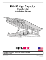
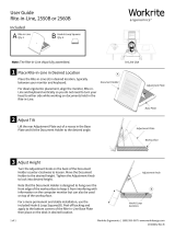
RETENTION SYSTEM INSTALLATION
3/4in [19 mm]
16in
[406 mm]
1. Mount outside wall bracket (A) on the support post
(B), 16in [406mm] from the floor to the top of the
bracket and 3/4in [19mm] from the outside of the
post with the self tap/drill screws provided.
2. Mount inside bracket (C) on the wall with angle
tight against the retention rod bolt. Make sure
mounting method will hold if panel is impacted.
3. The center of the slide rod (D) should be
approximately 3 1/2in [89mm] below the panel
eyebolt.
4. Slide eyebolt insert (E) onto cord with insert facing
up.
5. To pre-tension the spring (F), pull 6in [152mm] of
cord out, tie a knot (G) below the eyebolt insert.
6. Wrap cord around the slide collar (H) and fasten
with cable clamp (J), cut excess cord.
NOTE:
Cord should be tensioned to maintain a 3 1/2in
[89mm] gap from the panel to the wall.
C
D
B
A
H
F
E
G
J
Figure 18
Figure 17

18 Publication: AMEN00027 2017-11-06
BARRIER®GLIDER Model 7100 Installation/Owner’s Manual Rite-Hite®
ENCODER INSTALLATION
1. Finger tighten all 4 bolts on encoder mounting plate
(A) to gearbox.
2. Slide encoder non-drive sprocket (B) onto the
encoder shaft with hub out and even with the end of
the shaft and tighten set screws.
3. Slide encoder drive sprocket (C) onto the drive shaft
with hub facing out.
4. Install encoder chain (D) around sprockets.
5. Measure from each sprocket to plate aligning chain,
apply tension and tighten mounting plate bolts.
6. Tighten set screw on drive sprocket using a 3/32in
allen wrench. (Do NOT overtighten - 5in/lbs [0.56N-
m]) Sprocket does NOT require a key.
NOTE:
DO NOT TIGHTEN SET SCREWS INTO THE KEY
WAY SLOT. Set screws are not long enough to
provide a tight connection. Slippage may result.
Figure 19

Publication: AMEN00027 2017-11-06 19
Rite-Hite® BARRIER®GLIDER Model 7100 Installation/Owner’s Manual
RITE-HITE DOORS NOTES PAGE
This page intentional left blank.

1. It is the responsibility of the end user to provide
electrical service up to the control box (A) with
proper branch service protection and an approved
means of disconnect (B).
2. 20 or 30 Amp service may be required for cable
runs longer than 300ft [91M].
3. If low control box mounting is desired, mount control
box adjacent to the door at approximately 54in
[1372mm] above the floor and 14in [356mm] from
lower track.
If utilizing Graphical User Interface option (C),
mount control box near motor, however, allow room
for installing or removing motor assembly.
4. The motor and brake cables (D) are pre-wired and
must be wired to the control box.
DO NOT coil or let conduit hang on the floor.
5. If local electrical codes require the use of rigid conduit:
6. If possible, mount on the warm side regardless of
door mount side.
7. In freezer and cooler applications where a conduit
passes from a warm to cold temperature zone, the
conduit must be plugged with epoxy.
This will help prevent condensation from forming in
the conduit.
8. All holes drilled, must be through the bottom of the
box (E). Conduit entering the sides or top of the
enclosure will void the warranty.
9. Use the proper sealed connectors to maintain the
rating on the enclosure.
10. Line up pins and connect encoder cable (E) to
encoder. Verify connector is tight. DO NOT over
tighten as pins will twist. When tight, the connector
should not be able to move back and forth.
11. Incoming single or 3-phase power must connect into
fuse holder terminals F1, F2, F3 and ground
terminal.
Terminals in the control box will not accommodate
wires larger than 12AWG [2.05mm].
12. Route all field installed wires so that separation is
maintained between line voltage wires and low
voltage class II wiring.
13. The control box is provided with class CC protective
fusing for the incoming power.
14. Cut the cable tie holding the panel blower/heater
cable and route to control box. Connect cables
together at the heater / blower.
15. Refer to electrical diagrams on page 32 or 33 for
further information.
NOTE: DO NOT SPLICE CONTROL WIRING
20 Publication: AMEN00027 2017-11-06
BARRIER®GLIDER Model 7100 Installation/Owner’s Manual Rite-Hite®
ELECTRICAL INSTALLATION
When working with electrical or electronic controls, make sure
that the power source has been locked out and tagged according
to OSHA regulations and approved local electrical codes.
DANGER
!
Damage or debris may fall into electrical components causing
failure or severe equipment damage, when drilling holes in the
box.
DO NOT turn control box upside down or go too deeply into the
box.
NOTICE
Make sure to barricade the door opening on both sides to prevent
unauthorized use until the door has been completely installed.
WARNING
!
In freezer and cooler applications where a conduit passes from a
warm to cold temperature zone, the conduit must be plugged with
epoxy. This will help prevent condensation from forming in the
conduit. For more information, see Section 300-7a of the National
Electric Code.
NOTICE
Do not drill holes on top of control box to run conduit, as dust
particles and moisture may cause damage to electrical
components. The safest location is at the bottom. Failure to do so
will void warranty.
NOTICE
A qualified electrician should install the wiring in accordance with
local and national electrical codes.
Use lockout and tagout procedures to avoid injury.
DANGER
!
To reduce risk of injury or death, an earth ground connection
MUST BE made to the green/yellow control box ground
terminal. If metal conduit is used as the ground connector, an
N.E.C. approved ground bushing and green/yellow wire MUST
BE properly attached to the conduit for connection to the
ground terminal.
DANGER
!
/