© 2023 Carrier 1
BL-1001
November 17, 2023
YB110/YB230 FIREYE
BurnerLogiX
TM
Microprocessor-Based
Integrated Burner Management Control
DESCRIPTION The Fireye BurnerLogixTM System is a microprocessor-based burner management control system
designed to provide the proper burner sequencing, ignition, and flame monitoring protection on
automatically ignited oil, gas, and combination fuel burners. In conjunction with limit and
operating controls, it programs the burner/blower motor, ignition, and fuel valves to provide for
proper and safe burner operation. Through SMART LED’S, the control provides current operating
status and lockout information in the event of a safety shutdown. Optional OLED and LCD
displays are available that may be either plugged in or mounted remotely to give full language
descriptors of current status and diagnostic lockout information. Refer to BurnerLogix
PROGRAMMER SELECTION later in this document for the various combinations of
programmer and display modules.
A complete BurnerLogix system includes the YB110 (YB230) chassis equipped with the type
of flame amplifier required for the application, appropriate flame detector, plug-in programmer
module, wiring base and optional alpha-numeric display. Interchangeable programmer modules
allow for complete versatility in selection of function, timing, and flame failure response times.
The optional alpha-numeric display has 2 lines by 16 characters per line. It is available in either
vacuum fluorescent or liquid crystal formats. The advantage of OLED is high brightness and
extended temperature range down to –40°F. Both displays contain a fully functional keypad.
You can easily scroll through the various menus to view the current operating status, review
programmer configuration, and lockout history. When mounted remotely, the displays provide
NEMA 4x(IP66) protection. An advantage of the BurnerLogix control family is the ability to set
many of the operating parameters associated with proper and reliable burner operation allowing
inventory of various programmer types to be kept to a minimum.
The YB110 (YB230) is a chassis/flame amplifier module complete with mounting screws and
blank display module. The display module BLV512 (OLED) or BLL510 (LCD), if required,
must be ordered separately. Interchangeable YP programmer modules allow for complete
versatility in selection of control function, timing, and flame scanning means. Functions such as
pre-purge time, recycling or non-recycling interlocks, high fire proving interlock, and trial for
ignition timing of the pilot and main flame are determined by the programmer module. The
BurnerLogix system can be used with ultra-violet, auto-check infrared, flame rod,
self-check ultra-violet flame scanners or direct coupled integrated scanners by choosing the
proper chassis/flame amplifier module.
GEN II
GEN II

© 2023 Carrier 2
Wiring bases for the BurnerLogix control are available for easy installation or with an integral
terminal block capable of a accepting up to 2 X 14 AWG wires. The wiring base terminal block
is available with knockouts for conduit or open ended for cabinet mounting.
Additional functions of the BurnerLogix system include:
• A non-volatile memory allows the control to remember its history and present position even
when power is interrupted.
• A consistent flame signal read-out via display module or 4-20 mA output.
• Read-out of main fuel operational hours and complete cycles via display module.
• Modbus communications via RS485 multi-drop link.
• Proof of fuel valve closure during the off cycle.
• Burn-in time of program parameters occurs after 8 hours of main valve on time.
• A run/check switch allows the operator to stop the program sequence in any of four different
positions (Purge, PTFI, MTFI or Auto).
• Remote Display mounting with NEMA 4 protection.
• Remote Reset.
• Programmable communication baud rate allows for DCS compatibility.
• Keypad selectable language readout.
• Revert to pilot can increase burner turn down.
• Additional terminals provided for applications requiring additional inputs and outputs.
• Fuel Selection switch.
• Intelligent valve proving feature for two-valve systems only.
• Low Gas Pressure Check feature.
• Burner On/Off through Keypad.
CAUTION: While programmers are mechanically interchangeable in that they mate
with a common chassis/amplifier module, you must select the correct model for your
application. Inappropriate application of a control can result in an unsafe condition
hazardous to life and property. Selection of a control for a particular application must
be made by a competent professional, such as a boiler/burner service technician
licensed by a state or other government agency.
NOTICE: This equipment generates and can radiate radio frequency energy, and if
not installed and used in accordance with the instruction manual may cause
interference to radio communications. It has been tested and found to comply with the
limits for a Class A computing device pursuant to Subpart J of part 15 of FCC Rules,
which are designed to provide reasonable protection against such interference when
operated in a commercial environment. Operation of this equipment in a residential
area may cause interference in which case the user, at his own expense, will be required
to take whatever measures which may be required to correct the interference.

© 2023 Carrier 3
Table of Contents
DESCRIPTION ........................................................................................................................................................ 1
BURNERLOGIX SPECIFICATIONS ........................................................................................................................ 6
PART NUMBERS AND APPROVALS ..................................................................................................................... 9
ORDERING INFORMATION .................................................................................................................................. 10
INSTALLATION PROCEDURE .............................................................................................................................. 13
WIRING BASE ................................................................................................................................................... 14
PTFI*MTFI TIMINGS ......................................................................................................................................... 18
LED INDICATOR LIGHTS ................................................................................................................................. 20
REPLACEABLE FUSE ...................................................................................................................................... 21
OPERATING CONTROL FUNCTIONS.................................................................................................................. 22
SETTING PROGRAMMER PARAMETERS .......................................................................................................... 22
KEYPAD DESCRIPTION ................................................................................................................................... 23
PROGRAM SET UP SUB-MENU .......................................................................................................................... 24
TO VIEW AND MODIFY A PROGRAMMABLE PARAMETER: ......................................................................... 26
FLAME SCANNERS .............................................................................................................................................. 26
INSTALLATION - UV SCANNERS .................................................................................................................... 27
OPERATION — 45UV5 & 55UV5 SELF-CHECKING UV SCANNER ............................................................... 28
WIRING - UV SCANNERS ................................................................................................................................ 29
INSTALLATION—INFRARED SCANNER TYPE 48PT2 ................................................................................... 29
OPERATION - IR LEARN .................................................................................................................................. 30
INSTALLATION - 69ND1 FLAME ROD ............................................................................................................. 32
INSTALLATION - 85 SERIES PHOENIX SCANNER ........................................................................................ 33
INSTALLATION - 95 SERIES INSIGHT SCANNERS........................................................................................ 35
SYSTEM INFO SUB-MENU ................................................................................................................................... 38
SYSTEM OPERATION .......................................................................................................................................... 38
YP100 OPERATING SEQUENCE ..................................................................................................................... 39
START-UP (NORMAL CYCLE) ......................................................................................................................... 40
YP200 OPERATING SEQUENCE ..................................................................................................................... 42
YP300 OPERATING SEQUENCE ..................................................................................................................... 43
YP138 PROGRAMMER .................................................................................................................................... 46
YP148 PROGRAMMER .................................................................................................................................... 49
LOCKOUTS ........................................................................................................................................................... 53
SAFETY SHUTDOWN ....................................................................................................................................... 53
DIAGNOSTIC MESSAGES ............................................................................................................................... 54
RESETTING THE CONTROL............................................................................................................................ 54
LOCKOUT CODES ............................................................................................................................................ 56
LOCKOUT HISTORY SUB-MENU .................................................................................................................... 57
COMMUNICATIONS.............................................................................................................................................. 58
MESSAGE FORMAT ......................................................................................................................................... 58
MODBUS MESSAGE TABLE ............................................................................................................................ 59
INPUTS.............................................................................................................................................................. 60
OUTPUTS .......................................................................................................................................................... 61
EXPLANATION OF LOGSTAT .......................................................................................................................... 62
BURNERLOGIX MESSAGES............................................................................................................................ 63
INTERLOCK ANNUNCIATOR ........................................................................................................................... 65
OPERATIONAL FEATURES ................................................................................................................................. 66

© 2023 Carrier 4
4-20 mA TEST JACKS ...................................................................................................................................... 66
CHECK RUN SWITCH ...................................................................................................................................... 67
VALVE PROVING .............................................................................................................................................. 68
OPERATIONAL TEST ........................................................................................................................................... 72
TEST CHECKOUT PROCEDURES .................................................................................................................. 72
BURNERLOGIX GROUNDING RULES ............................................................................................................ 74
MAINTENANCE ................................................................................................................................................. 75
NOTICE ................................................................................................................................................................. 78
WARRANTIES ....................................................................................................................................................... 78

© 2023 Carrier 5
Table of Figures
FIGURE 1.
BURNERLOGIX ORDERING INFORMATION . . . . . . . . . . . . . . . . . . . . . . . . . . . . . . . . . . . . . . . . . . . . . . . . . . . . . . . . . . .
13
FIGURE 2.
WIRING BASE DETAILS. . . . . . . . . . . . . . . . . . . . . . . . . . . . . . . . . . . . . . . . . . . . . . . . . . . . . . . . . . . . . . . . . . . . . . . . . . . . .
14
FIGURE 3.
YP110 PROGRAMMER . . . . . . . . . . . . . . . . . . . . . . . . . . . . . . . . . . . . . . . . . . . . . . . . . . . . . . . . . . . . . . . . . . . . . . . . . . . . . .
16
FIGURE 4.
KEYPAD DESCRIPTION . . . . . . . . . . . . . . . . . . . . . . . . . . . . . . . . . . . . . . . . . . . . . . . . . . . . . . . . . . . . . . . . . . . . . . . . . . . . .
23
FIGURE 5.
BURNERLOGIX MENU STRUCTURE . . . . . . . . . . . . . . . . . . . . . . . . . . . . . . . . . . . . . . . . . . . . . . . . . . . . . . . . . . . . . . . . .
23
FIGURE 6.
MAIN MENU. . . . . . . . . . . . . . . . . . . . . . . . . . . . . . . . . . . . . . . . . . . . . . . . . . . . . . . . . . . . . . . . . . . . . . . . . . . . . . . . . . . . . . .
24
FIGURE 7.
FLAME SCANNERS. . . . . . . . . . . . . . . . . . . . . . . . . . . . . . . . . . . . . . . . . . . . . . . . . . . . . . . . . . . . . . . . . . . . . . . . . . . . . . . . .
26
FIGURE 8.
AIMING YOUR SCANNER . . . . . . . . . . . . . . . . . . . . . . . . . . . . . . . . . . . . . . . . . . . . . . . . . . . . . . . . . . . . . . . . . . . . . . . . . . ..
27
FIGURE 9.
TYPICAL SCANNER INSTALLATIONS . . . . . . . . . . . . . . . . . . . . . . . . . . . . . . . . . . . . . . . . . . . . . . . . . . . . . . . . . . . . . . . .
28
FIGURE 10.
UV SELF CHECK SCANNER OPERATION . . . . . . . . . . . . . . . . . . . . . . . . . . . . . . . . . . . . . . . . . . . . . . . . . . . . . . . . . . . . .
28
FIGURE 11.
SCANNER INSTALLATION . . . . . . . . . . . . . . . . . . . . . . . . . . . . . . . . . . . . . . . . . . . . . . . . . . . . . . . . . . . . . . . . . . . . . . . . . .
29
FIGURE 12.
PHOENIX WIRING DIAGRAM . . . . . . . . . . . . . . . . . . . . . . . . . . . . . . . . . . . . . . . . . . . . . . . . . . . . . . . . . . . . . . . . . . . . . . .
33
FIGURE 13.
BURNERLOGIX TYB110DC/YB230DC WITH 85UVF4-1QDWR SCANNER . . . . . . . . . . . . . . . . . . . . . . . . . . . . . . . . . .
34
FIGURE 14.
INSIGHT WIRING DIAGRAM . . . . . . . . . . . . . . . . . . . . . . . . . . . . . . . . . . . . . . . . . . . . . . . . . . . . . . . . . . . . . . . . . . . . . . . .
36
FIGURE 15.
CONNECT BURNERLOGIX & INSIGHT I . . . . . . . . . . . . . . . . . . . . . . . . . . . . . . . . . . . . . . . . . . . . . . . . . . . . . . . . . . . . . .
37
FIGURE 16.
SYSTEM INFO SUB-MENU . . . . . . . . . . . . . . . . . . . . . . . . . . . . . . . . . . . . . . . . . . . . . . . . . . . . . . . . . . . . . . . . . . . . . . . . . .
38
FIGURE 17.
YP100 OPERATING SEQUENCE . . . . . . . . . . . . . . . . . . . . . . . . . . . . . . . . . . . . . . . . . . . . . . . . . . . . . . . . . . . . . . . . . . . . . .
39
FIGURE 18.
YP200 OPERATING SEQUENCE . . . . . . . . . . . . . . . . . . . . . . . . . . . . . . . . . . . . . . . . . . . . . . . . . . . . . . . . . . . . . . . . . . . . . .
42
FIGURE 19.
YP300 OPERATING SEQUENCE . . . . . . . . . . . . . . . . . . . . . . . . . . . . . . . . . . . . . . . . . . . . . . . . . . . . . . . . . . . . . . . . . . . . . .
43
FIGURE 20.
YP148 OPERATING SEQUENCE DISABLED. . . . . . . . . . . . . . . . . . . . . . . . . . . . . . . . . . . . . . . . . . . . . . . . . . . . . . . . . . . .
44
FIGURE 21.
YP148 OPERATING SEQUENCE ENABLED . . . . . . . . . . . . . . . . . . . . . . . . . . . . . . . . . . . . . . . . . . . . . . . . . . . . . . . . . . . .
44
FIGURE 22
BURNERLOGIX WIRING DIAGRAM . . . . . . . . . . . . . . . . . . . . . . . . . . . . . . . . . . . . . . . . . . . . . . . . . . . . . . . . . . . . . . . . . .
45
FIGURE 23
YP300 WIRING DIAGRAM . . . . . . . . . . . . . . . . . . . . . . . . . . . . . . . . . . . . . . . . . . . . . . . . . . . . . . . . . . . . . . . . . . . . . . . . . . .
46
FIGURE 24
YP138 WIRING DIAGRAM . . . . . . . . . . . . . . . . . . . . . . . . . . . . . . . . . . . . . . . . . . . . . . . . . . . . . . . . . . . . . . . . . . . . . . . . . . .
47
FIGURE 25
YP148 WIRING DIAGRAM . . . . . . . . . . . . . . . . . . . . . . . . . . . . . . . . . . . . . . . . . . . . . . . . . . . . . . . . . . . . . . . . . . . . . . . . . . .
50
FIGURE 26
LOCKOUT HISTORY . . . . . . . . . . . . . . . . . . . . . . . . . . . . . . . . . . . . . . . . . . . . . . . . . . . . . . . . . . . . . . . . . . . . . . . . . . . . . . . .
57
FIGURE.27
BOTTOM VIEW COMMS . . . . . . . . . . . . . . . . . . . . . . . . . . . . . . . . . . . . . . . . . . . . . . . . . . . . . . . . . . . . . . . . . . . . . . . . . . . .
58
FIGURE.28
DEFAULT WIRING FOR YZ300 INTERLOCK ANNUNCIATOR . . . . . . . . . . . . . . . . . . . . . . . . . . . . . . . . . . . . . . . . . . . .
61
FIGURE.29
BOTTOM VIEW 4-20 mA JACKS . . . . . . . . . . . . . . . . . . . . . . . . . . . . . . . . . . . . . . . . . . . . . . . . . . . . . . . . . . . . . . . . . . . . . .
66
FIGURE.30
TEST JACKS (4-20 mA) VS. FLAME STRENGTH . . . . . . . . . . . . . . . . . . . . . . . . . . . . . . . . . . . . . . . . . . . . . . . . . . . . . . . .
66
FIGURE.31
CHECK RUN SWITCH . . . . . . . . . . . . . . . . . . . . . . . . . . . . . . . . . . . . . . . . . . . . . . . . . . . . . . . . . . . . . . . . . . . . . . . . . . . . .
67
FIGURE.32
PILOT FLAME TEST . . . . . . . . . . . . . . . . . . . . . . . . . . . . . . . . . . . . . . . . . . . . . . . . . . . . . . . . . . . . . . . . . . . . . . . . . . . . . . . .
74
Table of Tables
Table 1:
OPERATING TEMPERATURE LIMITS . . . . . . . . . . . . . . . . . . . . . . . . . . . . . . . . . . . . . . . . . . . . . . . . . . . . . . . . . . . . . . . . . .
6
Table 2:
LOAD RATINGS . . . . . . . . . . . . . . . . . . . . . . . . . . . . . . . . . . . . . . . . . . . . . . . . . . . . . . . . . . . . . . . . . . . . . . . . . . . . . . . . . . . .
7
Table 3:
AGENCY APPROVALS . . . . . . . . . . . . . . . . . . . . . . . . . . . . . . . . . . . . . . . . . . . . . . . . . . . . . . . . . . . . . . . . . . . . . . . . . . . . . . .
9
Table 4:
APPLICABLE BULLETINS . . . . . . . . . . . . . . . . . . . . . . . . . . . . . . . . . . . . . . . . . . . . . . . . . . . . . . . . . . . . . . . . . . . . . . . . . . . .
10
Table 5:
ORDERING INFORMATION. . . . . . . . . . . . . . . . . . . . . . . . . . . . . . . . . . . . . . . . . . . . . . . . . . . . . . . . . . . . . . . . . . . . . . . . . . .
10
Table 6:
PROGRAMMER MODULES . . . . . . . . . . . . . . . . . . . . . . . . . . . . . . . . . . . . . . . . . . . . . . . . . . . . . . . . . . . . . . . . . . . . . . . . . . .
10
Table 7:
BURNERLOGIX DISPLAYS . . . . . . . . . . . . . . . . . . . . . . . . . . . . . . . . . . . . . . . . . . . . . . . . . . . . . . . . . . . . . . . . . . . . . . . . . .
11
Table 8:
BURNERLOGIX WIRING BASES . . . . . . . . . . . . . . . . . . . . . . . . . . . . . . . . . . . . . . . . . . . . . . . . . . . . . . . . . . . . . . . . . . . . .
11
Table 9:
BURNERLOGIX ACCESSORIES . . . . . . . . . . . . . . . . . . . . . . . . . . . . . . . . . . . . . . . . . . . . . . . . . . . . . . . . . . . . . . . . . . . . . .
11
Table 10:
SCANNER SELECTION. . . . . . . . . . . . . . . . . . . . . . . . . . . . . . . . . . . . . . . . . . . . . . . . . . . . . . . . . . . . . . . . . . . . . . . . . . . . . .
11
Table 11:
PRE-WIRED WIRING BASE, P/N 60-2810-1 (shown for 120 VAC) . . . . . . . . . . . . . . . . . . . . . . . . . . . . . . . . . . . . . . . . . . .
14
Table 12:
BURNERLOGIX PROGRAMMER SELECTION . . . . . . . . . . . . . . . . . . . . . . . . . . . . . . . . . . . . . . . . . . . . . . . . . . . . . . . . . .
17
Table 13:
PTFI & MTFI TIMING . . . . . . . . . . . . . . . . . . . . . . . . . . . . . . . . . . . . . . . . . . . . . . . . . . . . . . . . . . . . . . . . . . . . . . . . . . . . . . .
19
Table 14:
LED INDICATORS . . . . . . . . . . . . . . . . . . . . . . . . . . . . . . . . . . . . . . . . . . . . . . . . . . . . . . . . . . . . . . . . . . . . . . . . . . . . . . . . . .
20
Table 15:
MODIFIABLE PARAMETERS LOCATED IN PROGRAM SETUP MENU . . . . . . . . . . . . . . . . . . . . . . . . . . . . . . . . . . . . .
25
Table 16:
PHOENIX SCANNER CABLE COLOR CODE . . . . . . . . . . . . . . . . . . . . . . . . . . . . . . . . . . . . . . . . . . . . . . . . . . . . . . . . . . .
34
Table 17:
DIAGNOSTIC MESSAGES . . . . . . . . . . . . . . . . . . . . . . . . . . . . . . . . . . . . . . . . . . . . . . . . . . . . . . . . . . . . . . . . . . . . . . . . . . .
54
Table 18:
LED CODES . . . . . . . . . . . . . . . . . . . . . . . . . . . . . . . . . . . . . . . . . . . . . . . . . . . . . . . . . . . . . . . . . . . . . . . . . . . . . . . . . . . . . . .
56
Table 19:
MESSAGE FORMAT . . . . . . . . . . . . . . . . . . . . . . . . . . . . . . . . . . . . . . . . . . . . . . . . . . . . . . . . . . . . . . . . . . . . . . . . . . . . . . . .
58
Table 20:
MODBUS . . . . . . . . . . . . . . . . . . . . . . . . . . . . . . . . . . . . . . . . . . . . . . . . . . . . . . . . . . . . . . . . . . . . . . . . . . . . . . . . . . . . . . . . . .
58
Table 21:
MODBUS MESSAGE TABLE . . . . . . . . . . . . . . . . . . . . . . . . . . . . . . . . . . . . . . . . . . . . . . . . . . . . . . . . . . . . . . . . . . . . . . . . .
59
Table 22:
INPUTS AND OUTPUTS . . . . . . . . . . . . . . . . . . . . . . . . . . . . . . . . . . . . . . . . . . . . . . . . . . . . . . . . . . . . . . . . . . . . . . . . . . . . .
60
Table 23:
YZ300. . . . . . . . . . . . . . . . . . . . . . . . . . . . . . . . . . . . . . . . . . . . . . . . . . . . . . . . . . . . . . . . . . . . . . . . . . . . . . . . . . . . . . . . . . . . .
61
Table 24:
LOGSTAT. . . . . . . . . . . . . . . . . . . . . . . . . . . . . . . . . . . . . . . . . . . . . . . . . . . . . . . . . . . . . . . . . . . . . . . . . . . . . . . . . . . . . . . . . .
62
Table 25:
BURNERLOGIX MESSAGES . . . . . . . . . . . . . . . . . . . . . . . . . . . . . . . . . . . . . . . . . . . . . . . . . . . . . . . . . . . . . . . . . . . . . . . . .
63
Table 26:
DIAGNOSTIC MESSAGES . . . . . . . . . . . . . . . . . . . . . . . . . . . . . . . . . . . . . . . . . . . . . . . . . . . . . . . . . . . . . . . . . . . . . . . . . . .
64
Table 27:
ANNUNCIATOR MESSAGES . . . . . . . . . . . . . . . . . . . . . . . . . . . . . . . . . . . . . . . . . . . . . . . . . . . . . . . . . . . . . . . . . . . . . . . . .
65

© 2023 Carrier 6
BURNERLOGIX SPECIFICATIONS
Supply Voltage:
YB110 120 VAC (+10%, -15%) 50/60 Hz
YB230 230 VAC (+10%, -15%) 50/60 Hz
Power Consumption:
25 VA
Temperature Rating:
-40°C (-40°F) to +60°C (140°F)
Protection Category:
YB110 (YB230) control NEMA 1 (IP01)
Display, remote mounted NEMA 4X (IP66)
Unit Dimensions:
Wiring base 60-2812-1, 60-2814-1 - 4.0" (101 mm) W x 7.0" (178 mm) H
Shipping Weight:
YB110 (YB230) Approx. 3.2 lbs. (1.45kg)
Table 1: OPERATING TEMPERATURE LIMITS
CONTROL
MAXIMUM
MINIMUM
YB110, YB230
140°F
60°C
-40°F
-40°C
YP Programmers
140°F
60°C
-40°F
-40°C
BLV512, OLED Display
140°F
60°C
-40°F
-40°C
BLL510, LCD Display
140°F
60°C
-4°F
-20°C
Scanner UV1A, UV2, UV8A, UV90, 45UV3
200°F
93°C
-40°F
-40°C
45UV5-1005, 45UV5-1105
45UV5-1007, 45UV5-1009
55UV5-1007, 55UV5-1009
200°F
93°C
-40°F
-40°C
48PT2
140°F
60°C
-40°F
-40°C
Flame Rod (Tip 2460°F)
1500°F
816°C
-40°F
-40°C
Humidity: 90% R.H. (Non-condensing)
Phoenix 85 Series
150°F
65°C
-40°F
-40°C
InSight 95 Series
150°F
65°C
-40°F
-40°C

© 2023 Carrier 7
Table 2: LOAD RATINGS
Terminal
Typical Load
A. Maximum Rating
@120V-50/60 Hz
B. Maximum Rating
@230V-50/60 Hz
C. Alternate Rating
M
Burner/Blower Motor
9.8 F.L.A. *
58 L.R.A.
4.0 F.L.A. *
20 L.R.A.
240 VA Pilot Duty
(Motor Starter Coil)
10-11-12-X
Modulator
125 VA Pilot Duty
A
Alarm
50 VA Pilot Duty
Terminal ratings may be selected from either column A or C for 120 VAC or from either column B or C for 30 VAC:
(select the rating from the column which best applies to the connected load on that terminal).
* F.L.A. = full load amps; L.R.A = locked rotor amps
Combination of fuel and igniter terminals
Combination No.
Pilot Fuel
Trm 6
Main
Trm 7
Ignition
Trm 5
Delayed Valve
Trm W
1
C
E
No Load
No Load
2
B
E
No Load
No Load
3
No Load
E
No Load
B
4
E
E
A
No Load
5
No Load
E
A
E
6
D
E
A
No Load
7
D
D
A
D
8
No Load
D
A
No Load
For YP148/YP184 programmers, Ignition (Terminal W) - 4.5 A, Pilot (Terminal 5) - 2A Pilot Duty,
Main Valve 1 (Terminal 6) - 2A Pilot Duty, Main Valve 2 (Terminal 7) - 2A Pilot Duty
Refer YP148/YP184 wiring diagram for more details on terminals.
Composition of each combination
A
B
C
D
E
4.5A Ignition
@120 VAC
50 VA Pilot Duty
plus 4.5A ignition@
120 VAC
180 VA Ignition plus
motor valves with: 660
VA inrush, 360 VA
open, 250 VA hold.
2A Pilot Duty
@120 VAC
65 VA Pilot Duty plus
Motor valves with: 700
VA open 250 VA hold.
2.2A Ignition
@230 VAC
50 VA Pilot Duty
plus 2.2A ignition
@230 VAC
1A Pilot Duty
@230 VAC
Maximum connected load must not exceed 2000 VA
ELECTRICAL RATINGS
VA ratings (not specified as pilot duty) permit the connection of transformers and similar
devices whose inrush current is approximately the same as their running current.
VA Pilot Duty ratings permit the connection of relays, solenoid valves, lamps, etc. who’s total
operating load does not exceed the published rating and whose total inrush current does not
exceed 10 times the rating.
Running and locked rotor ratings are intended for motors. VA and VA Pilot Duty loads may be
added to a motor load provided the total load does not exceed the published rating.

© 2023 Carrier 8
CAUTION: Published load ratings assume that no contact will be required to handle
inrush current more often than once in 15 seconds. Using control switches, solenoid,
relays, etc. which chatter lead to premature failure. Run through a test operation
(with fuel shut off) following the tripping of a circuit breaker, a blown fuse, or any
known instance of chattering of any external current consuming devices.
APPROVALS
Underwriters Laboratories Inc.:
MCCZ File MP1537
Controls, Primary Safety - Listed
MCCZ2 File MP1537
Controls, Primary Safety - Component
MCCZ7 File MP1537
Controls, Primary Safety Certified for Canada
MCCZ8 File MP1537
Controls, Primary Safety Certified for Canada - Component
Factory Mutual: Approved
Acceptable by: Industrial Risk Insurers (I.R.I.)
CE:
Gas Appliances
Gas Appliance
Directive:
90/396/EEC
Low Voltage
Directive:
73/23/EEC
EMC Directive:
89/336/EEC
GASTEC:
0063BT1754
(EN298, 2003; EN230, 2005)
NOTICE: This equipment generates and can radiate radio frequency energy, and
if not installed and used in accordance with the instruction manual may cause
interference to radio communications. It has been tested and found to comply
with the limits for a Class A computing device pursuant to Subpart J of part 15
of FCC Rules, which are designed to provide reasonable protection against such
interference when operated in a commercial environment. Operation of this
equipment in a residential area may cause interference in which case the user,
at his own expense, is required to take whatever measures which may be
required to correct the interference.

© 2023 Carrier 9
PART NUMBERS AND APPROVALS
Table 3: AGENCY APPROVALS
BurnerLogix
Chassis/Flame Amp. Module
YB110UV
X
X
YB110UVSC
X
X
YB110IR
X
X
YB110IR2
X
X
YB110FR
X
X
YB110DC
X
X
YB230UV
X
YB230UVSC
X
YB230IR
X
YB230IR2
X
YB230FR
X
YB230DC
X
BurnerLogix Programmer Module
YP100
X
X
YP102
X
X
YP138
X
X
YP118
X
X
YP183
X
X
YP200
X
X
YP202
X
X
YP300
X
X
YP302
X
X
YP113
X
X
YP115
X
X
YP148
X
YP184
X
BurnerLogix Displays
BLV512
X
X
X
BLL510
X
X
X
BurnerLogix Wiring Bases
60-2812-1
X
X
60-2814-1
X
X
X = CERTIFICATION IN HAND

© 2023 Carrier 10
Table 4: APPLICABLE BULLETINS
Programmers, Non-recycle Operation
YP-1001
Programmers, Recycle Operation
Programmers, Non-modulating
Displays
BD-5001
Wiring base installation, 60-2812-1
133-677
Wiring base installation, 60-2814-1
133-677
ORDERING INFORMATION
Table 5:
BurnerLogix Chassis/Flame Amplifier Module
YB110UV
120 VAC input with UV non-self-check amplifier
YB110UVSC
120 VAC input with UV self-check amplifier
YB110IR
120 VAC input with IR auto-check amplifier
YB110IR2
120 VAC input with IR auto-check amplifier (special application only -consult factory)
YB110FR
120 VAC input with flame rectification amplifier
YB110DC
120 VAC input with direct coupled amplifier
YB230UV
230 VAC input with UV non-self-check amplifier
YB230UVSC
230 VAC input with UV self-check amplifier
YB230IR
230 VAC input with IR auto-check amplifier
YB230IR2
230 VAC input with IR auto check (special application only-consult factory)
YB230FR
230VAC input with flame rectification amplifier
YB230DC
230VAC input with direct coupled amplifier
Table 6: PROGRAMMER MODULES
BurnerLogix Programmer Modules
YP100
Keypad selectable parameters, non-recycle operation, modulation, open damper proving, 4 second FFRT
YP102
Keypad selectable parameters, non-recycle operation, modulation, open damper proving, 2 second FFRT
YP113
Keypad selectable parameters, non-recycle operation, modulation, open damper proving, 1 second FFRT
YP115
Keypad selectable parameters, non-recycle operation, modulation, open damper proving, 1 second FFRT
YP118
Keypad selectable parameters, non-recycle operation, modulation, open damper proving, indefinite pilot hold, revert to
pilot from auto, 1 second FFRT
YP138
Keypad selectable parameters, non-recycle operation, modulation, open damper proving, voltage on terminal 16 is indefinite pilot
hold during light-off, applied voltage on term 16 is revert to pilot from auto, 4 second FFRT
YP183
Same as YP138, except, removal of voltage on terminal 16 will suspend pilot hold during light-off sequence. Terminal W used
for purge complete.
YP200
Keypad selectable parameters, recycle operation, modulation, 4 second FFRT
YP202
Keypad selectable parameters, recycle operation, modulation, 2 second FFRT
YP300
Keypad selectable parameters, recycle operation, low fire start, early spark termination, 4 second FFRT
YP302
Keypad selectable parameters, recycle operation, low fire start, early spark termination, 2 second FFRT
YP148
Keypad selectable parameters, non-recycle operation, modulation, open damper proving, fuel selection switch, valve proving,
low gas pressure check (active high), Burner On/Off through Keypad, 4 second FFRT.
YP184
Same as YP148, except low gas pressure check (active low).
Note: All programmers: when used with the YB110DC or YB230DC, the FFRT is 0.3 seconds

© 2023 Carrier 11
Table 7: BURNERLOGIX DISPLAYS
BurnerLogix Displays
BLV512
Display, 2-line X 16 characters, OLED, with cable, NEMA 4
BLL510
Display, 2-line X 16 characters, LCD, with cable, NEMA 4
Table 8: BURNERLOGIX WIRING BASES
BurnerLogix wiring bases
60-2812-1
Closed base with terminal block and knockouts, 4"W x 7"H
60-2814-1
Open base with terminal block. 4"W x 7"H
Table 9: BURNERLOGIX ACCESSORIES
BurnerLogix Accessories
129-178-4
Kit, remote mounting, BurnerLogix display, 4 ft. cable, provides NEMA 4 protection
129-178-8
Kit, remote mounting, BurnerLogix display, 8 ft. cable, provides NEMA 4 protection
BLD500
Blank display module, included with YB module
IT1000
Alarm annunciation system using wireless technology
PPC6000
Parallel Positioning System
61-5745-3
Shutter drive assembly for redundant self-check scanners
Table 10: SCANNER SELECTION
FIREYE P/N
DESCRIPTION
USE WITH CHASSIS
BULLETIN
48PT2-1003
48PT2-9003
48PT2-1007
48PT2-9007
4-263-1
Infrared 1/2" straight mount 96"(2438mm) TC-ER cable
Infrared 1/2" 90° angle mount 96" (2438mm) TC-ER
cable Infrared 1/2" straight mount 48" (1219mm) TC-ER
cable Infrared 1/2" 90° angle mount 48" (1219mm) TC-
ER cable Replacement photo detector
YB110IR
YB230IR
YB110IR2
YB230IR2
SC-103
UV1A3
UV1A6
UV8A
UV2
UV2A6
45UV3-1050
UV90-3
UV90-6
UV90-9
UV 1/2" straight 36" (915mm) TC-ER cable
UV 1/2" straight 72" (1830mm) TC-ER cable
UV 1/2" 90° head 72" (1830mm) no armor flex
UV 3/8" straight 36"(915mm) TC-ER cable
UV 3/8" straight 72" (1830mm) TC-ER cable
UV 3/4" cast aluminum housing 96" (2438mm) unshielded leads
UV 90° lateral view with 36" (915mm) flex conduit
UV 90° lateral view with 72" (1830mm) flex conduit
UV 90° lateral view with 108" (2745mm) flex conduit
YB110UV
YB230UV
SC-102
45UV5-1007
45UV5-1009
4-314-1
Self-check UV 1" BSP threads, 102-
264VAC Self-check UV 1" NPT threads,
102-264VAC Replacement UV tube
YB110UVSC
YB230UVSC
SC-101
69ND1-1000K4
69ND1-1000K6
69ND1-1000K8
Flame rod, 12”, 1/2” mount
Flame rod, 18”, 1/2” mount
Flame rod, 24”, 1/2” mount
YB110FR
YB230FR
SC-103
45UV5-1005
45UV5-1105
Self-check UV 1" NPT threads, 61-5745-3 required
Self-check UV 1" BSP threads, 61-5745-3 required
YB110UVSC
YB230UVSC
133-645

© 2023 Carrier 12
55UV5-1007
55UV5-1009
Self-check UV 1" BSP, 102-264VAC, Suitable for hazardous locations. Self-
check UV 1" NPT, 102-264VAC, Suitable for hazardous locations.
YB110UVSC
YB230UVSC
SC-106
PHOENIX
FIREYE P/N
DESCRIPTION
USE WITH
CHASSIS
BULLETIN
85UVF4-1QDWR
85UVF4-2QDWR
85IRF4-1QDWR
85IRF4-2QDWR
Phoenix Integrated Scanner, 4 sec FFRT – Ultra-violet with 8-pin electrical quick
disconnect. FM, UL_CUS approved.
Fiber optic version of standard Phoenix Integrated Scanner, 4 sec FFRT – Ultra-violet
with 8-pin electrical quick disconnect. FM, UL_CUS approved.
Phoenix Integrated Scanner, 4 sec FFRT – Infrared with 8-pin electrical quick
disconnect. FM, UL_CUS approved.
Fiber optic version of standard Phoenix Integrated Scanner, 4 sec FFRT – Infrared
with 8-pin electrical quick disconnect. FM, UL_CUS approved.
YB110DC
YB230DC
CU-114
35-318-1
35-318-2
Mounting flange for Phoenix, 1“ NPT
Mounting flange for Phoenix, 1“ BSP
59-546-3
59-546-6
59-546-9
59-546-12
59-546-15
59-546-30
59-546-45
59-546-60
59-546-90
8-Conductor 3-meter (9 ft. 10 in.) cable assembly with 8-pin female connector.
8-Conductor 6-meter (19 ft. 8 in.) cable assembly with 8-pin female connector.
8-Conductor 9-meter (29 ft. 3 in.) cable assembly with 8-pin female connector.
8-Conductor 12-meter (39 ft. 4 in.) cable assembly with 8-pin female connector.
8-Conductor 15-meter (49 ft. 2 in.) cable assembly with 8-pin female connector.
8-Conductor 30-meter (98 ft. 5 in.) cable assembly with 8-pin female connector.
8-Conductor 45-meter (147 ft. 7 in.) cable assembly with 8-pin female connector.
8-Conductor 60-meter (196 ft. 10 in.) cable assembly with 8-pin female connector.
8-Conductor 90-meter (295 ft. 3 in.) cable assembly with 8-pin female connector.
INSIGHT
95IRS2-1, 2
95UVS2-1, 2, 3
95DSS2-1
Enhanced Model InSight Scanner – Infrared with quick disconnect,
FM, UL_CUS approved.
Enhanced Model InSight Scanner – Ultra-violet with quick disconnect,
FM, UL_CUS approved.
Enhanced Model InSight Scanner – Dual detector with quick disconnect,
FM, UL_CUS approved.
YB110DC
YB230DC
CU-95
60-2692
60-2693
1” NPT mounting flange for InSight Scanner, includes heat insulator 35127-1.
1” BSP mounting flange for InSight Scanner, includes heat insulator 35- 127-3.
59-497-020- WR
59-497-020C - WR
59-497-020R-WR
59-497-020RC-WR
12-Conductor cable with straight connector (129-164), 20 feet (6 meter)
12-Conductor cable with straight connector (129-164C) and flex conduit adapter,
20 feet (6 meter)
12-Conductor cable with right angle connector (129-164R), 20 feet (6 meter)
12-Conductor cable with right angle connector (129-164RC) and flex conduit
adapter, 20 feet (6 meter)
POWER SUPPLIES
60-2685-25
60-2685-50
Power Supply, 24 VDC, 2.0A, 120/240 VAC, 50/60Hz
Power Supply, 24 VDC, 4.0A, 120/240 VAC, 50/60Hz
CU-118

© 2023 Carrier 13
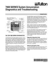
FRONT VIEW
(WITH OPTIONAL DISPLAY INSTALLED)
Figure 1. BURNERLOGIX ORDERING INFORMATION
60-2812-1
PROGRAMMER MODULE
YP100
YP102
YP200
YP202
YP300
YP302
YP113
YP138
YP118
YP148
YP184
DISPLAY MODULE
BLV512 - OLED
BLL510 - LIQUID CRYSTAL
NOTE: The Phoenix QDWR models with electrical quick-disconnect have replaced the original WR
models equipped with ten feet of captive cable. The QDWR models (with 59-546-X cables) are also
suitable for use in Class I Division 2 hazardous areas, thereby eliminating the need for the “EXWR” models.
CHASSIS/AMPLIFIER
120 VAC, 50/60 Hz
YB110UV
YB110UVSC
YB110IR
YB110FR
YB110DC
230 VAC, 50/60 Hz
YB230UV
YB230 UVSC
YB230IR
YB23FR
YB230DC
FRONT VIEW SIDE VIEW
(WITH OPTIONAL DISPLAY INSTALLED) (WITH OPTIONAL PROGRAMMER AND DISPLAY INSTALLED)
GEN II
GEN II
GEN II
GEN II

© 2023 Carrier 14
INSTALLATION PROCEDURE
WIRING BASE
Select either the terminal block style (60-2812-1, 60-2814-1). Either wiring base type can be mounted on
a din rail or directly mounted to the cabinet back plate. Refer to Figure 2 for mounting dimensions.
Figure 2. WIRING BASE DETAILS
The location should be free from excessive vibration and within the ambient temperature rating.
Table 11: PRE-WIRED WIRING BASE, P/N 60-2810-1 (shown for 120 VAC)
Terminal No.
Type
Description
Rating
L1 (Hot)
Line voltage supply
120/230 VAC (+10%,-15%), 50/60 Hz
L2 (Neutral)
Line voltage common
EARTH
Ground
S1
Scanner Input
300 VAC, 3 mA (UV models only)
S2
Scanner Input
300 VAC, 3 mA (UV models only)
A
Output
Alarm
120/230 VAC, 1 A pilot duty
M
Output
Combustion Blower
120/230 VAC, 9.8 FLA, 58.8 LRA
3
Input
Operating Control
120/230 VAC, 1 mA
13
Input
Fuel Valve End Switch, Pre-Ignition Interlock
120/230 VAC, 1 mA
P
Input
Running Interlock
120/230 VAC, 1 mA
D
Input
Low Fire Start Switch
120/230 VAC, 1 mA
8
Input
High Fire Purge Interlock
120/230 VAC, 1 mA
W
Output
Delayed Main Valve YP300 programmer only
See Load Ratings (Page 7)
Ignition (Applies to YP148, YP184 programmers only)
See Load Ratings (Page 7)
5
Output
Ignition / Pilot Valve
See Load Ratings (Page 7)
Pilot Valve (Applies to YP148, YP184 programmers only)
See Load Ratings (Page 7)
6
Output
Pilot Valve
See Load Ratings (Page 7)
Main Valve 1 (Applies to YP148, YP184 programmers only)
See Load Ratings (Page 7)
7
Output
Main Fuel Valve
See Load Ratings (Page 7)
Main Valve 2 (Applies to YP148, YP184 programmers only)
See Load Ratings (Page 7)
16
Input
Pilot Valve Hold
120/230 VAC, 1 mA
Fuel Selection (Applies to YP148, YP184 programmers only)
120/230 VAC, 1ma
21
Input
Start Input
120/230 VAC, 1 mA
Low Gas Pressure Switch (Applies to YP148, YP184 programmers only)
120/230 VAC, 1 mA
10
Output
Modulator Common
120/230 VAC 75 VA
12
Output
Modulator Low Fire
120/230 VAC 75 VA
X
Output
Modulator High Fire
120/230 VAC 75 VA
11
Output
Modulator Auto
120/230 VAC 75 VA
22
Input
Remote Reset
120/230 VAC, 1 mA
23
Input
Spare 2
120/230 VAC, 1 mA
Valve Prove Switch (Applies to YP148, YP184 programmers only)
120/230 VAC, 1 mA
UL does not apply to 230 VAC operations
HEIGHT WITH CONTROL INSTALLED IS 5.8" (147MM)

© 2023 Carrier 15
INSTALLATION PROCEDURE
WIRING BASE
Install the wiring base where the relative humidity never reaches the saturation point. The
Burner-Logix system is designed to operate in a maximum 90% relative humidity
continuous, non-condensing environment. Do not install the BurnerLogix system where it
can be subjected to vibration in excess of 0.5G continuous maximum vibration. The
BurnerLogix system does not use a weather tight enclosure. The standard vertical position
is recommended. Allow at least one inch clearance around the control for service and
installation.
1. Wiring must comply with all applicable codes, ordinances, and regulations.
2. Wiring must comply with NEC Class 1 (Line Voltage) wiring. (EU or Local Codes)
3. Torque rating on terminal block screws is 4.4 in/lbs. to 5.3 in/lbs.
4. Limits and interlocks must be rated to simultaneously carry and break current to the
ignition transformer, pilot valve and main fuel valve(s).
5. Recommended wire routing of lead wires:
a. Do not run high voltage ignition transformer wires in the same conduit with any
other wires.
b. Do not route flame detector lead wires in conduit with line or high voltage
circuits. Use separate conduit where necessary.
6. Maximum wire lengths:
a. The maximum lead wire length is 200 ft. (61 meters) to terminal inputs
(Operating limits, interlocks, valves, etc.).
b. Flame Detector lead wires: see section on flame scanners.
c. Remote reset: The maximum length of wire is 500 feet (152 meters) to a normally
open remote reset push-button, which must remain within sight and sound of the
burner.
d. Modbus communications: The maximum cable length of wire is 3300 feet (1000
meters) for RS-485.
A good ground system must be provided to minimize the effects of AC quality problems. A
properly designed ground system meeting all the safety requirements ensures that any AC
voltage quality problems, such as spikes, surges and impulses have a low impedance path to
ground. A low impedance path to ground ensures that large currents with any surge voltages
follow the desired path to earth ground.
BEFORE INSTALLING THE BURNERLOGIX CONTROL
WARNING: Controls require safety limits using isolated mechanical contacts.
Electronic limit switches can cause erratic operation and must be avoided.
CAUTION: Ensure that electric power is turned off. Refer to SN-100 for recommended
grounding techniques.
Power to some interlocks (operating controls, air flow switches, modulating circuits,
etc.) can be derived from sources other than what is controlling the BurnerLogix.

© 2023 Carrier 16
INSTALLING THE YP PROGRAMMER MODULE
Figure 3. YP110 PROGRAMMER
The YP programmer module plugs into the side of
the YB110 (YB230) chassis module. They can
only be installed in one direction. DO NOT
ATTEMPT TO FORCE THE YP
PROGRAMMER INTO THE CHASSIS.
Referring to the illustration on the right, align the
holes in the YP programmer housing with the
posts located within the YB chassis. Push the YP
module into the chassis until the YP module is
flush with the YB housing. If it is necessary to
remove the YP programmer module from the YB
chassis, 2 slots are provided on the top and bottom
of the YP housing. A small screwdriver can be
used to ‘pop’ the programmer from the chassis.
NOTICE: For installations requiring CE certification:
After installation, the equipment should be protected from general access by means of a cabinet which is
only accessible with a key or special tool and therefore a clear responsibility who replaced the fuse. If the
fuse is blown during installation or operation, the control must be sent to the manufacturer to check.
ELECTRICAL CHECKOUT
If either a ground or a short circuit is detected, it must be eliminated before the control is
plugged into the wiring base and power turned on.
Test the electrical field wiring for short circuits and grounds. The recommended method
requires the use of an ohmmeter set on its lowest resistance scale.
7. Touch the meter probes together and calibrate accurately to ensure a reliable test.
8. Disconnect the neutral wire (L2) from the control system at the power source. Clip one
meter test lead to the grounded green wire or to terminal E and with the other probe
touch each other terminal. At no time should the meters show continuity or read 0 ohms.
9. Reconnect the neutral wire (L2) at the power source. Remove the test probe from the
grounded terminal and reconnect it to Terminal L2 in the wiring base. With the other
probe, touch each other terminal. It is normal to obtain a resistance reading on the meter
at some terminals during this test as there are resistive loads (coils, transformers, lamps,
etc.) connected whose normal DC resistance may be less than 5 ohms. The test meter
should not read zero ohms.
NOTICE: Restore power for the following test.
10. With your BurnerLogix installed, measure the voltage from L2 to all other terminals. The reading
must be zero on all terminals except Ll.
INSTALL BURNERLOGIX INTO WIRING BASE
The BurnerLogix YB chassis/amplifier module contains 2 screws permanently retained into the top and
bottom of the housing. The wiring base contains two brass inserts with recessed threads to ease the
installation. Line up the printed circuit board spacer located in the YB chassis/amplifier module with
the alignment tabs located in the wiring base. Firmly push the YB model into the wiring base to assure
the connectors mate properly. Tighten the screws into the brass inserts until snug.

© 2023 Carrier 17
BURNERLOGIX PROGRAMMER SELECTION
All programmers for the BurnerLogiX Series are designated with the prefix “YP”. The functional
operation, flame failure response time, purge timings, firing rate motor circuit, trial for ignition tim-
ings, recycling function, valve proving function, LGP function, Burner On/Off function and display
messages are determined by the programmer.
Table 12 contains the most common programmers.
Check the programming sequence table for each programming module for the proper explanation of
prepurge timings.
WARNING: THE INAPPROPRIATE SELECTION OR APPLICATION OF A PROGRAMMER MODULE CAN
RESULT IN AN UNSAFE CONDITION HAZARDOUS TO LIFE AND PROPERTY. The various programmer
modules are interchangeable because they plug into a common YB chassis. Many parameters are
configurable through the keypad display. Care must be taken to ensure the proper parameters are
set. Refer to the appropriate programmer bulletin for appropriate settings. Selection of the
programmer module and setting the various parameters for a particular application must be made
by a competent professional, such as a Boiler/Burner technician licensed by a state or government
agency, engineering personnel of the burner, boiler, or furnace manufacturer (OEM) or in the
performance of duties based on the information from the OEM.
CAUTION: FOR IR MODELS, PRIOR TO VERSION 12, IT IS HIGHLY RECOMMENDED THAT AN "IR
LEARN" OPERATION BE PERFORMED TO GUARANTEE RELIABLE OPERATION. REFER TO IR LEARN
SECTION FOR MORE INFORMATION.
Table 12: BURNERLOGIX PROGRAMMER SELECTION
FIREYE
PART
NUMBER
Pre-purge
Programming
(Seconds)
Proven
High
Fire Interlock
(M-8)
Proven
Low
Fire Interlock
(M-D)
Pilot Terminal,
Interrupted
or
Intermittent
Early Spark
Termination
ValveProve
Pre-Check
Time
(Seconds)
ValveProve
Evacuation
Time
(Seconds)
ValveProve
Pressurization
Time
(Seconds)
FIREYE PART
NUMBER
SETTINGS SHOWN ARE FACTORY DEFAULT – KEYPAD SELECTABLE
YP100
1
30
YES
YES
INTRP
NO
-
-
-
YP100
1
YP102
1
30
YES
YES
INTRP
NO
-
-
-
YP102
1
YP138
1
30
YES
YES
INTRP
NO
-
-
-
YP138
1
YP118
1
30
YES
YES
INTRP
NO
-
-
-
YP118
1
YP183
1
30
YES
YES
INTRP
NO
-
-
-
YP183
1
YP112
1
30
YES
YES
INTRP
NO
-
-
-
YP112
1
YP113
1
30
YES
YES
INTRP
NO
-
-
-
YP113
1
YP115
1
30
YES
YES
INTRP
NO
-
-
-
YP115
1
YP200
1
30
NO
YES
INTRP
NO
-
-
-
YP200
1
YP202
1
30
NO
YES
INTRP
NO
-
-
-
YP202
1
YP300
1
30
NO
YES
INTMT
YES
-
-
-
YP300
1
YP302
1
30
NO
YES
INTMT
YES
-
-
-
YP302
1
YP148
2
30
YES
YES
INTRP
NO
5
3
3
YP148
2
YP184
2
30
YES
YES
INTRP
NO
5
3
3
YP184
2
1Terminal 6 is Pilot
2Terminal 5 is Pilot.

© 2023 Carrier 18
Table 12 Continued
FIREYE
PART
NUMBER
PTFI
(5/6)
PTFI
(W/6)
PTFI
(W/5)
PILOT
PROVING
6 Only
MTFI
(5/6)
MTFI
(W/6)
MTFI
(W/5)
Running
Interlock
5
(3-P)
1Flame
Fail
Time
(Seconds)
Firing
Rate
Motor
SETTINGS SHOWN ARE FACTORY DEFAULT
YP1001
10/10
-
-
-
10/15
-
-
Non-recycle
4
YES
YP1021
10/10
-
-
-
10/15
-
-
Non-recycle
2
YES
YP1383
10/10
-
-
-
10/15
-
-
Non-recycle
4
YES
YP1183
10/10
-
-
-
10/15
-
-
Non-recycle
1
YES
YP1833
10/10
-
-
-
10/15
-
-
Non-recycle
4
YES
YP1122
-
5/5
-
10
-
0/5
-
Non-recycle
2
YES
YP1132
-
5/5
-
10
-
0/5
-
Non-recycle
1
YES
YP1152
-
5/5
-
10
-
0/5
-
Non-recycle
1
YES
YP2001
10/10
-
-
-
10/15
-
-
Recycle
4
YES
YP2021
10/10
-
-
-
10/15
-
-
Recycle
2
YES
YP3001
10/10
-
-
-
10/intmt
-
-
Recycle
4
NO
YP3021
10/10
-
-
-
10/intmt
-
-
Recycle
2
NO
YP1484
-
-
10/10
-
-
-
10/10
Non-recycle5
4
YES
YP1844
-
-
10/10
-
-
-
10/10
Non-recycle5
4
YES
1FFRT with YB110DC or YB230DC is 0.3 seconds.
2Terminal W is igniter, terminal 6 is pilot valve. (Terminal 5 is not intended for use)
Note additional 10 second proving time during PTFI.
3Terminal 5 is igniter, terminal 6 is pilot valve. Revert to pilot models.
4Terminal W is igniter, terminal 5 is pilot valve.
5For YP148/YP184 programmers, Running Interlock is L1-P.
For other programmers, Running Interlock is 3-P.
PTFI*MTFI TIMINGS
The BurnerLogix system provides keypad selectable timings for both PTFI and MTFI. The selections offered can
provide 5 or 10 second timings for terminal 5 and 6 or a shortened time for terminal 5, allowing for early spark
termination. BurnerLogix also provides selectable interrupted or intermittent operation for terminal 6.

© 2023 Carrier 19
The selections provided for PTFI*MTFI timings are:
Table 13: PILOT AND MAIN TRIAL FOR IGNITION TIMING
SELECTION
PTFI
MTFI
COMMENT
Term 5
(Term W for YP148/YP184
Programmer)
Term 6
(Term 5 for YP148/YP184
Programmer)
Term 5
(Term W for YP148/YP184
Programmer)
Term 6
(Term 5 for YP148/YP184
Programmer)
10/10*10/15
10
10
10
15
5/5*0/10
5
5
0
10
NO SPARK DURING MTFI
5/5*0/5
5
5
0
5
NO SPARK DURING MTFI
5/5*10/15
5
5
10
15
SHORTENED PTFI
5/5*10/10
5
5
10
10
SHORTENED PTFI
5/10*0/15
5
10
0
15
EARLY SPARK TERMINATION
5/10*0/10
5
10
0
10
EARLY SPARK TERMINATION
10/10*0/10
10
10
0
10
NO SPARK DURING MTFI
10/10*0/5
10
10
0
5
NO SPARK DURING MTFI
10/10*10/10
10
10
10
10
Note:
For YP148 and YP184 programmers, the above table applies to terminals
W (Igniter) and 5 (Pilot) operation during PTFI and MTFI.

© 2023 Carrier 20
LED INDICATOR LIGHTS
The BurnerLogix YB control module has seven (7) LED indicator lights. These annunciate the
operating status of the control and provide the reason for the last lockout condition.
The “Open Damper” and “Close Damper” LED's provide easy set-up of the modulating motor end
switches. Each LED has a graphic symbol to describe its function (see Table 14).
Table 14: LED INDICATORS
FAN
Lights when the blower motor is energized (terminal M) and flashes when the RUN/CHECK switch is in the “CHECK” position
during Purge, PTFI, MTFI and AUTO.
OPEN
DAMPER
Blinks when the modulator motor is being driven to the high fire position. (Circuit 10-X made). Once the high purge switch
closes (M-8), this LED stays lit. This LED provides the status of the high fire purge interlock circuit (M-8). This LED lights
anytime the M-8 circuit closes during Prepurge, PTFI, MTFI, Post Purge.
CLOSE
DAMPER
Blinks when the modulator motor is being driven to the low fire position (circuit 10-12 made). Once the low fire switch closes
(M-D), this LED stays lit. This LED provides the status of the low fire start interlock circuit (M-D). This LED lights anytime the
M-D circuit closes during Pre-purge, PTFI, MTFI, post purge.
AUTO
Lights when the control releases to automatic modulating control (circuit 10-11 made).
IGNITION
Blinks during Pilot Trial for Ignition (PTFI). Stays lit during Main Trial for Ignition (MTFI).
FLAME
Lights whenever flame is detected by the flame scanner.
ALARM
Alarm LED blinks during lockout. The remaining LED's indicate the lockout condition. See “Safety Lockout Codes.”
Note:
For YP148/YP184 programmers,
during VP Evacuation sequencing, the Blower LED shall remain constant,
and the rest of the LED’s move in upward direction.
For YP148/YP184 programmers, during
VP Pressurization sequencing, the Blower LED shall remain constant,
and the rest of the LED's move in downward direction.
Page is loading ...
Page is loading ...
Page is loading ...
Page is loading ...
Page is loading ...
Page is loading ...
Page is loading ...
Page is loading ...
Page is loading ...
Page is loading ...
Page is loading ...
Page is loading ...
Page is loading ...
Page is loading ...
Page is loading ...
Page is loading ...
Page is loading ...
Page is loading ...
Page is loading ...
Page is loading ...
Page is loading ...
Page is loading ...
Page is loading ...
Page is loading ...
Page is loading ...
Page is loading ...
Page is loading ...
Page is loading ...
Page is loading ...
Page is loading ...
Page is loading ...
Page is loading ...
Page is loading ...
Page is loading ...
Page is loading ...
Page is loading ...
Page is loading ...
Page is loading ...
Page is loading ...
Page is loading ...
Page is loading ...
Page is loading ...
Page is loading ...
Page is loading ...
Page is loading ...
Page is loading ...
Page is loading ...
Page is loading ...
Page is loading ...
Page is loading ...
Page is loading ...
Page is loading ...
Page is loading ...
Page is loading ...
Page is loading ...
Page is loading ...
Page is loading ...
Page is loading ...
/