Honeywell 600U Ultra Flame Rod Signal Processor Operating instructions
- Type
- Operating instructions

USER MANUAL
600U Ultra Flame Rod
Signal Processor
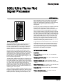
APPLICATION
The Honeywell 600U Ultra flame rod signal processor is a
reliable flame monitoring system based on the proven
principle of measuring rectified current flow through a flame
rod when a flame touches it. An AC voltage of 175 VAC is
applied to the flame rod; when a flame touches the rod, a
rectified current flows from the rod through the flame to the
ground of the burner. The 600U controller measures the
rectified current and energizes the flame relay if the current
exceeds the value for the flame-on setpoint. If the current flow
drops below the value for the flame-off setpoint, the flame
relay de-energizes. A visual display indicates whether or not
the flame relay is on and the relative signal strength, i.e., the
DC current flow through the flame.
The 600U is also capable of driving either (a) an ignition coil or
(b) an ignition transformer. (a) The ignition coil would be part
of an ignitor assembly; when using the ignition coil, the flame
rod which is used for sensing flame serves also as an ignition
rod. (b) AC power to an external ignition transformer is
switched on by a power relay in the 600U controller when an
ignition signal is applied. In this case, the high voltage from
the ignition transformer cannot be applied to the flame rod; a
separate ignition rod is required.
An AC or DC signal is applied to the 600U controller to turn on
the ignition coil and the ignition transformer. When the signal
is applied, the 600U controller pulses the ignition coil at 50 or
60 times per second, depending on the line frequency. The
ignition signal also causes a power relay in the controller to
close, connecting the controller’s AC input voltage (after
fuses) to an external ignition transformer if one is hooked up.
While the ignition signal is applied, the flame relay is
de-energized.
By means of a jumper the sensitivity of the 600U to flame can
be changed. Four sensitivity levels are provided. The
sensitivity of the display and the values of the flame-on and
flame-off setpoints are all changed together by the jumper.
Various protection features are provided. The flame rod itself
can be shorted to ground indefinitely without harm to the unit.
If the flame rod becomes fouled so that an unreasonably large
amount of AC current flows from the flame to ground, first a
yellow “ROD FOULED” LED is turned on. If the AC current
increases further a “ROD FAULT” LED is turned on and the
flame relay is de-energized. Note that the 600U controller
distinguishes between AC current flow due to fouling and DC
current flow caused by the presence of a flame.
If a grounded person touches the flame rod, he will receive a
perceptible shock, but he will not be hurt because less than
.5 mA of AC current will flow. If the flame rod is also being
used as an ignition rod and the rod is pulsed by an ignition
coil, the shock will be strong but it should not be dangerous
because of the short duration of the pulses.
SPECIFICATIONS
ELECTRICAL
Primary Input Power: 85 to 132 VAC, or 170 to 264 VAC;
50/60 Hz.
Input Current (monitoring only): 0.07 A at 115 VAC, 0.035 A
at 230 VAC.
Input Current (ignition on): 0.3 A at 115 VAC, 0.15 A at
230 VAC; plus current to ignition transformer (5 Amps max-
imum.)
Ignition Command Input: 12 to 50 VDC or 85 to 264 VAC, 50/
60 Hz.; (using labeled DC and AC inputs).
Command Current: 0.02 A DC at 50 VDC, 0.015 A RMS at
230 VAC.
Maximum Capacitance Load: 1.0 nF, flame rod drive to
ground (through wire insulation).

600U ULTRA FLAME ROD SIGNAL PROCESSOR
66-2070—01 2
OUTPUTS
Flame Relay: DPDT contacts, rated 5 A at 125 VAC,
277 VAC, and 30 VDC.
Ignition Transformer Relay: DPST contacts, rated 5 A at
125 VAC and 250 VAC.
Ignition Coil Drive: A capacitance of 4.4 μF is discharged
from 230 VDC through the ignition coil tap at the AC line
rate by a 4 A, 400 V SCR.
ENVIRONMENTAL
Ambient Temperature: Controller 0 to 60 °C (32 to 140 °F).
SAFETY
Flame rod voltage: 175 VAC at 115/230 VAC input.
Flame rod current (not firing):
Maximum current to ground <0.5 ma.
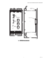
INSTALLATION
The 600U mounts on a 35 mm DIN rail. See Figure 1. The DIN
rail release is at the top of the unit.
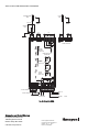
See Figure 2. Five Phoenix plugs are provided with the
controller, P1 through P5. AC power is connected to pins
AC L1 and AC L2 of P5. Set P4 for 115 VAC or 230 VAC
depending on the line voltage. The voltage does not have to
be extremely close to 115 VAC or 230 VAC; the controller is
quite tolerant accepting 85 VAC to 132 VAC or 170 VAC to
264 VAC. However, the flame signal strength will be affected
somewhat with AC voltage changes. This should not be a
problem because flame rods have excellent discrimination
between flame on and flame off.
The controller will operate equally well on 50 Hz or 60 Hz
power.
It is very important to connect the GND input on the controller
to the ground of the burner. It is assumed that the third wire
AC ground is at roughly the same potential as the burner
ground, so connection of GND to the AC line ground should
be satisfactory. If the GND input is left open, flame will not be
detected.
The ignition command is applied at pins IGN AC, IGN COM,
and IGN DC. A DC ignition command from 12 VDC to 50 VDC
is applied between IGN DC and IGN COM; it can be either
positive or negative in polarity. An AC ignition command from
85 VAC to 264 VAC (50 or 60 Hz) is applied between pins IGN
AC and IGN COM.
The 600U will operate equally well in several configurations:
flame rod only, flame rod with ignition coil, and flame rod with
ignition transformer. (It will also operate with both an ignition
coil and an ignition transformer.)
The connection for the flame rod only is shown in Figure 2; it
connects to the ROD/COIL pin on the controller. If the ignition
command is applied without the ignition coil present, the
voltage to the flame rod is not affected. The pulsing of the
ignition coil is done from the COIL TAP pin of the controller.
The connection of the ignition coil is shown in Figure 2. Pin C
for the coil is usually connected to ground in the ignitor
assembly; this ground connection is not necessary for coil
operation. The flame rod operates through the ignition coil
when the ignition coil is not being pulsed. When an ignition
command is present, with every pulse to the coil a strong
spark is emitted from the coil tip through the flame rod to
ground. The pulse rate will be the same as the line frequency,
50 or 60 pulses per second. The air gap between the flame
rod and ground should be 2 to 3 mm. The nominal arc voltage
is 7,000V. If the gap is very large, there will be no arc when the
coil is pulsed. Such pulsing will not be damaging to the coil.
The peak voltage at the coil tip when no arc results will not
exceed 11,000V.
When the ignition command is applied the AC power to an
ignition transformer is turned on by a DPST relay. See
Figure 2. The controller is shipped with two 5 A fuses
installed.
Front Panel Functions and Setup
Six numeric LED digits arranged vertically provide a graphic
visual display of the flame signal. If the Flame Rod is
connected and the AC power is on (green POWER LED will
be on) and there is no flame signal, none of the numeric digits
will be on. With a weak flame signal, either the “1” or “2” digits
will be on but the Flame Relay will be off. A stronger signal will
be indicated by “3” or a higher digit turning on; with this
stronger signal the Flame Relay will be turned on.
In normal operation when the flame is present the “5” or “6”
digits should be on with, perhaps, digit “4” turning on
occasionally. If the “3” or “4” digits are on most of the time, the
gain should be increased by moving P2 to a higher gain
position.
If the “6” digit is on steadily, the gain is probably set too high;
move the P2 plug to a lower gain position. If the LED for ROD
FOULED is on, the 600U controller will continue to operate,
but this is a warning that a small amount of AC current is
flowing from the flame rod to ground. This means that the
flame rod or its mount probably needs cleaning.
If the fouling gets to be significant, approach-ing the point
where the flame signal could be affected, the LED for ROD
FAULT will turn on, causing the flame relay to open. This fault
condition will be removed as soon as the fouling is sufficiently
reduced.

600U ULTRA FLAME ROD SIGNAL PROCESSOR
366-2070—01
Fig. 1. 600U Ultra flame rod controller.
3-1/4 (83)
5-31/64
(139)
35MM DIN RAIL
DIN RAIL
RELEASE
C
L
ROD
POWER
FAU LT
FLAME ROD
GOOD
SIG A
ROD
ROD
FOULED
GAIN 1
GAIN 2
NO JMPR = MAX GAIN 4
SIGNAL
RELAY ON
WEAK
SIGNAL
RELAY ON
POOR
SIGNAL
RELAY OFF
MODEL 600 ULTRA
GND
115 VAC 50/60 HZ
230 VAC 50/60 HZ
SIG B
ROD
XFMR
XFMR
AC
IGN
COM
IGN DC
IGN
RF ARF ARF ARF B
GAIN 3
RF B RF B
TURN IGN ON
TO XFMR LINE INPUT
SELECT FOR LINE INPUT
P1 P3
P4 P5
M33865
P2
9/32 (7)
2-63/64 (76)

600U ULTRA FLAME ROD SIGNAL PROCESSOR
Automation and Control Solutions
Honeywell International Inc.
1985 Douglas Drive North
Golden Valley, MN 55422
customer.honeywell.com
® U.S. Registered Trademark
© 2015 Honeywell International Inc.
66-2070—02 L.L. 03-15
Printed in United States
Fig. 2. Wiring the 600U.
ROD
FAULT
GOOD
TAP
COIL
ROD
FOULED
GAIN 1
GAIN 2
NO JMPR = MAX GAIN 4
SIGNAL
RELAY ON
WEAK
SIGNAL
RELAY ON
POOR
SIGNAL
RELAY OFF
MODEL 600 ULTRA
FLAME ROD
GND
115 VAC 50/60 HZ
230 VAC 50/60 HZ
COIL
ROD/
XFMRXFMR
AC
IGN COM
IGN DC
IGN
RF A RF A RF A RF B
GAIN 3 RF B RF B
TURN IGN ONTO XFMR LINE INPUT
SELECT FOR LINE INPUT
FLAME
ROD
IGNITION/FLAME
ROD
IGNITION
COIL
GAIN 1
GAIN 2
NO JMPR = MAX GAIN 4
GAIN 3
5A 5A
FLAME ROD ONLY
AC IN
GND
TO IGN XFMR
TAP
COIL COIL
ROD/
P1
P2 P3
P4
P5
GND
CBA
COIL TIP GND
GND
230 VAC POSITION
115 VAC POSIT ION
M33866
-
 1
1
-
 2
2
-
 3
3
-
 4
4


Honeywell 600U Ultra Flame Rod Signal Processor Operating instructions
- Type
- Operating instructions
Ask a question and I''ll find the answer in the document
Finding information in a document is now easier with AI
Related papers

Other documents
-
IRIS 600 Ultra Applications Manual
-
American Standard TUY Series Operating instructions
-
 Eclipse Combustion 5600 User manual
-
 Eclipse Combustion 5600 User manual
-
Amana GMH80603AN User manual
-
 GOODMAN GME80703BXC Series User manual
-
Eclipse 5600 No Purge Installation guide
-
Garland MCO-GS-10M User manual
-
Aerco Benchmark 5000 and 6000 User manual
-
Amana AMH* User manual


