Page is loading ...

Texmate,Inc.Tel.(760)598-9899•www.texmate.comDL-40-HZ manual (d0046) Page 1
• LineFrequencyinput.Easilyuserscaled.
• Threefrequencyrangesof99.99Hz,999.9Hzand9999Hz.
• Optionalisolated16bitanalogoutput.Userorfactoryscalable
to4to20mA,0to20mAor0to10Vacrossanydesired
digitalspanfrom±onecounttothefullscalerangeof0to
9999.
• Standardredoroptionalgreenorsuperbrightred4-digitLED
• Redorgreen0.8”LEDlargedisplayoption.
• FourannunciatorLEDsprovidefrontpanelalarmstatus
indicationforuptofoursetpoints.
• Optionalrelays.Two9AmpFormCandtwo4AmpFormA
relay,oroptionallyfour4AmpFormArelaysareavailable.
Input Specs:..............DependsonInputSignalConditioner
A/D Converter:..........14BitSingleSlope
Accuracy:..................±(0.05%ofreading+2counts)
Temp. Coeff.:.............100ppm/°C(Typical)
Warm up time:...........2minutes
Conversion Rate:......5conversionspersecond(Typical)
Display:......................4 digit 0.56" Red LED display (std),
0.56”Green,0.8"Red/Green,or
0.56"SuperBrightRedareoptional.
Range
0to9999counts.
Polarity:.....................Assumedpositive.Displays–negative
Decimal Selection:....AutomaticbyresolutionselectXXX•X
Positive Overrange:. . Topsegmentsofdigitaldisplayflash
Negative Overrange: Bottomsegmentsofdigitaldisplayflash
Relay Output:............Two4AmpFormArelaysandtwo9
AmpFormC,or4AmpformArelays.
Analog Output:.........Isolated16bituserscalablemAorV
AIC(mAout)...........
4-20mA@0to500Ωmaxloopresistance
AIV(voltsout).......... 0-10VDC@500Ωorhigherresistance
Power Supply:...........AC/DCAutosensingwiderangesupply
PS1 (std)................
85-265 VAC 50-400Hz / 95-300 VDC @ 3W
PS2.........................
15-48VAC50-400HZ/10-72VDC@2.5W
Operating Temp.:......0to50°C
Storage Temp:...........–20°Cto70°C.
Relative Humidity:....95%(noncondensing)
Case Dimensions:....11/8DIN,Bezel:96x48mm
(3.78”x1.89”)
Depthbehindbezel:117mm(4.61”)
Plus11.8mm(0.47”)forRight-angled
connectors,orplus20mm(0.79”)for
Straight-thruconnector.
Weight:.......................6.5oz.,8.5ozwhenpacked
CaseDimensions ............................... 8
ClearLockableWater-proofLensCoverOP-N4X/96X48
. . 9
ComponentLayout .............................. 8
ConnectorPinouts.............................. 7
ControlsandIndicators..........................2
DigitalRescaling................................ 4
DigitalRescalingProcedure.......................4
DigitalSpanSelectionforAnalogRangeOutput ....... 5
GeneralFeatures ............................... 1
GlossaryofProgrammingSymbols.................2
MetalSurroundCaseOP-MTL96X48...............9
OrderingInformation...........................10
PinDescriptions ................................ 7
Range,DecimalPoint&BrightnessSelection .................5
SetpointSetting&RelayConfigurationMode
.............. 6
SoftwareFeatures.............................. 1
SoftwareLogicTree .............................3
Specifications ..................................1
TwoPointAnalogOutputRangeSetting&Calibration. . 5
AC Frequency Meter Controller and Transmitter
with ranges of 0.01Hz, 0.1Hz and 1Hz
General Features Specifications
Software Features
Index
• Three-buttonprogrammingfromthefrontpanel
(UP,DOWNandPROGRAMbuttons).
• Threefrontpanelselectableranges.
• Frontpanelselectable
four-levelbrightnesscontrolofdigitaldis-
play,andsetpointLEDs
.
•
Fourprogrammablesetpoints.
• Relayactivationcanbeselectedtooccurabove(HI)orbelow
(LO)eachsetpoint.
• Hysteresissettingforallfoursetpoints.Delayonmakeand
delayonbreakforSP1andSP2.
• PeakandValley.ViewandReset.
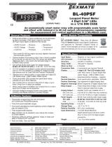
LEOPARD FAMILY
DL-40-HZ
Leopard Line Frequency Meter
4 Digit 0.56” LEDs
in a 1/8 DIN CASE

Texmate,Inc.Tel.(760)598-9899•www.texmate.comPage2 DL-40-HZ manual (d0046)
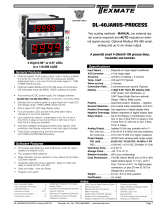
Front Panel Buttons
Program Button
The
P
button isusedtomovefromoneprogramsteptothe
next.Whenpressedatthesametimeasthe button,itiniti-
atesthecalibration mode.Whenpressedatthesametimeas
the button,itinitiatesthesetpoint setting mode.
Up Button
When in the operational display, pressing the button alone
allowsyoutoview,butnotchange,thesettingofsetpoint 1.
Wheninthecalibration modeorthesetpoint setting modethe
buttonisusedtoincreasethevalueofthedisplayedparame
ter.
Down Button
When in the operational display, pressing the button alone
allowsyoutoview,butnotchange,thesettingofsetpoint 2.
Wheninthecalibration modeorthesetpoint setting modethe
buttonisusedtodecreasethevalueofthedisplayedparameter.
UPARROW
BUTTON
DOWNARROW
BUTTON
Setpoint
Annunciator
LEDs Program
lockout
header
behind
faceplate.
SP4
SP3
SP2
SP1
PROGRAM
BUTTON P
SetpointAnnunciatorLEDs
SP1SP2SP3SP4
Program
lockout
header
behind
faceplate.
Symbol Explanation
This symbol represents the
OPERATIONALDISPLAY.
ThisisthePROGRAMbutton.
ThisistheUPbutton.
ThisistheDOWNbutton.
When a button is shown, press and
releaseitto go onto the nextstepin the
direction indicated by the arrow. When
an alternative dotted line is shown, this
indicates that an alternative logic branch
will be followed when a particular option
ispresent.
When two buttons are shown side by
side and enclosed by a dotted line, they
must be pressed at the same time then
releasedtogoontothenextprogramming
step.
IfthedisplayisshownwithXXXXitmeans
thevaluedisplayedwillbethepreviouslyset
value.Whenanumberisshownitindicates
theinitialfactorydefaultsettingoraspecific
“examplenumber”.
P
P
Whentwodisplaysareshowntogetherwith
bursts, this indicates that the display is
toggling(flashing)betweenthenameofthe
functionandthevalue.
Text or numbers shown between square
brackets in a procedure indicate the pro-
grammingcodenameofthefunctionorthe
valuedisplayedonthemeterdisplay.
When the
and
buttons are shown
together,thedisplayvaluecanbeincreased
by pressing and releasing the
button
ordecreasedbypressingandreleasingthe
button.
When the
and
buttons are shown
with two displays, either display can be
selectedbypressingandreleasingthe
or
buttons.
Whentherearemorethantwodisplayselec-
tions they are shown in brackets below the
firstdisplayandarealsoselectablebypress-
ingandreleasingthe
or
buttons.
A dotted box indicates these functions are
omittedorbypassedwhentherelatedhard-
wareisnotpresent
Toexplainsoftwareprogrammingprocedures,logicdiagrams
areusedtovisuallyassistinfollowingtheprogrammingsteps.
Thefol-lowingsymbolsareusedthroughoutthelogicdiagrams
torepresentthebuttonsandindicatorsonthemeter:
[ScLE]
[9999]
Offset
Glossary of Programming Symbols
Controls and Indicators
P
[X•XXX]
[XX•XX]
[XXX•X]
[XXXX•]
[XXXX]

Texmate,Inc.Tel.(760)598-9899•www.texmate.comDL-40-HZ manual (d0046) Page3
SETPOINT SETTING AND
RELAY CONFIGURATION MODE
See Page 6
Set Setpoint 1
[SP1]
Delay-on-Make
[doM]
Delay-on-Break
[dob]
Setpoint 2
[SP2]
Hysteresis
[hYSt]
Hysteresis
[hYSt]
Hysteresis
[hYSt]
Hysteresis
[hYSt]
Delay-on-Make
[doM]
Delay-on-Break
[dob]
Setpoint 3
[SP3]
NOTE: [dob] [dom] Functions
are only available for
SP1 and SP2
Setpoint 4
[SP4]
Relays Activation [rLYS]
[H] High, the relay energizes
when the setpoint is exceeded.
[L] Low, the relay
energizes below the setpoint.
Setpoint are indicated from left
to right SP1, SP2, SP3, SP4
Peak
[PEAK]
Reset
PEAK
Reset
VALY
Setpoint 1
[SP1]
Setpoint 2
[SP2]
[LhLh]
[hLhL]
[hhhh]
MAIN MENU
Operational Display
SETPOINT
VIEW ONLY MODE
PEAK & VALLEY
VIEW & RESET
Sub-menu
MODE
Calibration
Mode
Calibration
Mode
RANGE, DECIMAL POINT AND
BRIGHTNESS SELECTION
See Page 4
Setpoint 3
[SP3]
Setpoint 4
[SP4]
Valley
[VALY]
Offset
[oFFS]
Scale Factor
[ScLE]
Range
[rG]
[X•XXX]
[XX•XX]
[XXX•X]
[XXXX•]
[XXXX]
[99•99]
[9999]
[999•9]
[2]
[3]
[4]
Decimal Point
[dp]
Display Brightness
[br]
Analog High
[Anhi]
Analog Low
[AnLo]
TWO POINT ANALOG OUTPUT
RANGE SETTING AND
CALIBRATION
See Page 5
DIGITAL
RESCALING MODE
See Page 4
DIGITAL SPAN
SELECTION FOR ANALOG
RANGE OUTPUT
See Page 5
This branch will only appear
if the analog output option
is installed
Select the Digital Value
at which the Analog Output
Hi [chi] Range will occur
Select one of three
Ranges: 99.99Hz,
999.9Hz or 9999Hz
Default is 9999
for Direct Reading
of Frequency
Select the Digital Value
at which the Analog Output
Lo [cLo] Range will occur
Goes directly
to Zero setting
if Analog Output
is not installed
Calibrate Analog
Output Low
[cLo]
Calibrate Analog
Output High
[chi]
+
–
4.00
+
–
20.00
Set the Decimal Point
1 Dimmest
2 Dim
3 Bright
4 Brightest
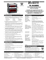
The DL-40F is an intelligent meter with a hierarchical
software structure designed for easy programming and
operation,asshownbelowinthesoftwarelogictree.
After the meter has been powered up, the four
digitslightupforthreesecondsandthensettleto
theoperationaldisplayindicatingtheinputsignal.
15 Second Program Timeout
Themeterhasa15secondprogramtimeout.If
nobuttonsarepressedfor15seconds,atany
stageoftheprogrammingsequencethemeter
will exit the programming mode and return to
the operational display.Any program changes
thatweremadepriortopressingthe
P
button
intheprecedingstepwillnotbesaved.
Software Logic Tree for DL-40F Leopard Frequency Meter

Texmate,Inc.Tel.(760)598-9899•www.texmate.comPage4 DL-40-HZ manual (d0046)
ThisFrequencymetermayberescaledwithoutthenecessityofapplyinganexternalsignalbychangingtheOffsetandScalefactor.
Offsetisthereadingthatthemeterwilldisplayforazeroinput.TheOffsetmaybesettoanyvaluefrom-1999to+9999.The
defaultvalueoftheOffsetis000.
Scalefactoristhedigitalgainofthemeter.ThedisplayedreadingisdirectlyproportionaltotheScalefactor.Thedefaultvalueof
thescalefactoris9999,fordirectfrequencymeasurement,butitmaybesettoanyvaluebetween-1999and+9999forreading
anydesiredengineeringunit.
MAIN MENU
Operational Display
Sub-menu
MODE
STEP A
Calibration Mode
[cAL]
STEP B
Calibration Mode
[cAL]
DECIMAL POINT AND
BRIGHTNESS SELECTION
See Page 5
STEP C
Offset
[oFFS]
STEP D
Scale Factor
[ScAL]
TWO POINT ANALOG
OUTPUT RANGE SETTING
AND CALIBRATION
See Page 5
RANGE, DECIMAL POINT &
BRIGHTNESS SELECTION
STEP E
Range
[rG]
[2]
[3]
[4]
STEP G
Display Brightness
[br]
[X•XXX]
[XX•XX]
[XXX•X]
[XXXX•]
[XXXX]
STEP F
Decimal Point
[dp]
[99•99]
[9999]
[999•9]
DIGITAL SPAN SELECTION
FOR ANALOG RANGE OUTPUT
See Page 5
STEP A Enter the Calibration Mode
1) Pressthe
P
and buttonsatthesametime.
Displaytogglesbetween[cAL]and[oFF].
2) Pressthe or button.
Displaychangesfrom[oFF]to[on].
3) Pressthe
P
button.Displaytogglesbetween[cAL]and[out].
STEP B Select Between Calibration of Input or Output
Note:Iftheanalogoutputoptionisnotpresent,StepBisskippedandthe
programgoesdirectlyfromStepAtoStepC.
1) Pressthe or buttontoselectthedisplaytogglingfrom[cAL]
to[iP].
2) Pressthe
P
button.Displaytogglesbetween[oFFS]andthe
previousoffsetsetting.
STEP C Set the Offset
1) Pressthe
P
button.Displaytogglesbetween[oFFS]andthe
previousoffsetsetting.Fordirectfrequencymeasurement,setthe
offsetto0.
Ifadisplaythatisscaledtoreadinengineeringunitsisrequired,
thisoffsetmaybesettoanyvaluefrom-1999to+9999.
2) Pressthe
P
button.Displaytogglesbetween[rG]andthe
previoussetting.(Seepage5forsettingrange,decimalpointand
brightness)
STEP D Set the Scale Factor
1) Pressthe or button.Displaychangesfrom[out]to[iP].
2) Pressthe
P
button.Displaytogglesbetween[ScLE]andthe
previousscalesetting.
3) Fordirectfrequencymeasurement,setthescaleto9999.
Ifadisplaythatisscaledtoreadinengineeringunitsisrequired,
thisscalefactormaybesettoanyvaluefrom0to9999.
The Digital Rescaling Procedure Mode is Now Complete.
ThemenubranchestotheRANGE,DECIMALPOINTANDBRIGHTN
ESSSELECTION.
Digital Rescaling
Digital Rescaling Procedure
STEP E Select the Range
1) Usingthe and buttons,selecttherequiredrange.Thereare
threerangesof99.99Hz,999.9Hzand9999Hz
2)
Pressthe
P
button.Displayshowstheprevious[dp]decimalpoint
selection.
STEP F Select the Decimal Point
1) Usingthe and buttons,adjustthedisplaytothedesired
decimalpointsetting.
2) Pressthe
P
button.Displaytogglesbetween[br]andtheprevious
brightnesssetting.
STEP G Set the Display Brightness
1) Usingthe and buttons,adjustthedisplaytothedesired
brightnesssetting(4isthebrightestsetting).
2) Pressthe
P
button.Displaybrightnesschangestonewsettingand
displaytogglesbetween[Anhi]andtheprevious[Anhi]setting.
Range, Decimal Point and Brightness Selection

Texmate,Inc.Tel.(760)598-9899•www.texmate.comDL-40-HZ manual (d0046) Page5
STEP A Enter the Range, Decimal Point and Brightness Mode Through the Sub
Menu [CAL] [oFF]
1) Pressthe
P
and buttonsatthesametime.
Displaytogglesbetween[cAL]and[oFF].
2) Pressthe
P
button.Displayshowsprevious[rG]selection.
3) Pressthe
P
button3timestoentertheDigitalSpanSectionforAnalog
RangeOutput.
Note:FordetailsonselectingRange,DecimalPointandBrightnessseepage4.
Two Point Analog Output Range Setting and Calibration
Range, Decimal Point and Brightness Selection
Digital Span Selection for Analog Range Output
MAIN MENU
Operational Display
Sub-menu
MODE
STEP A
Calibration Mode
[cAL]
DIGITAL
RESCALING
MODE
See Page 4
TWO POINT ANALOG OUTPUT
RANGE SETTING & CALIBRATION
See Page 5
STEP B
Calibration Mode
[cAL]
STEP C
Calibrate Analog
Output Lo
[cLo]
STEP D
Calibrate Analog
Output Hi
[chi]
[X•XXX]
[XX•XX]
[XXX•X]
[XXXX•]
[XXXX]
[2]
[3]
[4]
Decimal Point
[dp]
Display Brightness
[br]
STEP G
Analog High
[Anhi]
STEP H
Analog Low
[AnLo]
DIGITAL SPAN SELECTION
FOR ANALOG RANGE OUTPUT
RANGE, DECIMAL POINT AND
BRIGHTNESS SELECTION
STEP A
Range
[rG]
[99•99]
[9999]
[999•9]
STEP E Selecting the [Anhi] Digital Value for Analog High Output
1) Using the and buttons, adjust the display to the desired digital value at
which the [chi] Calibrated Analog High output will occur. For digital readings
outside the digital span selected, the analog output will linearly rise above the
value set for chi, up to the maximum analog output capability. However, the
analogoutputwillnotgolowerthanthecalibratedvaluesetforcLo(seebelow).
2) Pressthe
P
button.Displaytogglesbetween[AnLo]andprevious[AnLo]setting.
STEP F Selecting the [AnLo] Digital Value for Analog Low Output
1) Usingthe and buttons,adjustthedisplaytothedesireddigitalvalueat
whichthe[cLo]CalibratedAnalogLowoutputwilloccur.
ForDigitalreadings
outside the Digital Span selected, the analog output will not go lower than the
calibratedvaluesetforcLo
.
2) Pressthe
P
button.
Thedisplaytogglesbetween[cto]and[oFF].
Note:Anytwodigitalspanpointsfrom–1999to9999canbeselected.Thedigitalvaluesfor[Anhi]
analoghighand[AnLo]analoglowcanbereversedtoprovidea20to4mAoutput.Thedigitalspan
selectedcanbeassmallastwocounts,whenusingtheanalogoutputtofunctionasaControlor
AlarmDriver.Smalldigitalspanswillcausethehighresolution16bitDtoAtoincrementdigitallyin
staircasesteps.
STEP A Enter the Calibration Mode
1) Pressthe
P
and buttonsatthesametime.
Displaytogglesbetween[cAL]and[oFF].
2) Pressthe or button.Displaychangesfrom[oFF]to[on].
3)
Pressthe
P
button.Displaytogglesbetween[cAL]and[out]inputcalibration.
Note:Ifatthispointthedisplayskipsdirectlytotogglebetween[oFFS]andtheprevious[oFFS]
setting,thesoftwareisdetectingthattheoptionalanalogoutputhardwareisNOTinstalled.
STEP B Enter the Analog [oUT] Output Mode
1)
Pressthe
P
button.Displaytogglesbetween[cLo]andaninternalscalefactor.
STEP C Set or Calibrate the [cLo] Low Analog Output Range
1) Selectthevoltageorcurrentloopoutputheaderpositionontheoutput
module.(SeeComponentLayoutonpage9).
2) Connectamultimetertopins16and17ontheoutputmodule.(SeeRear
PanelPinoutsonpage8).Usingthe and buttons,adjusttheanalog
outputtothedesiredlowvalueasshownonthemultimeterdisplay.
cLomaybeadjustedtoanyvaluefrom–0.3mAto17mA(mAoutput
selected)orfrom–0.6Vto8V(voltoutputselected)
3)
Pressthe
P
button.Displaytogglesbetween[cHi]andaninternalscalefactor.
STEP D Set or Calibrate the [cHi] High Analog Output Range
1) Usingthe and buttons,adjusttheanalogoutputtothedesiredhigh
valueasshownonthemultimeterdisplay.cHimaybeadjustedtoanyvalue
from17mAto21mA(mAoutputselected)orfrom8Vto10.3V(volt
output selected).However,thevaluemustbehigherthanthevalueselectedfor
cLo.
2) Pressthe
P
button.Thedisplayexitsthecalibrationmodeandreturnsto
theoperationaldisplay.
Note:HavingestablishedtheLowandHighrangeoftheanalogoutput,thetwodigital
pointsbetweenwhichtheanalogoutputwilloccurcannowbeselected.(SeeDigitalSpan
Selectionbelow).

Texmate,Inc.Tel.(760)598-9899•www.texmate.comPage6 DL-40-HZ manual (d0046)
SETPOINT SETTING AND
RELAY CONFIGURATION MODE
See Page 6
STEP B
Set Setpoint 1
[SP1]
STEP C
Delay on Make
[doM]
STEP D
Delay on Break
[dob]
STEP F
Setpoint 2
[SP2]
STEP E
Hysteresis
[hYSt]
STEP I
Hysteresis
[hYSt]
STEP K
Hysteresis
[hYSt]
STEP M
Hysteresis
[hYSt]
STEP N
Relays Activation
[rLYS]
STEP G
Delay on Make
[doM]
STEP H
Delay on Break
[dob]
STEP J
Setpoint 3
[SP3]
NO
TE: [dob] [doM]
Functions are
only available for
SP1 and SP2
STEP L
Setpoint 4
[SP4]
[LhLh]
[hLhL]
[hhhh]
MAIN MENU
Operational Display
STEP A
Thefollowingprogrammingstepsarerequiredtoenterthesetpointvaluesandconfiguretherelay
functionsinameterwithfourrelaysusingfoursetpoints.Generallyiflessthanfourrelaysare
installedthesoftwareautodetectsmissingrelaysanddeletesreferencetothemfromthemenu.In
somecasessetpointswithoutrelaysareoperationalfordisplayonlypurposes.
STEP A Enter the Setpoint Mode
1) Pressthe
P
and buttonsatthesametime.
Displaytogglesbetween[SP1]andtheprevious[SP1]setting.
STEP B Set Setpoint 1 (SP1)
1) Usingthe and buttons,adjustthedisplaytothedesiredSP1value.
2) Pressthe
P
button.Displaytogglesbetween[doM]andtheprevious[doM]setting.
STEP C Set the SP1 Delay-on-Make (doM) Delay Time Setting
1) Usingthe and buttons,adjustthedisplaytothedesired[doM]value
(0to9999seconds).Thereadingmustcontinuouslyremaininanalarmcondition
untilthisdelaytimehaselapsedbeforetherelaywillmakecontact(energize).
2) Pressthe
P
button.Displaytogglesbetween[dob]andtheprevious[dob]setting.
STEP D Set the SP1 Delay-on-Break (dob) Delay Time Setting
1) Usingthe and buttons,adjustthedisplaytothedesired[dob]value(0to9999
seconds).Thereadingmustcontinuouslyremaininannon-alarmconditionuntilthis
delaytimehaselapsedbeforetherelaywillbreakcontact(de-energize).
2) Pressthe
P
button.Displaytogglesbetween
[hYSt]
andtheprevious
[hYSt]
setting.
STEP E Set the Hysteresis Setting for Setpoint 1
1)
Usingthe and buttons,adjustthedisplaytothedesiredhysteresis[hYSt]value.
2) Pressthe
P
button.Displaytogglesbetween[SP2]andtheprevious[SP2]setting.
NOTE:HalfoftheHysteresisvalueselectedisappliedaboveandbelowthesetpoint.
NOTE: Steps F, G, H and J have functionally the same procedure as steps B, C, D, and E shown above.
STEP F Set Setpoint 2 (SP2)
STEP G Set the SP2 Delay-on-Make (doM) Delay Time Setting
STEP H Set the SP2 Delay-on-Break (dob) Delay Time Setting
STEP I Set the Hysteresis Setting for Setpoint 2
1)
Usingthe and buttons,adjustthedisplaytothedesiredhysteresis[hYSt]value.
2) Pressthe
P
button.Displaytogglesbetween[SP3]andtheprevious[SP4]setting.
STEP J Set Setpoint 3 (SP3) (No[doM]or[dob])
1) Usingthe and buttons,adjustthedisplaytothedesiredSP3value.
2) Pressthe
P
button.Displaytogglesbetween
[hYSt]
andtheprevious
[hYSt]
setting.
STEP K Set the Hysteresis Setting for Setpoint 3
1)
Usingthe and buttons,adjustthedisplaytothedesiredhysteresis[hYSt]value.
2) Pressthe
P
button.Displaytogglesbetween[SP4]andtheprevious[SP4]setting.
STEP L Set Setpoint 4 (SP4) (No[doM]or[dob])
1) Usingthe and buttons,adjustthedisplaytothedesiredSP4value.
2) Pressthe
P
button.Displaytogglesbetween[hYSt]and0.
STEP M Set the Hysteresis Setting for Setpoint 4
1)
Usingthe and buttons,adjustthedisplaytothedesiredhysteresis[hYSt]value.
2) Pressthe
P
button.Displaytogglesbetween[rLYS]andthepreviousrelaysetting.
STEP N Set Relay Activation mode [rLYS]
(h)Hightherelayenergizeswhenthesetpointisexceeded.(L)Lowtherelayenergizes
belowthesetpoint.ThesetpointisindicatedfromlefttorightSP1,SP2,SP3,SP4.
1) Usingthe and buttons,adjustthereadingonthedisplaytothedesired
relaysettings:[LLLL],[LhLh],[hLhL],[hhhh].
Ifonly2relaysinstalled[Lh][hL][hh][LL].
2) Pressthe
P
button.
Themeterexitsthesetpointmodeandreturnstotheoperationaldisplay.
The Setpoint Relay programming mode is now complete.
Setpoint Setting and Relay Configuration Mode

Texmate,Inc.Tel.(760)598-9899•www.texmate.comDL-40-HZ manual (d0046) Page7
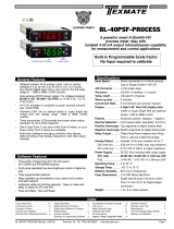
Connector Pinouts
Pin Descriptions
Pin Descriptions (continued)
Input Signal – Pins 1 to 3
Pin 1 to 3 Input
Pins 8 to 12 – Relay Output Pins
Note:Ifrelaysforsetpoints1&2areinstalledonthe
mainboard,andarelayoutputmoduleisusedthatalso
hasrelaysinthesetpoints1&2positions,theduplicate
relayswilloperateinunison.
Pin 8 SP1 NO. NormallyOpen4AmpFormA.
Pin 9 SP1 NO.
Pin 10 SP2 NO. NormallyOpen4AmpFormA.
Pin 11 SP2 NO.
Pin 12 NO CONNECTION.
Pins 14 and 15 – AC/DC Power Input
Auto-sensingAC/DCpowersupply.Forvoltagesbetween
85-265VAC/95-300VDC(PS1)or18-48VAC/10-72VDC(PS2).
Pin 14 AC/DC Neutral.Neutralpowersupplyline.
Pin 15 AC/DC line.Livepowersupplyline.
Optional Carrier Board Output Pins
Pins 16 and 17 – Analog Output
Pins16and17aretheanalogoutputpinsontheoptional
outputmodule.Theirpindefinitionsare:
Pin 16 Positive(+)analogoutput.
Pin 17Negative(–)analogoutput.
Pins 18 to 21 – Rear Panel Function Pins
Pins 18 to 21providefunctionsthatcanbeimplemented
withanexternalswitch.Theirpindefinitionsare:
Pin 18 DIM.Byconnectingthedisplaydim(DIM)pinto
theCOMMONpin,thedisplaybrightnesssetting
ishalved.
Pin 19 COMMON.ToactivatetheLOCKorDIM
functionsfromtherearofthemeter,the
respectivepinshavetobeconnectedtothe
COMMONpin.Thispinisconnectedtothe
internalpowersupplyground.
Pins 22 to 29 – Output Module Pins
!
WARNING: AC and DC input signals and power
supply voltages can be hazardous. Do Not connect live
wires to screw terminal plugs, and do not insert, remove
or handle screw terminal plugs with live wires connected.
17 16
14 158910 11 12
See Leopard Family Input
Signal Conditioning Modules
123456
21 20 19 18
Relay Outputs
SP1
NO
SP1
NO
SP2
NO
SP2
NO
LOCK
HOLD
COMMON
DIM
ANALOG
OUTPUT –
AC
Neutral
– DC
AC
Line
+ DC
ANALOG
OUTPUT
+
29 28 27 26 25 24 23 22
Pinout Diagram
TheRearViewoftheMeterdiagramshowsthemeterwiththe
relayconfiguration:dual9AmpFormCanddual4AmpForm
Arelays.Ananalogoutputmoduleisalsoshownasinstalled.
TheDL-40-ACA/DL-40-ACVuseplug-intypescrewterminalcon-
nectors for all input and output connections. The power supply
connections(pins14and15)haveauniqueplugandsocketout-
linetopreventcrossconnection.Themainboardandinputsignal
conditioner use right-angled connectors as standard. The output
moduleusesstraight-thruconnectorsasstandard.
Auto-sensingAC/DCpowersupply.Forvoltagesbetween
85-265VAC/95-300VDC(PS1)or18-48VAC/10-72VDC(PS2).
29 28 27 2526 24 23 22
DL Series
Options
4A
4A
Order Code
OR11
OR12
OR23
OR14
-
-
-
-
-
-
-
4A
4A
4A
4A
10A -
-
OR15
OR16
SP2 SP4 SP1 SP3
9A
9A
9A
9A
9A
9A
9A
9A
SP3SP1SP4SP2
Relay Modules with 2 Non-Isolated 4A Form A Relays,
and 2 Non-Isolated 9A Form C Relays
29 28 27 2526 24 23 22
DL Series
OptionsOrder Code
OR54 210mA210mA210mA210mA
SP4 SP3 SP2 SP1
SP4 SP3 SP2 SP1
Relay Modules with 4 Independent 300V
(210mA DC only)
29 28 27 2526 24 23 22
DL Series
OptionsOrder Code
OR31
OR32
OR33
OR34
-
-
-
- -
-
5A5A 5A 5A
5A 5A
5A
5A
5A
5A
SP4 SP3 SP2 SP1
SP1SP2SP3SP4
Relay Modules with 4 Isolated 5A Form A Relays
Pin 20 HOLD.ByconnectingtheHOLDpintothe
COMMONpin,thedisplayedreadingisfrozen,
however,A/Dconversionscontinue.Whenthe
HOLDpinisdisconnectedfromtheCOMMON
pin,thecorrectreadingisdisplayed.
Pin 21 LOCK. ByconnectingtheLOCKpintothe
COMMONpin,themeter'sprogrammed
parameterscanbeviewedbutnotchanged.

Texmate,Inc.Tel.(760)598-9899•www.texmate.comPage8 DL-40-HZ manual (d0046)
96 mm
(3.78")
48 mm
(1.89")
3.9 mm
(0.15") typical
FRONT VIEW
1/8 DIN 96x48mm
These dimensions are
increased by 1.6mm (0.06")
when the metal surround
case is installed.
The 96x48mm case is
particularly suitable for
mounting in mosaic panels
or insulative panels up to 2"
thick. They can also stack
mount, 2 up in existing
cutouts for 1/4 DIN
(96x96mm) or 4 up in
1/2 DIN (96X192mm).
NOTE: The Metal Surround Case
is pre-installed at the factory and cannot
be removed without damage to the case.
Metal Surround Case
P/N:(OP-MTL96X48)
uses
Metal Screw Mount Clips
and has a max. panel
thickness mounting
of 15.5 mm (0.61").
Removable
Key-lock
Cam
Opening
Safety
Catch
Clear Lockable NEMA 4X
Splash Proof Cover
P/N:(OP-N4/96x48)
40.8 mm
(1.61")
117 mm
(4.61")
SIDE VIEW
5.3 mm
(0.21")
3.7mm
(0.15")
43.4 mm
(1.71")
DIN Cutout spacers
Straight-thru Connector for
meters with output board
20mm (0.79")
Right-angled Connector
11.8mm (0.47")
PANEL CUTOUT
Case will mount in standard 1/8 DIN cutouts
45 mm
(1.77")
Snug Fitting
Mosaic Fitting
92 mm
(3.62")
Loose Fitting
91.6mm
(3.6")
40.8mm
(1.61")
8 places
3mm
(0.12")
8 places
4mm
(0.16") 43.4mm
(1.71")
1/8 DIN
Cutout spacers
87.4mm
(3.45")
Various bezel
colors are available.
Black is standard.
Prog.
SP3
SP4
SP2
SP1
For additional strength, extra Mounting
Slide Clips can be ordered and doubled up
one behind the other. P/N: (75-DMTCLIPF)
TOP VIEW
87.4mm
(3.45")
mosaic
fitting
95.4mm
(3.77")
Max. panel thickness
50mm
(1.97")
96 mm
(3.78")
91.6mm
(3.6")
DIN
Cutout
Spacer
To open rear cover,
use a small flat
bladescrew driver.
Press down lightly to
release catch on top
or bottom of case
and leaver outwards.
4.7mm
(0.19")
DIN Cutout Spacer
2mm
(0.08")
Connector
Socket
Prog. SP1
SP1 SP2 SP4SP3 SP5 SP6
Prog. SP1
SP1 SP2 SP4SP3 SP5 SP6
Prog. SP1
SP1SP2 SP4SP3 SP5 SP6
When extra panel
mounting tightness is
required, order the
optional screw mount clip.
P/N:(OP-MTLCLIP)
High Strength Panel
Mounting Kit
P/N: OP-PMA96X48
For extra strength in portable applications, the 8 DIN
spacers should be snipped off and the Mosaic fitting
cutout used. Alternatively, the High Strength Panel
Mounting Kit (Part # OP-PMA96X48) can be used.
Panel adaptor plates are
available to retrofit most
existing panel cutouts.
Case Dimensions
Component Layout
MAIN BOARD
MAIN BOARD HI BOLTAGE MAIN BOARD LOW BOLTAGE
INPUT LO
INPUT HI
60 to 500V AC
High Accuracy Digital
Frequency Measurement
IF08:
Line Frequency
Line Frequency 99.99/999.9/9999Hz
Input Module IF08

Texmate,Inc.Tel.(760)598-9899•www.texmate.comDL-40-HZ manual (d0046) Page9
Clear Lockable Water-proof Lens Cover OP-N4X/96X48
Metal Surround Case Option OP-MTL96X48
The clear lockable cover is designed to be dust
and water proof to NEMA-4X, IP65 standards. The
assembly consists of a base and cover with a cam
hingeand key-lock fasteningmechanism.AnO-ring,
or neoprene gasket forms a seal between the base
andthepanel.Thecamhingepreventsthecoverfrom
closingwhenopeneduntilpushedclosed.Thecover
hasataperedrecessthat,whenclosed,formsaseal
withataperedspigotonthebase.Akey-lockemploys
a cam locking device to force the spigot into the
recess, ensuring seal integrity.A safety catch keeps
thecoverclosedevenwhenthekeyisremoved,and
thekeyholecanbeusedtoattachasafetysealclip,
preventingunauthorizedopening.
The meter’s plastic case is made from fire retardant polycar-
bonate.Ametalsurroundcasecanbeorderedtoenhancethe
meter’s fire retardant capabilities and also provide shielding
against electromagnetic interference (EMI). The metal case
slidesoverthepolycarbonatecaseandisheldfirmlyinplaceby
spring-typenon-returnclips.TheMetalSurroundCasemustbe
factoryinstalledonthepolycarbonatecaseandonceinstalled,
itcannotberemovedinthefield.
Ground
Tab
Metal Surround Case
& Mounting Clips
Part No.
OP-MTL96X48
Meter with Metal
Surround Case
and screw-type mounting clips
assembled
Screw-type
Mounting Clip
Withthemetalcaseinplace,themeter’sstandardratchet-type
mountingclipscan not be used. Instead apairofscrew-type
DINstandardmountingclipsareprovided,whichclipintoholes
onthesideofthemetalcaseandtightenagainsttherearofthe
panel.Agroundtabonthemetalcaseenablesthemetalcase
tobeeasilyconnectedtothepanelground.
Installation Guidelines
Installation
1.Installandwiremeterperlocalapplicablecodes/reg-
ulations,theparticularapplication,andgoodinstallation
practices.
2.Installmeter ina locationthatdoes notexceed the
maximum operating temperature and that provides
goodaircirculation.
3. Separate input/output leads from power lines to
protect the meter from external noise. Input/output
leads should be routed as far away as possible from
contactors,controlrelays,transformersandothernoisy
components.Shieldingcablesforinput/outputleadsis
recommended with shield connection to earth ground
nearthemeterpreferred.
4.Acircuitbreakerordisconnectswitchisrequiredtodis-
connectpowertothemeter.Thebreaker/switchshouldbe
incloseproximitytothemeterandmarkedasthediscon-
nectingdeviceforthe meterormetercircuit.Thecircuit
breakerorwallswitchmustberatedfortheappliedvoltage
(e.g.,120VACor240VAC)andcurrentappropriateforthe
electricalapplication(e.g.,15Aor20A).
5.SeeCase Dimensions sectionforpanelcut-
outinformation.
6.SeeConnector Pinouts sectionforwiring.
7.Use28-12AWGwiring,minimum90˚C(HH)
temperaturerating. Strip wire approximately 0.3in. (7-8
mm).
8.Recommendedtorqueonallterminalplugscrewsis4.5
lb-in(0.51N-m).
!

Texmate,Inc.Tel.(760)598-9899•www.texmate.comPage10 DL-40-HZ manual (d0046)
BASIC MODEL NUMBER
DL-40-HZ ... 96x48mm, Leopard, 4 Digit, Line Frequency ............ $110
Standard Options for this Model Number
Order Code Suffix Description List
DISPLAY
DR.....Red LED, 0.56 inch high .............................N/C
DB....Super–brightRedLED,0.56inchhigh...............$25
DG...GreenLED,0.56inchhigh.........................$10
LG....LargeGreenLED,0.8inchhigh....................$45
LR....LargeRedLED,0.8inchhigh......................$35
POWER SUPPLY
PS1 ....85 - 265VAC / 95 - 300VDC................................N/C
PS2...15-48VAC/10-72VDC...........................$35
INPUT MODULES
(Partial List. See www.texmate.com)
UnlessotherwisespecifiedTexmatewillshipallmodulesprecalibrated
withfactorypreselectedrangesand/orscalingsasshowninBOLDtype.
IF08..LineFrequency99.99/999.9/9999Hz.................$45
ANALOG OUTPUT*Add$7foranOutputModuleCarrierBoard
AIC..
Isolated16BitCurrentOutput,0-20mAand4-20mA,pls.specify
$
35
AIV. . Isolated16BitVoltageOutput,0-10VDC...........
$
35
RELAY OUTPUT
Note:R1andR2arelocatedonthemainboard,andaregeneral-
lyusedwhenonlytwoFormARelaysorlessarerequiredandan
AnalogyOutputisnotrequired.
R1... Single4AFormARelay.........................
$
30
R2... Dual4AFormARelays .........................
$
55
RELAY OUTPUT MODULES
Note: IfameterisorderedwithaRelayOutputModule,butwithout
AnalogOutput,anOutputModuleCarrierBoardshouldbeautomatical-
lyaddedtotheorder.
OR11..One9AmpFormCRelay,Isolated .........................$30
OR15..One9AmpFormCandTwo4AmpsFormARelays ...........$75
OR16..One9AmpFormCandOne4AmpFormARelays............$55
OR12..Two9AmpFormCRelays,Isolated ........................$60
OR14..Two9AmpFormCandTwo4AmpsFormARelays ...........$105
OR23..Two9AmpFormCandOne4AmpFormARelay,Isolated.....$85
OR31..One4AmpFormARelay,Isolated.........................$25
OR32..Two4AmpFormARelays,Isolated........................$50
OR33..Three4AmpFormARelays,Isolated.......................$70
OR34..Four4AmpFormARelays,Isolated........................$90
Solid State Relay (SSR) Output Modules DC Only
OR54..Four400VDCSolidStateRelays(SSR)210mA..............$90
Special Options and Accessories (OA’s)
Part Number Description List
SPECIAL OPTIONS (Specify Inputs or Outputs & Req. Reading)
Output Module Carrier Board
*Onecarrierboardmustbeorderedwithanymeterthatincludesanyoneor
moreofthefollowingoptions:AnalogOutputand/orRelayOutputModules.
SA-DL/OM-CB...OutputModuleCarrierBoard,DLseries ............. $7
CR-CHANGE. .
RangeChangefromStandardRangeshowninBOLDtype
$7
CS-3/3.5/4 .... Customdisplayscalingwithinstandardranges...$12
COA-3/3.5/4... Customscalingofanalogoutput...................... $15
ACCESSORIES
75-DBBZ9648F....BlackBezelfor96x48mmCase................... $2
75-DMTCLIPF....SideSlideBrackets(2pc)-extraset,extrastrength. . $2
76-DL40G-N4 ....."Touch"GreenLEDFaceplate,NEMA4,Factoryinstall $8
76-DL40LG-N4 ...."Touch"LargeGreenLEDFaceplate,NEMA4,Factoryinstall $8
76-DL40LR-N4 ....
"Touch"LargeRedLEDFaceplate,NEMA4,Factoryinstall
$8
76-DL40R-N4 ....."Touch"RedLEDFaceplate,NEMA4,Factoryinstall.. $8
ART-FS-S/D......NRCforartwork&set-upFaceplate/Desc........... $35
ART-FS-001......InstallCustomFaceplatepermeter-1color......... $10
OP-MTLCLIP.....ScrewMountingClips(2pc)-toscrewtightenslidebrackets $6
OP-MTL96X48....MetalSurroundCase,includesscrewmountingclips .. $16
OP-N4X/96X48....96x48mmclearlockablefrontcover–NEMA4X,splashproof $20
Prices subject to change without notice.
BASIC MODEL #
DISPLAY POWER SUPPLY INPUT MODULES ANALOG OUTPUT* RELAY OUTPUT*OPTIONS / ACCESSORIES
OA____
DL-40-HZ
Addtothebasicmodelnumbertheordercodesuffixforeachstandardoptionrequired.Thelastsuffixistoindicatehowmanydifferentspecial
optionsandoraccessoriesthatyoumayrequiretobeincludedwiththisproduct.*ExceptwhenwhenR1orR2relayoutputisselected,ameter
orderedwithananalogoutputorarelayoutputmodulerequiresanOutputModuleCarrierBoardwhichshouldbeautomaticallyincludedwiththe
order.(SeespecialOptionsandAccessoriessection)
Ordering Example: DL-40F-DR-PS1-IA01-AIC-R1-OA2, the 2 OA’s are, CR-CHANGE and a OP-N4X/96X48
Ordering Information
WARRANTY
Texmatewarrantsthatitsproductsarefreefromdefectsinmaterialandworkmanship under
normaluseandserviceforaperiodofoneyearfromdateofshipment.Texmate’sobligations
underthis warrantyarelimitedtoreplacementorrepair,atitsoption,atitsfactory,ofanyof
theproductswhichshall,withintheapplicableperiodaftershipment,bereturnedtoTexmate’s
facility,transportationchargespre-paid,andwhichare,afterexamination,disclosedtothesat-
isfactionofTexmatetobethusdefective.Thewarrantyshallnotapplytoanyequipmentwhich
shallhave beenrepairedoraltered,exceptbyTexmate,orwhich shallhavebeensubjected
tomisuse,negligence,oraccident.InnocaseshallTexmate’sliabilityexceedtheoriginalpur-
chaseprice.Theaforementionedprovisionsdonotextendtheoriginalwarrantyperiodofany
productwhichhasbeeneitherrepairedorreplacedbyTexmate.
USER’S RESPONSIBILITY
Wearepleasedtooffersuggestionsontheuseofourvariousproductseitherbywayofprinted
matteror through direct contactwithour sales/application engineering staff.However,since
we have no control over the use of our products once they are shipped, NO WARRANTY
WHETHEROFMERCHANTABILITY,FITNESS FOR PURPOSE, OR OTHERWISEismade
beyondtherepair,replacement,orrefundofpurchasepriceatthesolediscretionofTexmate.
UsersshalldeterminethesuitabilityoftheproDXctfortheintendedapplicationbeforeusing,
and the users assume all risk and liability whatsoever in connection therewith, regardless
of any of our suggestions or statements as to application or construction. In no event shall
Texmate’sliability,inlaworotherwise,beinexcessofthepurchasepriceoftheproduct.
Texmatecannotassumeresponsibilityforanycircuitrydescribed.Nocircuitpatentorsoftware
licensesareimplied.Texmatereservestherighttochangecircuitry,operatingsoftware,speci-
fications,andpriceswithoutnoticeatanytime.
450 State Place • Escondido, CA 92029
Tel: 1-760-598-9899 • USA 1-800-839-6283 • 1-800-TEXMATE
Fax: 1-760-598-9828 • Email: [email protected] • Web: www.texmate.com
DL-40-HZ Technical Manual Copyright © 2018 Texmate Inc. All rights reserved.
Published by: Texmate Inc. USA. Information in this Technical Manual is subject
to change without notice due to correction or enhancement. The information
described in this manual is proprietary to Texmate, Inc. and may not be copied,
reproduced or transmitted, in whole or in part, in connection with the design,
manufacture, or sale of apparatus, device or private label product without the
express written consent of Texmate, Inc.
/