Texmate, Inc. Tel. (760) 598-9899 • www.texmate.comPage 1 TTM-2S2M Manual (d0006)
• Two independent input channels for various inputt
signals and measuring range.
• Easy conguration without external power connected.
• Dual channel Input:
Resistance thermometer (Pt100)
Thermocouple (J, K, T, E, B, R, S, N, C)
Voltage/Current transmitter (mV/V/mA)
• Dual analog output: 0/4 to 20mA or optional 0~10V.
• RS485 comm. (TT-2D2MC): Modbus RTU protocol.
• Fault signal on sensor break presettable.
• Unique math function
A,B,C values adjustable via utility software.
Square root function may be switched ON or OFF.
• Unique High/Low comparison output:
The output 1 will scale to Input 1 or input 2 whichever is higher/
lower than the other.
• Programmable for various input signals, measuring range.
• Easy conguration without external power connected.
• Dual channel Input:
Resistance thermometer (Pt100)
Thermocouple (J, K, T, E, B, R, S, N, C)
Voltage/Current transmitter (mV/V/mA)
• Dual analog output: 0/4 to 20mA or optional 0~10V.
• RS485 comm. (TTM-2S2MC): Modbus RTU protocol.
• Fault signal on sensor break presettable.
General Features
Specifications
TTM-2S2MM
TTM-2S2MC
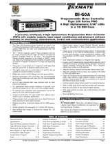
Microprocessor Based Programmable
Isolated Dual Independent Channels
Universal Signal Transmitter
Input sampling rate: 200mS.
Output signal:
TTM-2S2MM: Two analog output, 0/4~20mA or optional 0~10Vdc
TTM-2S2MM: One alalog output, DC 0/4~20mA or optional
0~10Vdc and one RS485
Output resolution: 0.6uA.
Output response time: <200mS.
Power supply: 18 to 36 V, internal protection against polarity inversion.
Power Consumption: 2W max.
Communication : Modbus RS485 RTU protocol, 4800~38400 bps
Galvanic isolation: 2 KV 1min. between input and output
Operating temperature: 0 to 55°C
Humidity: 0 to 90% RH
Electromagnetic compatibility (EMC): En 50081-2, En 50082-2
Housing material: ABS plastic. UL 94V0
Weight: 85g
Input signal: User programmable. refer to table 1.
•Thermocouple(T/C):industry standard thermocouple
types, J, K, T, E, B, R, S, N, C (ITS-90).
•Pt100:Excitation 180uA. 2 or 3 wire connection
(ITS-90 α=0.00385).
•Voltage: -60mVdc to 60mVdc or -10Vdc to 10Vdc.
•Current:0mA to 24mA
Measuring range: User programmable. Max. range see table 1.
Measuring accuracy: refer to Table 1. the accuracy is tested
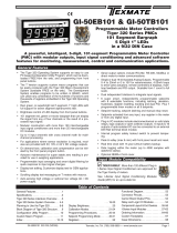
under the operating condition of 24°C±3°C. 75 mm (2.95”) 18.5 mm
87mm
83 mm
(3.43”)
(3.27”)
(0.73”)
CASE DIMENSIONS
Figure1
Accuracy is not guaranteed between 0 and 400°C
(0 and 752°F) for type B, R and S.
Range set by an internal DIP switch, see Table 2.
2
1
Table1
* Factory setting
Input signal Maximum Range Accuracy
Thermocouple J -50 to 1000°C (-58 to 1832°F)
±1°C
Thermocouple K -50 to 1370°C (-58 to 2498°F)
Thermocouple T -270 to 400°C (-454 to 752°F)
Thermocouple E -50 to 700°C (-58 to 1292°F)
Thermocouple B 0 to 1750°C (32 to 3182°F) ±2°C
Thermocouple R
-50 to 1750°C (-58 to 3182°F)
±2°C
Thermocouple S
Thermocouple N -50 to 1300°C (-58 to 2372°F)
Thermocouple C -50 to 1800°C (-58 to 3272°F)
Pt100* -200 to 600°C (-328 to 1112°F) ±0.2°C
mV -60.00 mV to 60.00 mV ±0.01mV
DC volt -10.000 to 10.000 Vdc ±1mV
DC mA 0.000 to 24.000 mAdc ±3μA
2
2
1
TTM-2S2MM and TTM-2S2MC are the DIN rail mount user
programmable Isolated two channel universal signal converters.
It accepts various input signals including mV, V, mA, PT100 and 9
different thermocouples. The measuring unit and range are also
congurable with a user-friendly TT Congurator software.
2800
Output = A(Input1) + B(Input2)
C

Texmate, Inc. Tel. (760) 598-9899 • www.texmate.comPage 2 TTM-2S2M Manual (d0006)
Installation
Acceessary
Configuration
Terminal Connection
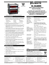
The transmitter is user congurable with the user-frendly TT Con-
guratorsoftware and URC-1020 interface cable. The lastest
version can be download free from www.texmate.com.
The URC-1020 Interface cable consist of interface converter and
USB plug. Sold separately. During conguration the transmitter
can work alone with or without connecting to a power source.
TheCongurableparametersare:
1.Input signal type: Various input signal type can be selected
among the available options.
2. Unit: Select the unit (°C or °F) of temperature. For linear input
(voltage or current), it doesn’t effect the measurement.
3. Measuring range: Denes the lowest and highest value of
measuring range. Within the range, the transmitter will convert
input signals into an scalable analogue output signal.
4. Output direction: Denes the scalable analogue
output signal to be 4 to 20mA or 20 to 4mA.
5. Fault signal on sensor break: Denes the output signal to be
(1) Downscale (<4mA).
(2) Upscale (>20mA).
(3) Cut-off. Limit the output signal within the output
range when the input is out of measuring range.
6. Offset Correction: Allows to eliminate the offset error of
measuring value.
7. ID & Baud Rate: Set device ID and communication baud rate.
8. Output Function: Select output 1 to be
(1) scale to channel 1 measuring value (PV1).
(2) Math function, which make it possible to be used as signal
addition/subtraction/division/square-root converter.
(3) High/Low comparison of PV1, PV2 the output 1 will scale to
input 1 or input 2 whichever is higher/lower than the other.
9.0/4~20mAOutputSignalCalibration:Zero and Span adjust-
ment of output signal. A power source shoule be connected as
Figure 6.
10.Measuringvalue:Read the measuring value of channel 1
(Input 1), channel 2 (input2) continually.
11.Deviceinformation:Indicate the device model, rmware
version, series number and communication status. Figure 5.
URC-1020Interfacecable
Internal DIP switch setting
Table 2.
6
5
6
Figure 6
Figure 5
Communication
Optional RS-485 interface is available for TTM-2S2MC model.
Custom input and output signal adjustment can be recalibrated
with TTConguratorsoftware.
TT-2D2MCTT-2D2MM
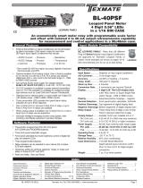
Terminal connections
RTD
RTD
WiringSpecication:
Screw tightening torque : 4.3 lb-in,
Wire range : 12~30 AWG.
Wire strip length : 6~7mm
Wiring Precaution :
1. Always keep signal wires away from power or contactor wires.
2. Transmitter's power supply should not be shared with
contactors, electrical motor and other inductive devices.
The various input signals are divided into three groups.
1.TC/RTD/mV:Thermocouple type (J, K, T, E, B, R, S, N, C),
Pt100 and voltage input in the range of -60mVdc~60mVdc.
2. Current : 0~24 mA.
3.Voltage: -10~10Vdc.
For the three different groups of input signal type, The SW1 and
SW2 should be set according to the Table 2 for each channel
separately. Open the cover o change the DIP switch setting.
12 3
TC/RTD/mV* OFF OFF ON
0~24mA ON OFF ON
-10V~10V OFF ON OFF
*Factory setting Internal DIP switch
Removing
Mounting
/