Page is loading ...

ACCURA 2300S/2350
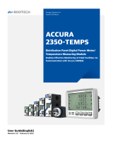
Distribution Panel Digital Power Meter/Power Measuring Module
Actually makes possible enterprise energy management
User Guide[English]
Revision 1.20 2016/12/22
(장치 N단자전압)

Distribution Panel Digital Power Meter
Accura 2300S
Accura 2300S rear
Three Phase Power Measuring Module
Three Phase Terminal
Single Phase Power Measuring Module
Single Phase Terminal
Accura 2350-3P-250A-105
TM-3P-105
Accura 2350-1P-250A-105
TM-1P-105
Accura 2350-3P-125A-90
TM-3P-90
Accura 2350-1P-125A-60
TM-1P-60
Accura 2350-3P-100A-75
TM-3P-75L
Accura 2350-1P-100A-50
TM-1P-50L
Accura 2350-3P-60A-75
TM-3P-75
Accura 2350-1P-60A-50
TM-1P-50
Accura 2350-3P-CT5A-75
Accura 2350-1PSH-50A-35
Accura 2350-1PSH-30A-35

Split-core Three Phase Power Measuring
Module
Split-core Single Phase Power
Measuring Module
Split-core Single Phase Single Hole Power Measuring
Module
Accura 2350-3PSC-250A-105
Accura 2350-1PSC-250A-105
Accura 2350-1PSCSH-800A
Accura 2350-3PSC-125A-90
Accura 2350-1PSC-125A-60
Accura 2350-1PSCSH-630A
Accura 2350-3PSC-60A-75
Accura 2350-1PSC-60A-50
Accura 2350-1PSCSH-400A

Page 4
ⓒ 2011 Rootech Inc. All Rights Reserved
Special-purpose Module
Accura 2350-DO
Accura 2350-VDC
Accura 2350-IDC
Accura 2350-GAS
Accura 2350-TEMP
Accura 2350-GW

Accura 2300S/2350 User Guide
Notice
ⓒ 2013 Rootech Inc. All Rights Reserved
Page 5
Notice
Symbol
Caution
Indicates the presence of dangerous voltage which can cause severe injury or death
to persons if proper precautions are not followed.
Warning
Alerts the user to the presence of hazards which can cause somewhat injury to
persons, damage to property or damage to the device itself, if proper precautions
are not followed.
Note
Indicates the user’s attention to installation, operating and maintenance
instructions.
Indicates alternative voltage or current.
Indicates direct voltage or current.
Installation Considerations
Installation and operation of Accura 2300S/2350 should be performed only by qualified, competent
personnel that have appropriate training and experience with high voltage and current devices.
Caution
Failure to observe the following instructions may result in severe injury or death.
During normal operation of the Accura 2300S/2350, hazardous voltages are present on its terminal strips of
voltages input and power.
Standard safety precautions are as followed while performing any installation or service work[removing PT fuses,
shorting CT secondaries, etc].
Do not access to terminal strips of the Accura 2300S/2350 after installation.

Notice
Accura 2300S/2350 User Guide
Page 6
ⓒ 2014 Rootech Inc. All Rights Reserved
Warning
Observe the following instructions, or permanent damage to the meter may occur.
Do not apply Accura 2300S/2350 to voltages and currents that exceed Input ratings of PT and CT
To use device in the other way than specified by manufacturer can cause severe damage.
Connect ground terminal to the earth ground to protect device from noise and surge.
Terminal screw torque is as followed.
- barrier-type voltage terminal:1.35Nm[1.00 ft-lbf] max.
- barrier-type digital inputs/digital output terminal:0.90Nm[0.66 ft.lbf] max.
Limitation of Liability
Rootech Inc. reserves the right to make changes in the device specifications shown in this User Guide
without notice. Rootech Inc. advises customers to obtain the latest specifications of device before giving
orders to confirm that the information being relied on by the customer is up to date.
Inc. applications assistance, customer’s system design, or infringement of patents or copyrights of
third parties by or arsing from the use of devices described herein.
Except to the extent prohibited by applicable law, under no circumstances shall Rootech Inc. be liable
for consequential damages sustained in connection with said product and Rootech Inc. neither
assumes nor authorizes any representative or other person any obligation or liability other than such
as is expressly set forth herein.
Accura EMeter, Accura 2300/2350, Accura 2300S/2350, Accura 2500, Accura 3300S/3300, Accura
3500S/3500, Accura 3550S/3550, Accura 3700, Accura 5500, Accura 7500 are trademarks of
Rootech Inc.
The information contained in this document is believed to be accurate at the time of publication,
however, Rootech Inc. assumes no responsibility for any errors which may appear here and reserves
the right to make changes without notice.
.

Accura 2300/2350 Communucation User Guide
Notice
ⓒ 2011 Rootech Inc. All Rights Reserved
Page 7
Standard Compliance
MEASURING EQUIPMENT
35DX
E258934
MSIP-REM-RTE-ACCURA 2300S
QMS-1347
KAB-QC-09

Revision History
Accura 2300S/2350 User Guide
Page 8
ⓒ 2014 Rootech Inc. All Rights Reserved
Revision History
The following versions of the Accura 2300S/2350 User Guide have been released.
Revision
Date
Description
Revision 1.00
2014. 02. 14
Initial draft
Revision 1.10
2014. 12. 23
Configuration and measurement description added.
Special-purpose module description
[Accura 2350-GAS/GW/DO/VDC/IDC/TEMP] added.
Revision 1.11
2015. 05. 21
Standard compliance updated
Revision 1.12
2015. 11. 19
Speical-purpose module arrangement modified.
Revision 1.20
2016. 12. 22
Typing error corrected, bookmark added, power event added

Accura 2300S/2350 User Guide
Contents
ⓒ 2014 Rootech Inc. All Rights Reserved
Page 9
Warranty Information
For products and software that are sold or licensed by Rootech Inc. during the period from the date
of receipt by you until the present, Rootech warrants only to the original purchaser
The purchased products shall be substantially free from material defects in material and workmanship
by Rootech for two years from the date receipt by you.
The software itself is provided “as is” without any warranty of any kind.
Limitation of Warranty
These limited Warranties shall not apply to any product that has been subject to alteration, accident,
misuse, abuse, neglect or failure to exactly follow Power Measurement's instructions for operation and
maintenance.
In order for the original purchaser to make a claim under the warranties described above, the original
purchaser must promptly contact Rootech headquarter. After receiving such notice, Rootech may either
in Rootech’s sole discretion, examine the product at the original purchaser’s site or issue shipping
instructions to the original purchaser to return the relevant product to Rootech for examination at the
original purchaser’s expense, transportation charges prepaid.
If after examining the product Rootech reasonably confirms that such examined product does not
meet the warranties, then the original purchaser’s sole remedy and Rootech’s sole obligation or
liability shall be, at Rootech’s option, to repair, replace or refund the price paid for that product.
Regardless of whether any remedy set forth herein fails of its essential purpose, except to the extent
the following limitation is prohibited by applicable law, Rootech shall not, in any event or under any
legal claim or theory, be liable to the original purchaser or any other person or entity for special,
indirect, incidental, punitive, liquidated, special or consequential damages whatsoever with respect to
any purchased product, including, without limitation, business interruption, loss of use, profit or
revenue, even if Rootech has been advised of the possibility of such damages. To the extent that a
limitation or exclusion of consequential damages are prohibited by app
licable law, then Rootech’s liability shall be limited to twice the amount of the relevant purchased
product.
Rootech shall not be liable for any claim- other than a claim solely for the breach of one of the above

Contents
Accura 2300S/2350 User Guide
Page 10
ⓒ 2014 Rootech Inc. All Rights Reserved
warranties that is made in accordance with the above described procedures- made by the original
purchaser, its employees, agents, or contractors for any loss, damage, or expense incurred due to,
caused by, or related to any purchased product
Any technical assistance provided by Rootech's personnel or representatives in system design shall be
deemed to be a proposal and not a recommendation. The responsibility for determining the feasibility
of such proposals rests with the original purchaser and should be tested by the original purchaser.
It is the original purchaser’s responsibility to determine the suitability of any product and associated
documentation for its purposes. The original purchaser acknowledges that 100% "up" time is not
realizable because of possible hardware or software defects. The original purchaser recognizes that
such defects and failures may cause inaccuracies or malfunctions.
Only the terms expressed in these limited Warranties shall apply and no distributor, corporation or
other entity, individual or employee of Rootech or any other entity is authorized to amend, modify or
extend the Warranties in any way.

Accura 2300S/2350 User Guide
Contents
ⓒ 2014 Rootech Inc. All Rights Reserved
Page 11
Contents
Chapter 1 Introduction .................................................................................................................... 19
Overview ........................................................................................................................................ 19
Application ...................................................................................................................................... 22
Device Lineup.................................................................................................................................. 23
Distribution Panel Digital Meter/Power Measuring Module ........................................................... 23
Special-Purpose Module ............................................................................................................ 24
Installation Example .................................................................................................................. 25
Features .................................................................................................................................... 27
Chapter 2 Installation ...................................................................................................................... 33
Environmental Conditions ................................................................................................................ 33
Before you begin ............................................................................................................................. 34
Meter Overview ......................................................................................................................... 34
Components ............................................................................................................................. 36
Dimension ................................................................................................................................ 38
Installation Single Diagram ........................................................................................................ 44
Step 1: Mounting ............................................................................................................................. 47
Accura 2300S Mounting ............................................................................................................ 47
Accura 2350-3P Three Phase Power Measuring Module Mounting ............................................... 48
Accura 2350-1P Single Phase Power Measuring Module Mounting .............................................. 53
Accura 2350-3PSC Split-core Three Phase Power Measuring Module Mounting ............................ 58
Accura 2350-1PSC Split-core Single Phase Power Measuring Module Mounting ........................... 63
Accura 2350-1PSCSH Split-core Single Phase Single Hole Power Measuring Module Mounting ..... 68
Step 2: Accura 2300S Wiring ........................................................................................................... 72
Accura 2300S Voltage Wiring .................................................................................................... 72
Accura 2300S Digital Input/Output Wiring ................................................................................. 77
Step 3: Accura 2350 Through-hole Wiring ........................................................................................ 80
Accura 2350 Power Measuring Module Through-hole Wiring ...................................................... 80
Accura 2350 Single Phase Single Hole Power Measuring Module Current Through-hole Wiring .... 85
Step 4: Accura 2300S/2350 Internal Communication[6C Telephone Line] .......................................... 88
Step 5: Accura 2300S External Communication[Ethernet, RS485] ....................................................... 90
Ethernet Communication ........................................................................................................... 90
RS485 Communication .............................................................................................................. 92
Step 6: Accura 2300S Power Supply and Ground .............................................................................. 93
Power Supply............................................................................................................................. 93

Contents
Accura 2300S/2350 User Guide
Page 12
ⓒ 2014 Rootech Inc. All Rights Reserved
Ground Terminal ....................................................................................................................... 93
Chapter 3 Accura 2350 Operation/Setup .......................................................................................... 94
Operation Mode ....................................................................................................................... 94
Button Function ......................................................................................................................... 94
Accura 2350-3P[3PSC] Three Phase Power Measuring Module .......................................................... 95
Application Model ..................................................................................................................... 95
Display Mode ............................................................................................................................ 96
Setup Mode .............................................................................................................................. 98
Accura 2350-1P[1PSC] Single Phase Power Measuring Module ........................................................ 108
Application Model ................................................................................................................... 108
Display Mode .......................................................................................................................... 108
Setup Mode ............................................................................................................................ 110
Accura 2350-1PSCSH Split-core Single Phase Single Hole Power Measuring Module ........................ 119
Application Model ................................................................................................................... 119
Display Mode .......................................................................................................................... 119
Setup Mode ............................................................................................................................ 121
Chapter 4 Accura 2300S Operation/Setup ...................................................................................... 131
Operation Mode ..................................................................................................................... 131
LED ........................................................................................................................................ 132
Button Function ....................................................................................................................... 132
Display Mode ................................................................................................................................ 134
Front Display ........................................................................................................................... 134
Accura 2350 Module ID Selection ............................................................................................ 137
Display Screen ........................................................................................................................ 138
Voltage/Current/Power/Energy[V∙I∙P∙E]...................................................................................... 139
Voltage/Frequency[V∙FREQ] ..................................................................................................... 140
Current[I] ................................................................................................................................ 140
Power/Power Factor[P∙PF] ......................................................................................................... 141
Demand[DEMAND] ................................................................................................................. 141
Active Energy[ENERGY] ............................................................................................................ 142
Leakage Current[MODULE] ..................................................................................................... 142
RSTP Information[INFO] ........................................................................................................... 143
Temperature/Time[ETC] ........................................................................................................... 144
Setup Mode................................................................................................................................... 145
Setup Mode Display Screen ...................................................................................................... 147
Meter ...................................................................................................................................... 148

Accura 2300S/2350 User Guide
Contents
ⓒ 2014 Rootech Inc. All Rights Reserved
Page 13
Event[EVENT] .......................................................................................................................... 154
RS485 Communication[COMM] ............................................................................................... 165
Ethernet Communication[NETWORK] ....................................................................................... 166
Reset[RESET] ............................................................................................................................ 169
Display[DISPLAY] ..................................................................................................................... 170
Accura 2350 Module ID[MODULE] .......................................................................................... 172
Accura 2350-1P Three Phase Device Group[MODULE] ............................................................. 177
Information[INFO] ................................................................................................................... 180
Digital Input/Output[ETC] ........................................................................................................ 181
Event Log Mode............................................................................................................................. 186
Start Event & End Event ............................................................................................................ 186
Start Event Alarm On ............................................................................................................... 186
Start Event Alarm Off ............................................................................................................... 186
Button Function ....................................................................................................................... 187
Event Log Number Assignment ................................................................................................. 188
Dip Event Log .......................................................................................................................... 189
Swell Event Log ....................................................................................................................... 189
Fuse Fail Event Log .................................................................................................................. 190
Temperature Event Log ............................................................................................................ 191
Current Event Log .................................................................................................................... 191
Leakage Current Event Log ...................................................................................................... 192
Demand Current Event Log ...................................................................................................... 193
Required Configuration Step .......................................................................................................... 194
Step 1: Accura 2300S Connection, PT Rating ............................................................................ 194
Step 2: Accura 2350 Module ID Auto-Assignment/Update ........................................................ 196
Step 3: Accura 2300S Ethernet ................................................................................................. 199
Chapter 5 Measurement Description ............................................................................................... 200
General Measurement Factor ......................................................................................................... 200
Measurement Event Factor ............................................................................................................. 203
Measurement for Voltage Wiring .................................................................................................... 204
Three Phase Four Wires ........................................................................................................... 204
Three Phase Three Wires ......................................................................................................... 205
Single Phase Three Wires ......................................................................................................... 207
Single Phase Two Wires............................................................................................................ 208
Power Measurement for Each Phase ............................................................................................... 209
Method 1[Fundamental Calculation] ........................................................................................ 209

Contents
Accura 2300S/2350 User Guide
Page 14
ⓒ 2014 Rootech Inc. All Rights Reserved
Method 2[Harmonic Calculation] ............................................................................................. 209
Three Phase Total Power Measurement ........................................................................................... 210
Method 1[Vector Sum] ............................................................................................................. 210
Method 2[Arithmetic Sum] ........................................................................................................ 211
Power Factor[PF] Measurement ....................................................................................................... 212
Current Phase LEAD/LAG Measurement ......................................................................................... 212
Dip[Sag]/Swell Measurement ......................................................................................................... 213
Half-cycle Refreshed 1-cycle RMS ............................................................................................. 213
Dip[Sag]/Swell Detection ......................................................................................................... 213
Demand Measurement .................................................................................................................. 214
Demand ................................................................................................................................. 214
Prediction Demand .................................................................................................................. 214
Unbalance[NEMA MG1] ................................................................................................................ 215
Line-Neutral Voltage Unbalance .............................................................................................. 215
Line-Line Voltage Unbalance.................................................................................................... 215
Sequence Unbalance ..................................................................................................................... 215
Negative Sequence Unbalance Ratio ........................................................................................ 216
Zero Sequence Unbalance Ratio .............................................................................................. 216
ZCT Leakage Current Measurement ............................................................................................... 216
“Half-cycle RMS” Measurement[Default] ................................................................................... 216
“One-cycle Fundamental Wave RMS” Measurement .................................................................. 216
Aggregation .................................................................................................................................. 217
Fixed aggregation ................................................................................................................... 217
Customed aggregation ............................................................................................................ 218
Event aggregation ................................................................................................................... 219
Aggregation Data Collection .................................................................................................... 219
APPENDIX A Specification .............................................................................................................. 220
APPENDIX B Standard Compliance ................................................................................................. 225
APPENDIX C Accuracy/Reliability .................................................................................................... 226
Accuracy ................................................................................................................................. 226
Reliability ................................................................................................................................ 227
APPENDIX D Ordering Information ................................................................................................. 228
Distribution Panel Digital Power Meter/Power Measuring Module ............................................... 228
Special-Purpose Module .......................................................................................................... 229
INDEX.......................................................................................................................................... 230

Accura 2300S/2350 User Guide
Contents
ⓒ 2014 Rootech Inc. All Rights Reserved
Page 15
Figures
Fig 1.1 Accura 2350-3P Through-hole Currrent Sensing Structure ............................................... 20
Fig 1.2 Accura 2350-3P[1P] Length Compatibility with MCCB/ELB Rating .................................... 21
Fig 1.3 Accura 2350-3PSC[1PSC] Split-core Three Phase[Single Phase] Power Measuring Module
Installation ................................................................................................................................ 21
Fig 1.4 Accura 2300S/2350-3P[1P] Power Measuring Module Installation Example ...................... 25
Fig 1.5 Split-core Power Measuring Module Installation Example ................................................. 26
Fig 2.1 Accura 2300S Front ....................................................................................................... 34
Fig 2.2 Accura 2300S Side ........................................................................................................ 34
Fig 2.3 Accura 2300S Rear ........................................................................................................ 34
Fig 2.4 Accura 2350-3P[1P] Power Measuring Module ................................................................ 35
Fig 2.5 Accura 2350-3PSC[1PSC, 1PSCSH] Split-core Power Measuring Module........................... 35
Fig 2.6 Accura 2300S Components ............................................................................................ 36
Fig 2.7 Accura 2350-3P Three Phase Power Measuring Module Components ............................... 36
Fig 2.8 Accura 2350-1P Single Phase Power Measuring Module Components .............................. 36
Fig 2.9 Accura 2350-1PSH Single Phase Single Hole Power Measuring Module Components ........ 36
Fig 2.10 Accura 2350-1PSC Split-core Single Phase Power Measuring Module Component .......... 37
Fig 2.11 Accura 2350-1PSCSH Split-core Single Phase Single Hole Power Measuring Module
Component............................................................................................................................... 37
Fig 2.12 TM-3P Three Phase Terminal Component ...................................................................... 37
Fig 2.13 TM-1P Single Phase Terminal Component ..................................................................... 37
Fig 2.14 Accura 2300S Front Dimension .................................................................................... 38
Fig 2.15 Accura 2300S Side Dimension ..................................................................................... 38
Fig 2.16 Accura 2300S Rear Dimension ..................................................................................... 38
Fig 2.17 Accura 2350-3P Three Phase Power Measuring Module Dimension ................................ 39
Fig 2.18 TM-3P Three Phase Terminal Dimension ....................................................................... 39
Fig 2.19 Accura 2350-1P Single Phase Power Measuring Module ................................................ 40
Fig 2.20 TM-1P Single Phase Terminal ........................................................................................ 40
Fig 2.21 Accura 2350-1PSH Single Phase Single Hole Power Measuring Module .......................... 41
Fig 2.22 Accura 2350-3PSC Split-core Three Phase Power Measuring Module .............................. 41
Fig 2.23 Accura 2350-1PSC Split-core Single Phase Power Measuring Module ............................. 42
Fig 2.24 Accura 2350-1PSCSH Split-core Single Phase Single Hole Power Measuring Module ....... 42
Fig 2.25 Accura 2300S/2350-3P[1P] Power Measuring Module Installation Diagram.................... 44
Fig 2.26 Accura 2300S/2350-3PSC[1PSC, 1PSCSH] Power Measuring Module Installation Diagram
................................................................................................................................................ 45

Contents
Accura 2300S/2350 User Guide
Page 16
ⓒ 2014 Rootech Inc. All Rights Reserved
Fig 2.27 Accura 2300S Mounting[ANSI 4’’] ................................................................................ 47
Fig 2.28 Accura 2300S Mounting[DIN96] ................................................................................... 47
Fig 2.29 Accura 2350-3P Three Phase Power Measuring Module Mounting .................................. 48
Fig 2.30 Accura 2350-3P Three Phase Power Measuring Module/Terminal Cutout ........................ 49
Fig 2.31 Accura 2350-3P Three Phase Power Measuring Module Mounting Plate/Terminal Cutout 51
Fig 2.32 Accura 2350-1P Single Phase Power Measuring Panel Module Mounting ........................ 53
Fig 2.33 Accura 2350-1P Single Phase Power Measuring Module/Terminal Cutout ....................... 54
Fig 2.34 Accura 2350-1P Single Phase Power Measuring Module Mounting Plate/Terminal Cutout 56
Fig 2.35 Accura 2350-3PSC Split-core Power Measuring Module New Installation ........................ 58
Fig 2.36 Accura 2350-3PSC Split-core Three Phase Power Measuring Module Cutout ................... 59
Fig 2.37 Accura 2350-3PSC Mounting Plate Cutout .................................................................... 61
Fig 2.38 Accura 2350-3PSC Split-core Power Measuring Module Remodeling Installation ............. 62
Fig 2.39 Accura 2350-1PSC Split-core Power Measuring Module New Installation ........................ 63
Fig 2.40 Accura 2350-1PSC Split-core Single Phase Power Measuring Module Cutout .................. 64
Fig 2.41 Accura 2350-1PSC Mounting Plate Cutout .................................................................... 66
Fig 2.42 Accura 2350-1PSC Split-core Power Measuring Module Remodeling Installation ............. 67
Fig 2.43 Accura 2350-1PSCSH Split-core Power Measuring Module New Installation.................... 68
Fig 2.44 Accura 2350-1PSCSH Split-core Power Measuring Module Cutout.................................. 69
Fig 2.45 Accura 2350-1PSCSH Split-core Power Measuring Module Cutout.................................. 70
Fig 2.46 Accura 2350-1PSCSH Split-core Power Measuring Module Remodeling Installation ......... 71
Fig 2.47 Accura 2300S Voltage Wiring ....................................................................................... 72
Fig 2.48 Three Phase 4 Wires, Direct Wiring ............................................................................... 73
Fig 2.49 Three Phase 4 Wires, 3PT Wiring .................................................................................. 73
Fig 2.50 Three Phase 3 Wires, Direct Wiring ............................................................................... 74
Fig 2.51 Three Phase 3 Wires, 2PT Wiring .................................................................................. 74
Fig 2.52 Single Phase 3 Wires, Direct Wiring .............................................................................. 75
Fig 2.53 Single Phase 3 Wires, 2PT Wiring ................................................................................. 75
Fig 2.54 Single Phase 2 Wires, Direct Wiring .............................................................................. 76
Fig 2.55 Single Phase 2 Wires, 1PT Wiring ................................................................................. 76
Fig 2.56 Accura 2300S Digital Input/Output Channel ................................................................. 77
Fig 2.57 Digital Input ................................................................................................................ 78
Fig 2.58 DC Relay Application ................................................................................................... 79
Fig 2.59 AC Relay Application .................................................................................................... 79
Fig 2.60 Three Phase 4 Wires/3 Wires, Direct Through-hole Wiring ............................................. 82
Fig 2.61 Three Phase 4 Wires/3 wires, 3CT Through-hole Wiring ................................................ 82
Fig 2.62 Three Phase 3 wires, 2CT Through-hole Wiring ............................................................. 83

Accura 2300S/2350 User Guide
Contents
ⓒ 2014 Rootech Inc. All Rights Reserved
Page 17
Fig 2.63 Single Phase LN[Line to Neutral] Through-hole Wiring ................................................... 84
Fig 2.64 Single Phase LL[Line to Line] Through-hole Wiring ......................................................... 84
Fig 2.65 Three Phase 4 Wires/3 Wires, Single hole 3 Module Through-hole Wiring ...................... 86
Fig 2.66 Three Phase 3 Wires, Single hole 2 Module Through-hole Wiring ................................... 86
Fig 2.67 Single Phase LN[Line to Neutral] Single hole Module Through-hole Wiring ..................... 87
Fig 2.68 Single Phase LL[Line to Line] Single hole Module Through-hole Wiring ........................... 87
Fig 2.69 Accura 2300S/2350 Combination Example of Communication ..................................... 88
Fig 2.70 Accura 2300S Ethernet Communication Port ................................................................. 90
Fig 2.71 Accura 2300S Ethernet Communication ........................................................................ 91
Fig 2.72 Accura 2300S RS485 Communication .......................................................................... 92
Fig 2.73 Accura 2300S RS485 Communication Connection ........................................................ 92
Fig 2.74 Accura 2300S Power Supply ......................................................................................... 93
Fig 4.1 Accura 2300S Front ..................................................................................................... 131
Fig 4.2 Display Mode .............................................................................................................. 132
Fig 4.3 Setup Mode ................................................................................................................. 133
Fig 4.4 Event Log Mode ........................................................................................................... 133
Fig 4.5 Accura 2300S Front Overview ...................................................................................... 134
Fig 4.6 Accura 2300S Temperature Sensor ............................................................................... 136
Fig 4.7 Accura 2350 Module ID Selection at Upper Part of LCD Screen ...................................... 137
Fig 4.8 Voltage/Current/Power/Energy Display Screen .............................................................. 139
Fig 4.9 Voltage/Current/Power/Energy for Each Phase Display Screen ....................................... 139
Fig 4.10 Line to Line Voltage Display Screen ............................................................................. 140
Fig 4.11 Line to Neutral Current Display Screen ........................................................................ 140
Fig 4.12 Power Display Screen ................................................................................................. 141
Fig 4.13 Demand Active Power Display Screen ......................................................................... 141
Fig 4.14 Net Energy Display Screen.......................................................................................... 142
Fig 4.15 Leakage Current Display Screen ................................................................................. 142
Fig 4.16 Ethernet Conncetion Status Display Screen .................................................................. 143
Fig 4.17 Temperature around Accura 2300S Display Screen ...................................................... 144
Fig 4.18 Dip Event Configuration[Three Phase 3 Wires] ............................................................. 155
Fig 4.19 Dip Event Configuration[Three Phase 3 Wires] ............................................................. 155
Fig 4.20 Swell Event Configuration[Three phase 4 wires] ........................................................... 157
Fig 4.21 Swell Event Configuration[Three phase 3 wires] ........................................................... 157
Fig 4.22 Dip[Sag] Event Alarm Screen ...................................................................................... 186
Fig 4.23 Swell Event Alarm Screen ........................................................................................... 186
Fig 4.24 Event Log Number ..................................................................................................... 188

Contents
Accura 2300S/2350 User Guide
Page 18
ⓒ 2014 Rootech Inc. All Rights Reserved
Fig 5.1 3PT, 3CT Wiring, Wiring Mode = 3P4U (3P4W Wiring) .................................................. 204
Fig 5.2 2PT, 3CT Wiring, Wiring Mode = 3P3U (3P3W Wiring) .................................................. 205
Fig 5.3 2PT, 2CT Wiring, Wiring Mode = 3P3U (3P3W Wiring) .................................................. 205
Fig 5.4 2PT, 2CT Wiring, Wiring Mode = 1P3U (1P3W Wiring) .................................................. 207
Fig 5.5 1PT, 1CT Wiring, Wiring Mode = 1P2U (1P2W Wiring) .................................................. 208
Fig 5.6 Vector Diagram for Vector Sum Apparent Power ............................................................ 210
Fig 5.7 Vector Diagram for Arithmetic Sum Apparent Power ...................................................... 211
Fig 5.8 Power Sign and Current Phase LEAD/LAG ..................................................................... 212
Fig 5.9 Half-cycle Refreshed 1-cycle RMS Calculation ................................................................ 213
Fig 5.10 Voltage Dip[Sag] Detection ......................................................................................... 213
Fig 5.11 Demand Calculation .................................................................................................. 214
Fig 5.12 Prediction Demand Calculation .................................................................................. 214
Fig 5.13 Symmetrical Components ........................................................................................... 215
Fig 5.14 Aggregation Process .................................................................................................. 217

Accura 2300S/2350 User Guide
Chapter 1 Introduction
ⓒ 2014 Rootech Inc. All Rights Reserved
Page 19
Chapter 1 Introduction
Overview
Energy Management Paradigm Shift from Main Load to Branch Load
Until now for stable power supply, energy management has been used for a long time on orientation
of mainly switchgear panels such as main feeder, ACB and VCB. however at the time of both the sharp
increase of energy cost and preparations for CO2 emission reduction policy, demand of energy
management on orientation of distribution panels which comprise incoming feeder and the branch
loads[or circuits] is increasingly growing in manufacturing plants, IDC center, building and etc.
Limit of Application of the existing Digital Power Meter to Distribution Panel
To apply the digital power meter which is long used in the existing switchgear panel to distribution
panel has had the limit caused by narrow space, hazardous wiring of voltage and current, and high
installation cost. This fundamentally makes it difficult for energy management supervisor to access to
the energy information of branch loads in distribution panel.
Distribution Panel Digital Power Meter Speicalized for Branch Load Management
Distribution panel digital power meter comprises both Apccura 2300S[digital power meter] which is
mounted on front of distribution panel, and Accura 2350[power measuring module] which is mounted
in branch loads inside the panel. Accura 2300S collects power data from several Accura 2350s on
RS485 communication and displays only measurements of one Accura 2350 selected on its LCD
screen. This provides energy management supervisor with the power quality information of branch
loads which was impossible to identify.
±0.2% Reading/IEC62053-22 Class 0.5S[Class 0.2S 1] Accuracy
Recently enterprise energy management system is essential for effective energy use and preventive
management to prepare CO2 emission management in plant, data center and building. The key
factor to determine reliability of the energy management is measuring accuracy. Accura 2300S/2350
makes 0.2% high accuracy measurements for voltage and current, and conforms to IEC62053-22
class 0.5S[Class 0.2S 1] for power and energy. This makes it possible to precisely analyze and
diagnose various problems with energy management and power facilities.
1 Split-core single phase single hole power measuring module, Accura 2350-1PSCSH-800A/630A/400A
conforms to IEC62053-22 Class 0.2S.

Chapter 1 Introduction
Accura 2300S/2350 User Guide
Page 20
ⓒ 2014 Rootech Inc. All Rights Reserved
Dip[Sag]/Swell[IEC61000-4-30 Class B], Power Quality
Accura 2300S provides various power quality information such as Dip[Sag], Swell, harmonic information [up to
63 harmonic], Crest factor, K factor, and unbalance. This makes it possible for energy management supervisor
to easily find the change of power quality in the power facility. Quality information conforms to IEC61000-4-30.
Aggregation Interval Maximum/Minimum/Average Information
Accura 2300S provides the average value that corresponds to 0.5 second interval from the
measurement value per cycle unit. Based on 0.5 second interval average value, Accura 2300S
provides the maximum/minimum/average of 1 second, 5 seconds, 1 minute, 5 minutes, 1 hour and
6 hours intervals. This measurement interval that is longer than 0.5 second means the Aggregation
Interval.
Accura 2300S provides not only the measuring parameter information, but also statistic information
(maximum, minimum, average) of voltage, current and power by communication. This includes the
information of measuring parameter which often changes. So this makes it possible to accurate trend-
analyzing about voltage, current and power.
CE/UL Safety and Reliability
The structure-framework, circuit, fire of Accura 2300S/2350 conforms to standard, CE[EN61326-1,
EN61326-2-1] and UL[UL61010-1].
Safety Guarantee of Installation by Through-hole Structure
Accura 2350-3P[1P] three phase[single phase] power measuring module is structured with Through-
hole current sensing without any electrical contacts, which guarantees safety of electrical accident and
simplifies installation. TM-3P is three phase terminal for helping wiring.
Fig 1.1 Accura 2350-3P Through-hole Currrent Sensing Structure
/