
LIFT CORP.
11921 Slauson Avenue.
Santa Fe Springs, CA. 90670
(800) 227-4116
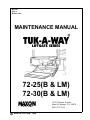
72-25(B & LM)
72-30(B & LM)
C MAXON Lift Corp. 1999
LIFTGATE SERIES
M-95-09
REV. C
MARCH 1999
MAINTENANCE MANUAL

LIFT CORP.
11921 Slauson Ave.
Santa Fe Springs, CA. 90670
CUSTOMER SERVICE:
TELEPHONE (562) 464-0099 TOLL FREE (800) 227-4116
FAX: (888) 771-7713
WARRANTY POLICY & PROCEDURE
NOTE: Check with Customer Service for updated versions
of Manuals on an annual basis.
NEW LIFTGATE WARRANTY
Term of Warranty: 2 Years from Date of In-Service
Type of Warranty: Full Parts and Labor
MAXON agrees to replace any components which are found to be defective during the first 2
years of service, and will reimburse for labor based on MAXON’s Liftgate Warranty Flat Rate Labor
Schedule. (Call MAXON Customer Service for a copy).
All claims for warranty must be received within 30 Days of the repair date, and include the
following information:
1. Liftgate Model Number
2. Liftgate Serial Number
3. Detailed Description of Problem
4. Corrective Action Taken, and Date of Repair.
5. Parts used for Repair, Including MAXON Part Number(s).
6. MAXON R.M.A. # and/or Authorization # if applicable (see below).
7. Person contacted at MAXON if applicable.
All warranty repairs must be performed by an authorized MAXON warranty station. For major
repairs, MAXON Customer Service must be notified and an “Authorization Number” obtained. Major
repairs would generally be considered repairs made to the structural assembly of the liftgate and/or
repairs not outlined in the MAXON Liftgate Warranty Flat Rate Schedule.
Major components (i.e. hydraulic pumps, cylinders, valves, or failed structural parts) must be
returned, freight pre-paid, prior to the claim being processed. To ensure timely processing of these
warranty claims, an R.M.A. (Returned Merchandise Authorization) number must be obtained from
MAXON Customer Service prior to the return of any defective part. Defective Parts must be returned
within 60 days of the claim date for consideration to:
MAXON Lift Corp.
16205 Distribution Way, Cerritos, CA 90703
Attn: RMA#__
MAXON’s warranty policy does not include the reimbursement for travel time, towing, vehicle
rental, service calls, oil, batteries, defects due to misuse or abuse, or loss of income due to downtime.
Fabrication of parts, which are available from MAXON, are also not covered.
MAXON’s Flat Rate Labor Schedule takes into consideration the time required for diagnosis of a
problem.
PURCHASE PART W ARRANTY
Term of Warranty: 1 Year from Date of Purchase
Type of Warranty: Part Replacement
MAXON will guarantee all returned genuine replacement parts upon receipt and inspection of
parts and invoice.

Table of Contents
INTRODUCTION....................................................................................................... PAGE 4
WARNING ................................................................................................................. PAGE 5
PERIODIC MAINTENANCE CHECKLIST................................................................. PAGE 6
DECALS .................................................................................................................... PAGE 7
HAND PUMP STANDARD ........................................................................................ PAGE 8
SAFETY HOOK ......................................................................................................... PAGE 9
REPLACING PLATFORM TORSION SPRING ....................................................... PAGE 10
PLATFORM ADJUSTMENT .................................................................................... PAGE 12
HINGE PIN LOCATION ........................................................................................... PAGE 13
72-25/30LM ASSEMBLY ......................................................................................... PAGE 14
GRAVITY DOWN SECTION ............................................................... PAGE 17
HYDRAULIC ASSEMBLY, OLD STYLE PUMP ....................................................... PAGE 18
HYDRAULIC ASSEMBLY, SLIMLINE PUMP .......................................................... PAGE 19
PUMP ASSEMBLY, GRAVITY DOWN, OLD STYLE ............................................... PAGE 20
PUMP ASSEMBLY, GRAVITY DOWN, NEW STYLE.............................................. PAGE 22
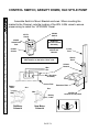
CONTROL SWITCH, GRAVITY DOWN, OLD STYLE PUMP ................................ PAGE 24
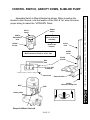
CONTROL SWITCH, GRAVITY DOWN, SLIMLINE PUMP .................................... PAGE 25
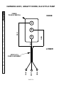
HARNESS ASSY., GRAVITY DOWN, OLD STYLE PUMP ..................................... PAGE 26
HARNESS ASSY., GRAVITY DOWN, SLIMLINE PUMP ........................................ PAGE 27
WIRE CONNECTIONS, GRAVITY DN., OLD STYLE PUMP ................................. PAGE 28
WIRE CONNECTIONS, GRAVITY DN., SLIMLINE PUMP ..................................... PAGE 29
PUMP ENCLOSURE, OLD STYLE PUMP ............................................................. PAGE 30
POWER DOWN SECTION .................................................................PAGE 32
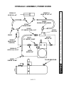
HYDRAULIC ASSEMBLY, POWER DOWN ............................................................ PAGE 33
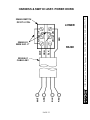
CONTROL SWITCH, POWER DOWN ................................................................... PAGE 34
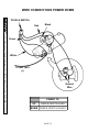
HARNESS & SWITCH ASSY. POWER DOWN ...................................................... PAGE 35
WIRE CONNECTIONS POWER DOWN ................................................................ PAGE 36
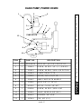
HAND PUMP, POWER DOWN ............................................................................... PAGE 37
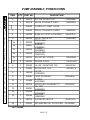
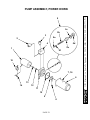
PUMP ASSEMBLY, POWER DOWN ...................................................................... PAGE 38
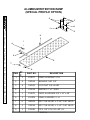
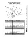
ALUMINUM RETENTION RAMP ............................................................................ PAGE 40
TROUBLESHOOTING ........................................................................ PAGE 42
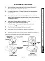
PLATFORM WILL NOT RAISE ............................................................................... PAGE 43
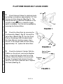
PLATFORM RAISES BUT LEAKS DOWN ............................................................. PAGE 44
PLATFORM RAISES PARTIALLY AND STOPS ..................................................... PAGE 45
LIFTGATE WILL NOT LIFT RATED CAPACITY ..................................................... PAGE 46
PLATFORM RAISES SLOWLY ............................................................................... PAGE 47
PLATFORM WILL NOT LOWER............................................................................. PAGE 48

11921 Slauson Ave. Santa Fe Springs, CA. 90670 (800) 227-4116 FAX (888) 771-7713
PAGE 4
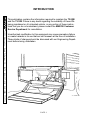
INTRODUCTION
This publication contains the information required to maintain the 72-25B
and the 72-30B If there is any doubt regarding the suitability of these lifts
being maintained on its intended vehicle, or any portion of these instruc-
tions that you do not understand, please contact the MAXON Customer
Service Department for consultation.
Unauthorized modification to this equipment may cause premature failure
or create hazards in its use that are not foreseen at the time of installation.
These kinds of changes should be discussed with our Engineering Depart-
ment before being undertaken.

11921 Slauson Ave. Santa Fe Springs, CA. 90670 (800) 227-4116 FAX (888) 771-7713
PAGE 5
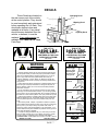
1. Read the Maintenance Manual and understand it thoroughly before any maintenance of
this unit is done.
2. Read the YELLOW urgent warning decal on the side of the vehicle close to the unit before
operating.
3. If decals are dirty, clean them. If decals are defaced or missing, replace them. Free replace-
ments are available from the manufacturer. See information at the end of the Warnings
4. Be aware that the safety and location of other people or objects should be considered
before operation of this unit. Stand to one side of platform while operating this unit.
5. Do not stand under, or have any foreign object under the Platform when lowering. Be sure
that the lowering of the Platform and/or Flipover will miss your feet!
6. Keep fingers, hands, arms, legs, and feet clear of moving parts when operating this unit.
7. If during your maintenance procedure, it becomes necessary to ride the platform, keep your
feet and any foreign objects clear of the rear edge of the platform. Otherwise your feet or
the foreign objects could become trapped between the edge of the platform and the vehicle
bed.
8. Inspect all Roll Pins monthly, to insure that they are not broken. Replace if broken.
9. Inspect all hydraulic hoses and fittings annually. Check for cracks and deterioration, and
replace if necessary.
10. Disconnect battery when replacing parts or servicing.
11. Do not allow children to ride, play with, or operate this unit.
12. In the event of an emergency while operating the unit, release the toggle switch and the unit
will stop immediately.
13. A properly installed Lift should operate smoothly and the only noise during the operation of
this unit should be from the Pump Unit during the raising of the Platform. Any scraping,
grating or audible indications of rough operation will need investigating. The cause will need
resolving before any further deterioration of performance occurs.
14. Use only Maxon Authorized Parts for replacement. Replacement parts should be ordered
from:
MAXON LIFT CORP. Parts Department
11921 Slauson Ave., Santa Fe Springs, Ca. 90670
Phone: (800) 227-4116
WARNING

11921 Slauson Ave. Santa Fe Springs, CA. 90670 (800) 227-4116 FAX (888) 771-7713
PAGE 6
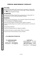
* COLD WEATHER OPERATION
OIL SPECIFICATIONS:
Grade ISO-(32)
Gravity, API - 29.5 Degrees
Pour Point, F- (-54 Degrees)
VISCOSITY:
@ 40 Degrees C - 31.2 cSt
@100 Degrees C - 6.2 cSt
VISCOSITY INDEX - 154 VI
Flash Point, F - 325 Degrees
Visually check the complete unit for excessive wear, worn parts or broken welds.
Check all Hinge Pins for excessive wear or broken welds. For parts replacement,
see the Assembly Breakdown Drawings.
PERIODIC MAINTENANCE CHECKLIST
Check the oil in the Pump Reservoir. The oil should be Grade ISO-(32) Hydraulic
Fluid. *See below for Cold Weather operation.
Check Hoses and Fittings for scuffing and leaks. Replace if necessary.
Check the electrical wiring for worn insulation, and the terminals for corrosion and
secure fit.
Check all bolts for tightness.
Check that all Warning Decals are in place and readable.
Check that all roll pins are properly installed. Replace if necessary.
Inspect the Hook & Chain Assembly for proper operation.
Annually
Quarterly
Six Months
Visually check the Platform Hinge Pins for excessive wear or broken welds. For
parts replacement, see the Assembly Breakdown Drawings.

11921 Slauson Ave. Santa Fe Springs, CA. 90670 (800) 227-4116 FAX (888) 771-7713
PAGE 7
DECALS
These Decals are located on
the rear corner post of the vehicle,
at the control position. They should
be read completely and understood
before operating the Lift Gate. They
should also be kept clean and
readable at all times. If any decal
should become detached from the
vehicle, or defaced, it must be
replaced. Free replacements are
available from: MAXON Lift Corp.,
Parts Dept.
Operating Decal
Capacity Decal
Warning Decal
3000 LBS.
P/N 220388
THE MAXIMUM CAPACITY OF
THIS LIFT IS
WHEN THE LOAD IS
CENTERED ON THE LOAD
CARRYING PLATFORM
THE MAXIMUM CAPACITY OF
THIS LIFT IS
WHEN THE LOAD IS
CENTERED ON THE LOAD
CARRYING PLATFORM
2500 LBS.
P/N 220382
Operating Instructions
Units
1
2
3
4
5
LIFT CORP.
P/N 251867
To Tuck unit away,
reverse steps 1,2,& 3.
Activate toggle
switch to Raise or
Lower platform
Open
Flipover
Open
Platform
Depress handle &
activate Toggle
Switch to lower
stowed liftgate.
This point must
touch ground.
WARNING
READ CAREFULLY
Improper operation of this Lift can result in serious personal injury.
Do not operate unless you have been properly instructed and have
read, and are familiar with the operating instructions. If you do not
have a copy of the instructions, please obtain them from your
employer, distributor, or lessor, before you attempt to operate Lift.
Be certain that the vehicle is properly and securely braked before
using the Lift.
Always inspect this Lift for maintenance or damage before using it. If
there are signs of improper maintenance, damage to vital parts, or
slippery Platform surface, do not use the Lift until these problems
have been corrected.
Do not overload the Lift. The load limit is based on evenly distrib-
uted cargo over the entire Platform surface. If you are using a pallet
jack, be sure it can be maneuvered safely. Do not operate a forklift on
the Platform or travel with the platform in an open position at any time.
Load should be placed in a stable position close to the edge of the
Platform nearest the truck. The heaviest portion of the load should
never be placed beyond the center of the Platform away from the
truck.
Never allow yourself, a helper, or bystander to stand in a position
where a falling load could land on either of you. Also do not allow any
part of yours or your helpers body to be placed under, within, or
around any portion of the moving liftgate, or its mechanisms, or in a
position that would trap them between the platform and the ground or
truck when the liftgate is operated.
If a helper is riding the Platform with you, make sure you are both
doing so safely and that you are not in danger of coming in contact
with any moving or potentially moving obstacles. USE GOOD
COMMON SENSE. If load appears to be unsafe, do not lift or lower it.
MAXON LIFT CORP. PART NO. 264081
!
!
P/N 250993

11921 Slauson Ave. Santa Fe Springs, CA. 90670 (800) 227-4116 FAX (888) 771-7713
PAGE 8
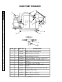
HAND PUMP STANDARD
1
2
4
5
6
7
3
10
9
8
11
6
VIEW A-A
A
A
ITEM QTY. PART NO. DESCRIPTION
1 1 251407 HAND PUMP WITH HANDLE
2 1 030282 NIPPLE, 1/4" x 1-1/2" LG.
3 1 226063 ELBOW, 90 DEG. 1/4 F-F
4 1 226948-09 HOSE ASSEMBLY H.P. 1/4" x 18-1/2 LG.
5 1 251852
FITTING STRAIHGT, 3/8 M x 1/4 F
SWIVEL
6 1 251851 TEE 3/8 M - 3/8 F SWIVEL
7 1 228151
FITTING STRAIGHT, 3/8 M x 3/8 F
SWIVEL
8 2 251853 ELBOW, 90 DEG. 1/4" M x 3/8" PUT ON
9 2 251854 CLAMP, GEAR TYPE
10 1 251856 HOSE, 3/8" L.P. x 20" LG.
11 1 251850 VALVE, NEEDLE 3/8" M - F

11921 Slauson Ave. Santa Fe Springs, CA. 90670 (800) 227-4116 FAX (888) 771-7713
PAGE 9
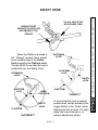
SAFETY HOOK
OIL ALL HOLES THE
ROD PASSES THRU
GREASE FRONT
SURFACE OF HOOK USE
AUTOMOBILE TYPE
GREASE
When the Platform is raised to
full Stowed position, there should
be an audible snap of the Safety
Hook engaging the Platform Loop.
Visually check to see that the loop is
positioned over the Safety Hook.
EXTENSION
PLATE
PLATFORM
LOOP
PLATFORM
SAFETY
HOOK
EXTENSION
PLATE
PLATFORM
LOOP
PLATFORM
SAFETY
HOOK
INCORRECT
CORRECT
BEND
DIRECTION
To insure that the Hook is seated
as described, test by activating the
Toggle Switch in the Down mode.
Gate should not go down. If it does,
adjust the loop as shown in, to
achieve adjustment shown.

11921 Slauson Ave. Santa Fe Springs, CA. 90670 (800) 227-4116 FAX (888) 771-7713
PAGE 10
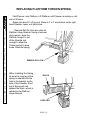
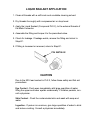
REPLACING PLATFORM TORSION SPRING
Fold Flipover onto Platform. Lift Platform until Flipover is resting on roll-
ers on lift arms.
Raise unit about 6 off ground. Place a 4 x 4 wood block under right
hand Shackle. Lower unit onto block.
Remove Roll Pin from pin collar on
Platform Hinge Bracket. Using a hammer
When installing the Spring,
be sure the long leg of the
spring is inserted into the
hole in the bracket on the
side of the Shackle. Short
leg of Spring will rest
against the block, which is
welded to the Platform
Hinge Bracket.
and a punch, drive the
Platform Hinge Pin out
of the Shackle just
enough to allow the
Torsion spring to drop
loose. Remove Spring.
REMOVE ROLL PIN
LONG LEG
BLOCK

11921 Slauson Ave. Santa Fe Springs, CA. 90670 (800) 227-4116 FAX (888) 771-7713
PAGE 11
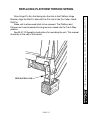
REPLACING PLATFORM TORSION SPRING
Drive Hinge Pin thru the Spring into the hole in the Platform Hinge
Bracket. Align the Roll Pin hole with the Pin hole in the Pin Collar. Install
Roll Pin.
Raise unit to allow wood block to be removed. The Platform and
Flipover can now be lowered to the ground or raised into the Tuk-A-Way
position.
See M-91-10 Operating Instructions for operating the unit. This manual
should be in the cab of the vehicle.
REPLACE ROLL PIN

11921 Slauson Ave. Santa Fe Springs, CA. 90670 (800) 227-4116 FAX (888) 771-7713
PAGE 12
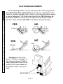
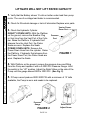
PLATFORM ADJUSTMENT
Before adjusting platform, remove and inspect each of the hinge pins for
wear. (Ref. Hinge Pin Location Sheet) If any are worn, replace them. Also
check for structural damage. Either condition could make the platform appear
in need of adjustment. The Platform should reflect the YES illustrations be-
low with the Platform as much as 2-1/2 higher than the extension plate or
floor bed. There should be NO SAG in the Platform as pictured below.
Shackles also rest on the
ground. If Platform is straight, no
shimming is required. If Platform
sags, appropriate shims must be
added to both sides. Shims can
be placed in either or both posi-
tions.
YES
YES
NO
NO
NO SAG
SAG
WELD SHIMS

11921 Slauson Ave. Santa Fe Springs, CA. 90670 (800) 227-4116 FAX (888) 771-7713
PAGE 13
10
2
3
4
5
6
8
9
7
1
10
7
3
5
6
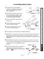
HINGE PIN LOCATION
Annually inspect both Hinge Pins and Bearings for excessive wear. If Pins
or Bearings are worn, replace with MAXON authorized parts. See Pin & Bear-
ing part list below for Part Numbers.
PINS
BEARINGS
ITEM QTY. PART NO. DESCRIPTION ITEM QTY. PART NO. DESCRIPTION
1 1 203405-09 PIN x 4" 8 1 260373 BEARING SELF LUBE 1 x 2"
2 1 203405-08 PIN x 5" 9 1 260369 BEARING SELF LUBE 1-1/8 x 2"
3 4 203405-06 PIN x 3-1/2" 10 8 260363 BEARING SELF LUBE 1 x 1-1/2"
4 1 203405-03 PIN x 11-1/4"
5 2 201633 PIN & COLLAR WELDMENT
6 2 203405-05 PIN x 3-1/4"
7 2 203405-07 PIN x 4-1/2"

11921 Slauson Ave. Santa Fe Springs, CA. 90670 (800) 227-4116 FAX (888) 771-7713
PAGE 14
1
2
1a
3
4
5
6
7
8
13
30b
16
9
10
11
12
14
3
5
17
18
20
18
23
24
25
22
21
36
19
17
27
26
20
28
23
30
30a
28
29
15
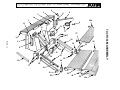
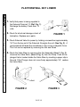
72-25/30LM ASSEMBLY

11921 Slauson Ave. Santa Fe Springs, CA. 90670 (800) 227-4116 FAX (888) 771-7713
PAGE 15
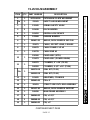
72-25/30LM ASSEMBLY
CONTINUED NEXT PAGE
ITEM QTY. PART NUMBER DESCRIPTION
1 1 207914-100 EXTENSION PLATE WELDMENT
1a 1 215341 SAFETY HOOK WELDMENT
2 1 215345 SPRING SAFETY HOOK
3 2 201638 DOCK BUMPER
4 1 203412 RENTAL LOCK DEVICE
5 2 222988 RUBBER BUMPER
6 1 201637-02 ANGLE, DOCK BUMPER SUP. R.H.
7 1 251871 CABLE, 32 FEET LONG, 2 GAUGE
8 7 050079 CABLE FRAME CLIP #2
9 1 226778 CABLE END #2
10 1
250100 PUMP ASSY. (STD.)
253473 PUMP ASSY. (POWER DOWN)
11 1
260372 CYLINDER, 3" x 10" (72-25)
260392 CYLINDER, 3-1/2" x 10" (72-30)
11a 1
260372-SK SEAL KIT (72-25)
260392-SK SEAL KIT (72-30)
12 1 201695 BREATHER, CYLINDER
13 1 203405-09 PIN x 4"
14 1 203411 STREET SIDE CNTL ROD ASSEMBLY
15 1 201637-01 ANGLE, DOCK BUMPER SUPPORT
16 1 260436 MAIN FRAME ASSEMBLY
17 4 260368-03 PIN, x 3-1/2"
18 2 260368-04 PIN, x 4-1/2"
19 1 260368-05 PIN, x 5"

11921 Slauson Ave. Santa Fe Springs, CA. 90670 (800) 227-4116 FAX (888) 771-7713
PAGE 16
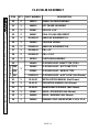
72-25/30LM ASSEMBLY
ITEM QTY. PART NUMBER DESCRIPTION
20 2 260370 PARALLEL ARM ASSEMBLY
21 1 260315 LIFT FRAME ASSEMBLY
22 2 221867 ROLLER x 3/4"
23 2 260367 PIN & COLLAR WELDMENT
24 1 201625-02 SHACKLE WELDMENT LH
25 1 201640 TORSION SPRING
26 1 201625-01 SHACKLE WELDMENT RH
27 1 260368-02 PIN, x 11"
28 2 203405-05 PIN, x 3-1/4"
29 1 207910 PLATFORM ASSEMBLY
30
1
201629 FLIPOVER ASSY. RAMP TYPE (STD.)
O
P
T
I
O
N
A
L
30a 201680 FLIPOVER ASSY. BUTT END TYPE
30b 213085 FLIPOVER ASSY. WEDGE TYPE
30c 253874-01 FLIPOVER ASSY. w/10" A.R.R. (Not Shown)
31 1 M-91-08 INSTALLATION MANUAL (Not Shown)
32 1 M-91-10 OPERATION MANUAL (Not Shown)
33 1 M-95-09 MAINTENANCE MANUAL (Not Shown)
34 1 251867 DECAL, OPERATING (Not Shown)
35 1 260008 DECAL, WARNING (Not Shown)
36 1 260369 BEARING SELF-LUBRICATING 1-1/8 x 2"LG.

11921 Slauson Ave. Santa Fe Springs, CA. 90670 (800) 227-4116 FAX (888) 771-7713
PAGE 17
GRAVITY DOWN SECTION
72-25 LM
72-30 LM
LIFT GATE SERIES

11921 Slauson Ave. Santa Fe Springs, CA. 90670 (800) 227-4116 FAX (888) 771-7713
PAGE 18
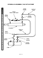
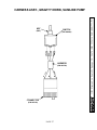
HYDRAULIC ASSEMBLY, OLD STYLE PUMP
251739
PRESS. COMP VALVE
202406
ELBOW
224370-07
HOSE
800183
BUSHING
CYLINDER
227004
ELBOW
228950
ELBOW
030304
NIPPLE
226948-16
HOSE
PUMP
800183
BUSHING
202406
ELBOW

11921 Slauson Ave. Santa Fe Springs, CA. 90670 (800) 227-4116 FAX (888) 771-7713
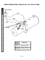
PAGE 19
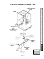
PUMP
PRESSURE
HOSE
PLASTIC RETURN
HOSE
PRESSURE
HOSE
(P/N 263714-01)
PLASTIC
RETURN HOSE
(P/N 263004-01)
ELBOW, BRASS
1/4NPT x 1/4TUBE
(P/N 202406)
BUSHING
3/8 x 1/4
(P/N 800183)
NIPPLE, 3/8 NPT
(P/N 030283)
ELBOW, BRASS
3/8NPT (M) x 3/8NPT (F)
(P/N 227004)
PRESS. CNTRL.
VALVE
(P/N 251739)
NOTE:
Do not use liquid sealant
on these fittings
HYDRAULIC ASSEMBLY, SLIMLINE PUMP
NOTE:
Apply Sealant to
connections per
inside back cover
of this manual

11921 Slauson Ave. Santa Fe Springs, CA. 90670 (800) 227-4116 FAX (888) 771-7713
PAGE 20
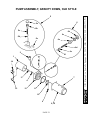
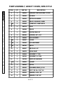
* NOT SHOWN
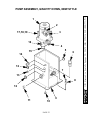
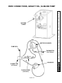
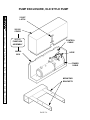
PUMP ASSEMBLY, GRAVITY DOWN, OLD STYLE
ITEM QTY. PART NUMBER DESCRIPTION
1 1 229272 MOTOR, 12 VOLTS DC
2 1 253353 VALVE, SOLENOID 2-WAY
*2a 1 226594 O-RING KIT, 2-WAY VALVE
3 1 229200 COUPLING
4 1 260261 OIL SEAL
5 1 251885 CHECK VALVE KIT
5a 1 260234 VALVE CAP
5b 1 260255 RETAINER
5c 1 260231 SPRING
5d 1 260257 STEEL BALL
5e 1 260256 SOCKET HEAD CAPSCREW
6 1 260229 RELIEF VALVE KIT
6a 1 260232 ADJUSTING SCREW
6b 1 260234 VALVE CAP
6c 1 260235 O-RING
6d 1 260231 SPRING
6e 1 260233 SPRING GUIDE
6f 1 260230 STEEL BALL
7 1 229193 FILLER/BREATHER CAP
8 1 251882 RESERVOIR, 3 QT.
9 1 260250 FILTER
10 1 260272 PUMP ASSEMBLY
11 1 251884 0-RING
12 1 260273 DRIVEPLATE ASSEMBLY 5"
13 1 262866 BUS BAR
14 1 262939 SOLENOID SWITCH
*15 4 229202 CAPSCREW, HEX. WASHER HD.
Page is loading ...
Page is loading ...
Page is loading ...
Page is loading ...
Page is loading ...
Page is loading ...
Page is loading ...
Page is loading ...
Page is loading ...
Page is loading ...
Page is loading ...
Page is loading ...
Page is loading ...
Page is loading ...
Page is loading ...
Page is loading ...
Page is loading ...
Page is loading ...
Page is loading ...
Page is loading ...
Page is loading ...
Page is loading ...
Page is loading ...
Page is loading ...
Page is loading ...
Page is loading ...
Page is loading ...
Page is loading ...
Page is loading ...
-
 1
1
-
 2
2
-
 3
3
-
 4
4
-
 5
5
-
 6
6
-
 7
7
-
 8
8
-
 9
9
-
 10
10
-
 11
11
-
 12
12
-
 13
13
-
 14
14
-
 15
15
-
 16
16
-
 17
17
-
 18
18
-
 19
19
-
 20
20
-
 21
21
-
 22
22
-
 23
23
-
 24
24
-
 25
25
-
 26
26
-
 27
27
-
 28
28
-
 29
29
-
 30
30
-
 31
31
-
 32
32
-
 33
33
-
 34
34
-
 35
35
-
 36
36
-
 37
37
-
 38
38
-
 39
39
-
 40
40
-
 41
41
-
 42
42
-
 43
43
-
 44
44
-
 45
45
-
 46
46
-
 47
47
-
 48
48
-
 49
49


Maxon 72 SERIES (Horizontal Pump M-95-09 Rev C March 1999) Maintenance Manual
- Type
- Maintenance Manual
- This manual is also suitable for
Ask a question and I''ll find the answer in the document
Finding information in a document is now easier with AI
Related papers
-
Maxon 72-150/TE-20 (Horizontal Pump) Operating instructions
-
Maxon TE-25/TE-30 Maintenance Manual
-
-
-
-
-
-
-
-
Other documents
-
E-Collar E-COLLAR BP-504 BarkLess Pro Rechargeable User manual
-
DKS Torsion Rod User manual
-
EZ-ACCESS TITAN S16 Installation guide
-
Balboa One Half Inch Air Control Operating instructions
-
OTC 5295 Operating instructions
-
-
 KennelMaster K6510CLBL/C User manual
-
-
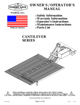 Tommy Gate CANTILEVER Series Owner's/Operator's Manual
-
Skil PP Series User manual

