Page is loading ...

Giles Enterprises, Inc.
An ISO9001 Registered Company
2750 Gunter Park Drive West • Montgomery, AL 36109 USA
Phone: (334) 272-1457 Fax: • (334) 272-3561 • Internet: www.gilesent.com
Service Hotline (Toll Free): 1-800-554-4537 (USA & Canada Only)
Form No. 63380 (Release date: 02/04/2005)(Revision Level: B)
RT-5
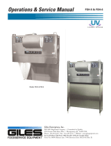
Operations & Service Manual
Model: RT-5
FOODSERVICE EQUIPMENT


LIMITED WARRANTY
• Subject to the terms and conditions of this Limited Warranty as herein stated, all Giles Enterprises,
Inc., Foodservice Equipment and parts purchased new from an authorized Giles Enterprises, Inc.,
representative are warranted as to defects in material or workmanship for a period of 12 months
from the date of installation, provided, however, that with regard to labor costs in connection with
this warranty, see below. All installations must be made by a qualified installing agency in accor-
dance with all applicable codes and/or regulations in the jurisdiction in which installed. Limited war-
ranty coverage is extended to the original owner only and is void if the unit is resold.
• During the Limited Warranty period, Giles Enterprises, Inc. will replace or recondition, at its factory,
any part or parts of this unit which Giles Enterprises, Inc. inspectors judge defective, provided the
unit has been subjected to normal usage, properly installed, operated and serviced. This Limited
Warranty does not cover cosmetic damage, and damage due to acts of God, accident, misuse, alter-
ation, negligence, abuse of the Giles Foodservice Equipment or the use of unorthodox repair meth-
ods. All parts replaced under this Limited Warranty carry only the unexpired term of this Limited
Warranty. Limited Warranty service may be furnished only by an authorized Giles Enterprises, Inc.,
representative.
• If Limited Warranty service is requested, Giles Enterprises, Inc., will send factory-authorized serv-
ice representatives to repair, recondition, replace or inspect units of its manufacture with such labor
being rendered without cost to owner for ninety (90) days from the date of installation. Otherwise,
service, including labor and transportation charges or other expenses, in connection with the
removal or installation of any part or parts supplied under this Limited Warranty, are specified on the
original sales contract between the purchaser and the authorized Giles Enterprises, Inc., represen-
tative.
• Giles Enterprises, Inc. reserves the right to change or improve its equipment and parts in any way
without obligation to alter such equipment or parts previously manufactured.
• Giles Enterprises, Inc. makes no further warranties, express or implied including implied warranties
of merchantability or fitness for a particular purpose, and has no other obligation or liability not
specifically stated herein.
• Repair or replacement as provided under this Limited Warranty is the exclusive remedy. Giles
Enterprises, Inc., shall not be liable for any incidental or consequential damages for breach of any
express or implied warranty on this product, except to the extent prohibited by applicable law. Any
implied warranty of merchantability or fitness for a particular purpose on this product is limited in
duration to the duration of this Limited Warranty.
• Used Giles Enterprises, Inc., Foodservice Equipment or parts or Giles Enterprises, Inc., Foodservice
Equipment or parts not purchased from an authorized Giles Enterprises, Inc., representative, carry
no warranties, express or implied.


iii
Model: RT-5
Safety . . . . . . . . . . . . . . . . . . . . . . . . . . . . . . . . . . . . . . . . . . . . . . . . . . . . . . . . v
Safety Overview . . . . . . . . . . . . . . . . . . . . . . . . . . . . . . . . . . . . . . . . . . . . . . . . . . . . . . . . . . . . . . . . . . . . v
Specific Safety Precautions . . . . . . . . . . . . . . . . . . . . . . . . . . . . . . . . . . . . . . . . . . . . . . . . . . . . . . . . . . . vi
1. Introduction . . . . . . . . . . . . . . . . . . . . . . . . . . . . . . . . . . . . . . . . . . . . . . 1
1-01. Construction . . . . . . . . . . . . . . . . . . . . . . . . . . . . . . . . . . . . . . . . . . . . . . . . . . . . . . . . . . . . . . 1
1-02. Standard Features. . . . . . . . . . . . . . . . . . . . . . . . . . . . . . . . . . . . . . . . . . . . . . . . . . . . . . . . . . 1
1-03. Specifications . . . . . . . . . . . . . . . . . . . . . . . . . . . . . . . . . . . . . . . . . . . . . . . . . . . . . . . . . . . . . 2
1-03.1. Overall Dimensions for RT-5 . . . . . . . . . . . . . . . . . . . . . . . . . . . . . . . . . . . . . . . . . . . . . . . . . . 2
1-03.2. Regulatory Listings . . . . . . . . . . . . . . . . . . . . . . . . . . . . . . . . . . . . . . . . . . . . . . . . . . . . . . . . . 3
1-03.3. Unit Weights . . . . . . . . . . . . . . . . . . . . . . . . . . . . . . . . . . . . . . . . . . . . . . . . . . . . . . . . . . . . . . 3
1-03.4. Shipping Specifications (Crated) . . . . . . . . . . . . . . . . . . . . . . . . . . . . . . . . . . . . . . . . . . . . . . . 3
1-04. Product Capacity. . . . . . . . . . . . . . . . . . . . . . . . . . . . . . . . . . . . . . . . . . . . . . . . . . . . . . . . . . . 3
2. Installation . . . . . . . . . . . . . . . . . . . . . . . . . . . . . . . . . . . . . . . . . . . . . . . 5
2-01. Unpacking . . . . . . . . . . . . . . . . . . . . . . . . . . . . . . . . . . . . . . . . . . . . . . . . . . . . . . . . . . . . . . . . 5
2-02. Location and Clearances. . . . . . . . . . . . . . . . . . . . . . . . . . . . . . . . . . . . . . . . . . . . . . . . . . . . . 6
2-03. Leg Installation . . . . . . . . . . . . . . . . . . . . . . . . . . . . . . . . . . . . . . . . . . . . . . . . . . . . . . . . . . . . 7
2-04. Table or Counter Installation . . . . . . . . . . . . . . . . . . . . . . . . . . . . . . . . . . . . . . . . . . . . . . . . . . 8
2-05. Electrical Requirements . . . . . . . . . . . . . . . . . . . . . . . . . . . . . . . . . . . . . . . . . . . . . . . . . . . . . 9
2-05.1. Electrical Specifications . . . . . . . . . . . . . . . . . . . . . . . . . . . . . . . . . . . . . . . . . . . . . . . . . . . . . 9
2-05.2. Electrical Connections. . . . . . . . . . . . . . . . . . . . . . . . . . . . . . . . . . . . . . . . . . . . . . . . . . . . . . 10
3. Overview . . . . . . . . . . . . . . . . . . . . . . . . . . . . . . . . . . . . . . . . . . . . . . . 13
3-01. Components . . . . . . . . . . . . . . . . . . . . . . . . . . . . . . . . . . . . . . . . . . . . . . . . . . . . . . . . . . . . . 14
3-02. Accessories. . . . . . . . . . . . . . . . . . . . . . . . . . . . . . . . . . . . . . . . . . . . . . . . . . . . . . . . . . . . . . 16
4. Operation . . . . . . . . . . . . . . . . . . . . . . . . . . . . . . . . . . . . . . . . . . . . . . . 17
4-01. Cooking Controller buttons and functions . . . . . . . . . . . . . . . . . . . . . . . . . . . . . . . . . . . . . . 18
4-02. Setting and running a Manual Menu . . . . . . . . . . . . . . . . . . . . . . . . . . . . . . . . . . . . . . . . . . 20
4-03. Programming a Programmed Menu . . . . . . . . . . . . . . . . . . . . . . . . . . . . . . . . . . . . . . . . . . . 22
4-04. Running a Programmed Menu . . . . . . . . . . . . . . . . . . . . . . . . . . . . . . . . . . . . . . . . . . . . . . . 23
4-05. Cancelling a Manual or Programmed Menu . . . . . . . . . . . . . . . . . . . . . . . . . . . . . . . . . . . . . 24
4-06. Viewing actual temperature in Rotisserie . . . . . . . . . . . . . . . . . . . . . . . . . . . . . . . . . . . . . . . 24
4-07. Using the Hand-Held Temperature Probe . . . . . . . . . . . . . . . . . . . . . . . . . . . . . . . . . . . . . . . 25
4-08. Spit installation . . . . . . . . . . . . . . . . . . . . . . . . . . . . . . . . . . . . . . . . . . . . . . . . . . . . . . . . . . . 26
4-09. Basket installation. . . . . . . . . . . . . . . . . . . . . . . . . . . . . . . . . . . . . . . . . . . . . . . . . . . . . . . . . 27
4-10. Spit removal . . . . . . . . . . . . . . . . . . . . . . . . . . . . . . . . . . . . . . . . . . . . . . . . . . . . . . . . . . . . . 28
4-11. Basket removal . . . . . . . . . . . . . . . . . . . . . . . . . . . . . . . . . . . . . . . . . . . . . . . . . . . . . . . . . . . 29
4-12. Spit Wheel Assembly removal . . . . . . . . . . . . . . . . . . . . . . . . . . . . . . . . . . . . . . . . . . . . . . . 30
4-13. Spit Wheel Assembly installation . . . . . . . . . . . . . . . . . . . . . . . . . . . . . . . . . . . . . . . . . . . . . 31
4-14. Normal Shut-Down . . . . . . . . . . . . . . . . . . . . . . . . . . . . . . . . . . . . . . . . . . . . . . . . . . . . . . . . 32
4-15. Emergency Shut-Down. . . . . . . . . . . . . . . . . . . . . . . . . . . . . . . . . . . . . . . . . . . . . . . . . . . . . 32
4-16. Recipes . . . . . . . . . . . . . . . . . . . . . . . . . . . . . . . . . . . . . . . . . . . . . . . . . . . . . . . . . . . . . . . . . 33
Table Of Contents

iv
Model: RT-5 Table Of Contents
5. Cleaning . . . . . . . . . . . . . . . . . . . . . . . . . . . . . . . . . . . . . . . . . . . . . . . . 35
5-01. Cleaning the Inner Cabinet . . . . . . . . . . . . . . . . . . . . . . . . . . . . . . . . . . . . . . . . . . . . . . . . . . 35
5-02. Cleaning the Outer Cabinet . . . . . . . . . . . . . . . . . . . . . . . . . . . . . . . . . . . . . . . . . . . . . . . . . 36
5-03. Cleaning the Glass Doors . . . . . . . . . . . . . . . . . . . . . . . . . . . . . . . . . . . . . . . . . . . . . . . . . . . 37
6. Troubleshooting . . . . . . . . . . . . . . . . . . . . . . . . . . . . . . . . . . . . . . . . . 39
6-01. Troubleshooting Procedures . . . . . . . . . . . . . . . . . . . . . . . . . . . . . . . . . . . . . . . . . . . . . . . . . 39
7. Parts List . . . . . . . . . . . . . . . . . . . . . . . . . . . . . . . . . . . . . . . . . . . . . . . 43
7–01. Parts Ordering and Service Information . . . . . . . . . . . . . . . . . . . . . . . . . . . . . . . . . . . . . . . . 43
7-02. Quartz Light Replacement . . . . . . . . . . . . . . . . . . . . . . . . . . . . . . . . . . . . . . . . . . . . . . . . . . 44
7-03. Fuse Replacement . . . . . . . . . . . . . . . . . . . . . . . . . . . . . . . . . . . . . . . . . . . . . . . . . . . . . . . . 44
7-04. Spit Wheel Assembly . . . . . . . . . . . . . . . . . . . . . . . . . . . . . . . . . . . . . . . . . . . . . . . . . . . . . . 46
7-05. Spit Wheel Support Replacement . . . . . . . . . . . . . . . . . . . . . . . . . . . . . . . . . . . . . . . . . . . . 46
7-06. Drive Motor Replacement . . . . . . . . . . . . . . . . . . . . . . . . . . . . . . . . . . . . . . . . . . . . . . . . . . 48
7-07. Drive Motor Assembly . . . . . . . . . . . . . . . . . . . . . . . . . . . . . . . . . . . . . . . . . . . . . . . . . . . . . 48
7-08. Element and Probe Replacement. . . . . . . . . . . . . . . . . . . . . . . . . . . . . . . . . . . . . . . . . . . . . 50
7-09. Blower Replacement . . . . . . . . . . . . . . . . . . . . . . . . . . . . . . . . . . . . . . . . . . . . . . . . . . . . . . 52
7-10. Component Replacement. . . . . . . . . . . . . . . . . . . . . . . . . . . . . . . . . . . . . . . . . . . . . . . . . . . 54
7-11. Controller Assembly . . . . . . . . . . . . . . . . . . . . . . . . . . . . . . . . . . . . . . . . . . . . . . . . . . . . . . . 54
7-12. Door Replacement . . . . . . . . . . . . . . . . . . . . . . . . . . . . . . . . . . . . . . . . . . . . . . . . . . . . . . . . 56
8. Wiring Diagram . . . . . . . . . . . . . . . . . . . . . . . . . . . . . . . . . . . . . . . . . . 59
8-01. Wiring Diagram RT-5 208-240/60/1. . . . . . . . . . . . . . . . . . . . . . . . . . . . . . . . . . . . . . . . . . . . 60
8-02. Wiring Diagram RT-5 208-240/60/3. . . . . . . . . . . . . . . . . . . . . . . . . . . . . . . . . . . . . . . . . . . . 62
8-03. Wiring Diagram RT-5 230/50/1 . . . . . . . . . . . . . . . . . . . . . . . . . . . . . . . . . . . . . . . . . . . . . . . 64
8-04. Wiring Diagram RT-5 380/50/3 . . . . . . . . . . . . . . . . . . . . . . . . . . . . . . . . . . . . . . . . . . . . . . . 66
8-05. Wiring Diagram RT-5 415/50/3 . . . . . . . . . . . . . . . . . . . . . . . . . . . . . . . . . . . . . . . . . . . . . . . 68

v
Model: RT-5Safety
Safety Overview
Safety
The instructions contained in this manual have been prepared to assist you in learning the proper proce-
dures for installing and servicing your unit.
Throughout this manual, safety precautions are identified through the use of the safety alert symbol and
three signal words: DANGER, WARNING, and CAUTION. All safety alert information precedes the
step(s) to which they apply. Suggested, recommended, or other noteworthy information is identified
through the use of NOTES. Additionally, certain words are used to indicate a specific meaning or to add
emphasis.
The following words are used as indicated throughout the manual:
Shall: understood to be mandatory.
Should: understood to be advisory.
May: understood to be permissive.
Will: indicates a future event/condition to occur.
or
(Safety Alert Symbol)
Used in conjunction with signal words (DANGER, WARNING, or CAUTION) to alert you of potential per-
sonal injury hazards, immediately preceding precautionary measures that pertain to subsequent step(s).
Obey all safety messages that follow this symbol to avoid possible injury or death. Failure to adhere to
safety precautions identified by the safety alert symbol may also void the warranty.
!!
• Indicates an imminently hazardous situation which, if not avoided, will result in death or serious injury.
Use of this is limited to the most extreme situations.
!
DANGER
•
Indicates a potentially hazardous situation which, if not avoided, could result in death or serious injury.
!
WARNING
• Indicates a potentially hazardous situation which, if not avoided, may result in minor or moderate injury.
Also used to alert against unsafe practices.
!
CAUTION
• When used without the safety alert symbol, CAUTION indicates a potentially hazardous situation
which, if not avoided, may result in equipment/property damage, and void the warranty.
CAUTION
NOTE:
•Identifies suggested, recommended, or other noteworthy information.

vi
Model: RT-5 Safety
Specific Safety Precautions
For your safety, please observe the following precautions when operating or servicing the Giles Rotisserie
Model RT-5. Read the following important safety information to avoid personal injury and/or damage to
the equipment.
• Always disconnect the source of the main power before removing any service covers.
•
Failure to comply with these DANGER notices will result in death or serious injury, equipment/property
damage, and void the warranty.
!
DANGER
• DO NOT use or store gasoline or other flammable liquids or vapors in the vicinity of this or any other
appliance!
• Consult a qualified electrician to ensure all electrical specifications have been met and the unit is prop-
erly grounded.
• Before installing or servicing this equipment, read the contents of this manual thoroughly.
• Improper installation, adjustment, alteration, service or maintenance could result in death or serious
injury, equipment/property damage, and void the warranty.
• Exercise care when lifting or moving the unit. For unit weights see Section 1-03.3.
• Exercise care when removing the wooden crate from around the unit.
• DO NOT CLEAN OR TOUCH the quartz lights located in top of the RT-5 doors.
• DO NOT CLEAN GLASS WHEN HOT! Clean glass with approved cleaner, do not use abrasive on
glass!
• Failure to comply with these WARNING notices could result in death or serious injury and
equipment/property damage.
!
WARNING

vii
Model: RT-5Safety
• Do not operate the RT-5 unless you fully understand all it’s components and their intended functions.
• The electronic components of the Control Panel are impact-sensitive. Exercise care around the Control
Panel to maintain proper operation.
• During cleaning of unit.
•• DO NOT steam clean.
•• DO NOT use products containing chlorine.
•• DO NOT use abrasive products, steel wool or scouring pads.
•• DO NOT USE OVEN CLEANER.
• DO NOT CLEAN OR TOUCH the quartz lights located in top of the RT-5 doors.
• Failure to comply with these CAUTION notices may result in equipment/property damage and void the
warranty.
CAUTION
NOTE:
•
If the Shipping Crate is damaged, immediately inspect the unit and notify the carrier of any damage to
the unit.
• To aid the electrician, an electrical wiring diagram is contained in this manual. Refer to the wiring dia-
gram during installation or servicing.
• Comply with all appropriate state and/or local heath regulations regarding the cleaning and sanitation of
equipment.
• For difficult to clean areas, a mild biodegradable nontoxic degreaser (such as Clear Magic or Simple
Green) may be used.
• Always ensure the unit is electrically grounded and installed in accordance with local codes, or in the
absence of local codes, in accordance with the National Electrical Code ANSI/NFPA No. 70-1984.

viii
Model: RT-5 Safety
Notes:

1
Model: RT-5Introduction
Congratulations on the purchase of your new Giles Rotisserie Model RT-5, manufactured by Giles
Enterprises, Inc., Montgomery, Alabama (USA).
To help protect your investment in this equipment, we recommend taking a few moments to familiarize
yourself with the installation, cleaning and maintenance procedures contained in this manual. Read these
instructions before installation and use. Adherence to these recommended procedures minimizes the
potential for costly "down-time" and equipment repairs. Please retain this manual for future reference.
Control Panel
• Controls are functional, easy to operate.
Temperature Controls
• Adjustable control up to 420ºF (215.5ºC).
• 10 programmable menus.
Doors
• Curved glass provides panoramic view of product.
• Both front and rear doors provide easy access for loading and cleaning.
1. Introduction
1-01. Construction
1-02. Standard Features
The RT-5, is constructed of a stainless steel frame and uses tempered glass in the doors.

2
Model: RT-5 Introduction
1-03. Specifications
1-03.1. Overall Dimensions for RT-5
INCHES [MILLIMETERS]
The following sections give various specifications of the RT-5.
Operator-side Door
Customer-side Door

3
Model: RT-5Introduction
1-03.2. Regulatory Listings
UL (US and Canada)
NSF
CE
Unit Crated Weight
Uncrated Weight
(without product)
RT-5 314 lbs [142.4 kg] 209 lbs [94.8 kg]
1-03.3. Unit Weights
1-03.4. Shipping Specifications (Crated)
Model
Net Weight Crated Size Volume
Lbs Kg
Length Width Height
Cubic
Feet
Cubic
Meters
In mm In mm In mm
RT-5 314 142.4 54 1371.6 36 914.4 42 1066 47.25 1.338
1-04. Product Capacity
Product Weight (lb) Weight (kg) Quantity
Whole Chicken 2-1/2 to 2-3/4 1.13 to 1.24 20
Ribs 3 to 3-1/2 1.36 to 1.58 5
Roast 5 2.26 5

4
Model: RT-5 Introduction
Notes:

5
Model: RT-5Installation
2. Installation
This section provides a summary of procedures necessary to install your new Giles Rotisserie,
Model RT-5. Before installing or servicing this equipment, please read the contents of this manual
thoroughly. Following these procedures will help ensure a safe and proper installation.
Your unit should arrive packaged in a wooden crate, covered with plastic shipping wrap, and secured to a
wooden platform by means of high-tensile strength strapping. Perform the following steps to uncrate the
unit:
1. Position the packaged RT-5 in an area with sufficient room for unpacking.
2. Cut and remove the plastic shipping wrap and any high-tensile strength straps from the exterior of the
wooden crate.
3. Carefully use a hammer and pry bar to remove the wooden crate from around the unit.
4. Cut and remove the plastic shipping wrap and high-tensile strength strapping that secures the unit to
the wooden platform.
5. Before installing, check the unit for damage. If unit was damaged during shipment, notify the carrier
immediately and file a claim.
6. Carefully remove the unit from the wooden platform and place at the installation site.
7. Using wire cutters, cut all plastic ties holding Spits or Baskets and Spit Wheel Assembly in place.
2-01. Unpacking
NOTE:
• If the crate is damaged, immediately inspect the unit and notify the carrier of any damage to the unit.
•
Exercise care when lifting or moving the unit, please see Section 1-03.3 for unit weights.
• Exercise care when removing the wooden crate from around the unit.
!
CAUTION

6
Model: RT-5 Installation
1. Select a location with adequate space to properly operate and service the RT-5.
2. A minimum clearance of 4 inches from the side of the RT-5 to any obstruction is required for
adequate ventilation through the unit. See below for proper clearances.
3. Mount the RT-5 on a Table or Counter that is capable of safely bearing it’s weight
and the maximum weight of product to be placed in the unit for cooking.
4. Place the RT-5 with Customer-side Door facing the customer and the Operator-side Door facing the
operator.
2-02. Location and Clearances
• DO NOT install the unit next to combustible walls or materials. Failure to maintain safe distances may result in
combustion.
•DO NOT MODIFY, ALTER OR ADD ATTACHMENTS TO THIS EQUIPMENT.
!
WARNING
Inches [Millimeters]
Operator-side Door
Customer-side Door

7
Model: RT-5Installation
1. Fasten Legs and Leg Mounts to the unit. Ensure the Leg Mounts are diagonal to each other to
stabilize the unit. See below
2-03. Leg Installation
Leg Mount
Leg Mount

8
Model: RT-5 Installation
(3) Screws per mount (Screws
supplied by customer)
Leg Mount
Lower Leg Adjustment
1. Place the unit on an adequate table or counter. Ensure the table or counter can maintain the weight of
the unit with a full load of product.
2. Ensure the unit is level. To help level the unit rotate the lower part of the adjustable legs clockwise or
counter-clockwise.
3. Using screws appropriate to the table or counter (not supplied), fasten (2) Leg Mounts with (3) screws
per mount, into the table or counter.
2-04. Table or Counter Installation
• Ensure the Table or Counter can adequately maintain the weight of the unit (See Section 1.03.3
for unit weights) and the weight of the product being cooked.
!
WARNING

9
Model: RT-5Installation
2-05. Electrical Requirements
2-05.1. Electrical Specifications
• The unit must be adequately and properly grounded. Improper grounding may result in electrical
shock. Always refer to your local electrical code to ensure proper grounding of this or any other
electrical equipment. Always consult with an electrician or other qualified service person to ensure
breakers and wiring are of sufficient rating and gauge for the equipment being operated.
!
WARNING
Model Voltage Hz Phase Watts
AMPS
Circuit
Breaker
Required
(amps)
L1 L2 L3
RT-5 208 60 1 6,160 29.6 29.6 -- 40
RT-5 208 60 3 6,160 13.1 21.6 17.7 30
RT-5 240 60 1 6,160 25.6 25.6 -- 40
RT-5 240 60 3 6,160 11. 3 18.7 15.5 30
RT-5 230 50 3 6,160 11. 3 18.7 15.5 30
RT-5 380 50 3 6,160 9.0 4.4 13.4 20
RT-5 415 50 3 6,160 8.7 4.2 12.8 20
The following sections describe various electrical specifications and connections for the RT-5.
Please see the Serial Plate attached to the RT-5, for the proper Voltage, Hz, and Phase of the unit.

10
Model: RT-5 Installation
2-05.2. Electrical Connections
1. Install appropriate Circuit Breakers in Main Breaker Box. See Table 2-05.1.
2. Connect appropriate size Power Cable for the Voltage and Phase being used, to the Main Breaker.
Allow enough Power Cable so the unit can be moved for cleaning and servicing.
3. Remove the Side Cover and Probe Holders.
4. Fasten Cable or Conduit to the unit using customer supplied Cord Strain Relief or Cable Connector.
5. Connect Grounding Wire to the unit’s Ground Lug.
6. Connect appropriate Power wires to the unit’s Contactor.
Main
Breakers
Power
Wires
Ground
Wire
Ground
Lug
Contactor
L1
L3 L2
L3 for 3 phase only
Side Cover
(Continued next page)
Probe Holders
/