Carrier 100GTN Specification
- Category
- Small kitchen appliances
- Type
- Specification

Controls, Start-Up, Operation,
Service, and Troubleshooting
SAFETY CONSIDERATIONS
Installing, starting up, and servicing this equipment can
be hazardous due to system pressures, electrical compo-
nents, and equipment location (roof, elevated structures, etc.).
Only trained, qualified installers and servicemechanics should
install, start up, and service this equipment.
When working on this equipment, observe precautions in
the literature, and on tags, stickers, and labels attached to the
equipment, and any other safety precautions that apply. Fol-
low all safety codes. Wear safety glasses and work gloves.
Use care in handling, rigging, and setting this equipment,
and in handling all electrical components.
Electrical shock can cause personal injury and death.
Shut off all power to this equipment during installation
and service. There may be more than one disconnect
switch. Tag all disconnect locations to alert others not
to restore power until work is completed.
This unit uses a microprocessor-based electronic con-
trol system. Do not use jumpers or other tools to short
out components, or to bypass or otherwise depart from
recommended procedures. Any short-to-ground of the
control board or accompanying wiring may destroy the
electronic modules or electrical components.
To prevent potential damage to heat exchanger tubes al-
ways run fluid through heat exchangers when adding or
removing refrigerant charge. Use appropriate brine so-
lutions in cooler and condenser fluid loops to prevent
the freezing of heat exchangers when the equipment is
exposed to temperatures below 32 F (0° C).
DO NOT VENT refrigerant relief valves within a build-
ing. Outlet from relief valves must be vented outdoors
in accordance with the latest edition of ANSI/ASHRAE
(American National Standards Institute/American Soci-
ety of Heating, Refrigeration and Air Conditioning En-
gineers) 15 (Safety Code for Mechanical Refrigeration).
The accumulation of refrigerant in an enclosed space
can displace oxygen and cause asphyxiation. Provide ad-
equate ventilation in enclosed or low overhead areas.
Inhalation of high concentrations of vapor is harmful
and may cause heart irregularities, unconsciousness or
death. Misuse can be fatal. Vapor is heavier than air and
reduces the amount of oxygen available for breathing.
Product causes eye and skin irritation. Decomposition
products are hazardous.
DO NOT attempt to unbraze factory joints when ser-
vicing this equipment. Compressor oil is flammable and
there is no way to detect how much oil may be in any
of the refrigerant lines. Cut lines with a tubing cutter as
required when performing service. Use a pan to catch
any oil that may come out of the lines and as a gage for
how much oil to add to system. DO NOT re-use com-
pressor oil.
CONTENTS
Page
SAFETY CONSIDERATIONS ...................1
GENERAL ...................................2
INTRODUCTION ..............................2
MAJOR SYSTEM COMPONENTS ............3-10
General ......................................3
Main Base Board (MBB) ......................3
Expansion Valve (EXV) Board .................3
Compressor Expansion Board (CXB) ..........3
Scrolling Marquee Display ....................3
Energy Management Module (EMM) ...........3
Enable/Off/Remote Contact Switch ............3
Emergency On/Off Switch ....................3
Reset Button ................................3
Board Address ...............................3
Control Module Communication ..............3
Carrier Comfort Network Interface ............3
OPERATING DATA .........................11-46
Sensors ....................................11
• T1 — COOLER LEAVING FLUID SENSOR
• T2 — COOLER ENTERING FLUID SENSOR
• T3,T4 — SATURATED CONDENSING
TEMPERATURE SENSORS
• T5,T6 — COOLER SUCTION TEMPERATURE
SENSORS
• T7,T8 — COMPRESSOR SUCTION GAS
TEMPERATURE SENSORS
• T9 — OUTDOOR-AIR TEMPERATURE SENSOR
• T10 — REMOTE SPACE TEMPERATURE SENSOR
Thermostatic Expansion Valves (TXV) ........15
Compressor Protection Control System
(CPCS) or Control Relay (CR) ..............15
Compressor Current Protection Board
(CGF) and Control Relay (CR) ..............15
Electronic Expansion Valve (EXV) ............16
Energy Management Module .................16
Capacity Control ............................16
• MINUTES LEFT FOR START
• MINUTES OFF TIME
• LOADING SEQUENCE
• LEAD/LAG DETERMINATION
• CAPACITY SEQUENCE DETERMINATION
• CAPACITY CONTROL OVERRIDES
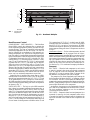
30GTN,GTR040-420
Air-Cooled Reciprocating Liquid Chillers
with
ComfortLink™
Controls
50/60 Hz
Manufacturer reserves the right to discontinue, or change at any time, specifications or designs without notice and without incurring obligations.
Book 2
Tab 5c
PC 903 Catalog No. 533-099 Printed in U.S.A. Form 30GTN-1T Pg 1 5-99 Replaces: New

CONTENTS (cont)
Page
Head Pressure Control ......................27
• COMFORTLINK™ UNITS (With EXV)
• UNITS WITH TXV
Pumpout ...................................27
• EXV UNITS
• TXV UNITS
Marquee Display Usage .....................29
Service Test ................................29
Configuring and Operating Dual Chiller
Control ...................................29
Temperature Reset ..........................43
Demand Limit ...............................45
• DEMAND LIMIT (2-Stage Switch Controlled)
• EXTERNALLY POWERED DEMAND LIMIT
(4 to 20 mA Controlled)
• DEMAND LIMIT (CCN Loadshed Controlled)
TROUBLESHOOTING ......................46-51
Compressor Protection Control System
(CPCS) Board .............................46
Compressor Ground Current (CGC) Board
(30GTN,R130-210, 230A-315A, and
330A/B-420A/B) ...........................46
EXV Troubleshooting ........................46
• STEP 1 − CHECK PROCESSOR EXV OUTPUTS
• STEP 2 — CHECK EXV WIRING
• STEP 3 — CHECK RESISTANCE OF EXV MOTOR
WINDINGS
• STEP 4 — CHECK THERMISTORS THAT
CONTROL EXV
• STEP 5 — CHECK OPERATION OF THE EXV
Alarms and Alerts ...........................47
SERVICE ..................................52-64
Electronic Components .....................52
Compressors ...............................52
• COMPRESSOR REMOVAL
• OIL CHARGE
Cooler ......................................52
• COOLER REMOVAL
• REPLACING COOLER
• SERVICING THE COOLER
Condenser Coils ............................55
Condenser Fans ............................55
Refrigerant Feed Components ...............56
• ELECTRONIC EXPANSION VALVE (EXV)
• MOISTURE-LIQUID INDICATOR
• FILTER DRIER
• LIQUID LINE SOLENOID VALVE
• LIQUID LINE SERVICE VALVE
Thermistors ................................57
• LOCATION
• REPLACING THERMISTOR T2
• REPLACING THERMISTORS T1,T5,T6,T7, AND T8
• THERMISTORS T3 AND T4
• THERMISTOR/TEMPERATURE SENSOR CHECK
Safety Devices ..............................63
• COMPRESSOR PROTECTION
• LOW OIL PRESSURE PROTECTION
• CRANKCASE HEATERS
• COOLER PROTECTION
Relief Devices ..............................64
• HIGH-SIDE PROTECTION
• LOW-SIDE PROTECTION
• PRESSURE RELIEF VALVES
Other Safeties ..............................64
PRE-START-UP .............................64
System Check ..............................64
START-UP AND OPERATION ...............65,66
Actual Start-Up .............................65
Page
Operating Limitations .......................65
• TEMPERATURES
• VOLTAGE
• MINIMUM FLUID LOOP VOLUME
• FLOW RATE REQUIREMENTS
Operation Sequence ........................66
APPENDIX A — CCN TABLES ..............67-74
START-UP CHECKLIST ..............CL-1 to CL-8
GENERAL
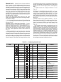
Unit sizes 230-420 are modular units which are shipped
as separate sections (modules A and B). Installation instruc-
tions specific to these units are shipped inside the individual
modules. See Table 1 for a listing of unit sizes and modular
combinations. For modules 230B-315B, follow all general
instructions as noted for unit sizes 080-110. For all remain-
ing modules, follow instructions for unit sizes 130-210.
INTRODUCTION
This publication contains Start-Up, Service, Controls, Op-
eration, and Troubleshootinginformation for the 30GTN,R040-
420 liquid chillers with ComfortLink controls.
The 30GTN,R chillers are equipped with electronic ex-
pansion valves (EXVs) or, on size 040-110 FIOP (factory-
installed option) units, conventional thermostatic expansion
valves (TXVs). The size 040-110 FIOP chillers are also
equipped with liquid line solenoid valves (LLSV).
NOTE: TXVs are not available on modular units.
Differences in operations and controls between standard
and 040-110 FIOP units are noted in appropriate sections in
this publication. Refer to the Installation Instructions and the
Wiring Diagrams for the appropriate unit for further details.
This unit uses a microprocessor-based electronic con-
trol system. Do not use jumpers or other tools to short
out or bypass components or otherwise depart from
recommended procedures. Any short-to-ground of the
control board or accompanying wiring may destroy the
board or electrical component.
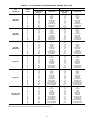
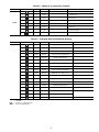
Table 1 — Unit Sizes and Modular Combinations
UNIT MODEL
30GTN,R
NOMINAL
TONS
SECTION A
UNIT 30GTN,R
SECTION B
UNIT 30GTN,R
40 40 — —
45 45 — —
50 50 — —
60 60 — —
70 70 — —
80 80 — —
90 90 — —
100 100 — —
110 110 — —
130 125 — —
150 145 — —
170 160 — —
190 180 — —
210 200 — —
230 220 150 080
245 230 150 090
255 240 150 100
270 260 170 100
290 280 190 110
315 300 210 110
330 325 170 170
360 350 190 190/170*
390 380 210 190
420 400 210 210
*60 Hz units/50 Hz units.
2

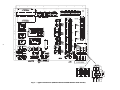
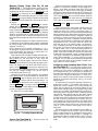
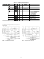
MAJOR SYSTEM COMPONENTS
General —
The 30GTN,R air-cooled reciprocating chill-
ers contain the ComfortLink™ electronic control system that
controls and monitors all operations of the chiller.
The control system is composed of several components as
listed in the sections below. See Fig. 1 for typical control
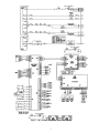
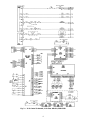
box drawing. See Fig. 2-4 for control schematics.
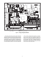
Main Base Board (MBB) — See Fig. 5. The MBB is
the heart of the ComfortLink control system. It contains the
major portion of operating software and controls the opera-
tion of the machine. The MBB continuously monitors input/
output channel information received from its inputs and from
all other modules. The MBB receives inputs from ther-
mistors T1-T6, T9, and T10. See Table 2. The MBB also
receives the feedback inputs from compressors A1, A2, B1
and B2, and other status switches. See Table 3. The MBB
also controls several outputs. Relay outputs controlled by the
MBB are shown in Table 4. Information is transmitted be-
tween modules via a 3-wire communication bus or LEN (Lo-
cal Equipment Network). The CCN (Carrier Comfort Net-
work) bus is also supported. Connections to both LEN and
CCN buses are made at TB3. See Fig. 5.
Expansion Valve (EXV) Board — The electronic
expansion valve (EXV) board receives inputs from ther-
mistors T7 and T8. See Table 2. The EXV board commu-
nicates with the MBB and directly controls the expansion
valves to maintain the correct compressor superheat.
CompressorExpansionBoard(CXB) — The com-
pressor expansion board (CXB) receives the feedback in-
puts from compressorsA3, B3 andA4. See Table 3. The CXB
board communicates the status to the MBB and controls the
outputs for these compressors. The CXB board can also be
used as an accessory to control up to two field-installed ac-
cessory unloaders on 080-110, 130 (60 Hz), and 230B-315B
sizes.
ScrollingMarquee Display — This device is the key-
pad interface used for accessing chiller information, reading
sensor values, and testing the chiller. The marquee display is
a 4-key, 4-character, 16-segment LED (light-emitting diode)
display. Eleven mode LEDs are located on the display as
well as an Alarm Status LED. See Marquee Display Usage
section on page 29 for further details.
Energy Management Module (EMM) — The EMM
module is available as a factory-installed option or as a field-
installed accessory. The EMM module receives 4 to 20 mA
inputs for the temperature reset, cooling set point reset and
demand limit functions. The EMM module also receives the
switch inputs for the field-installed 2-stage demand limit and
ice done functions. The EMM module communicates the sta-
tus of all inputs with the MBB, and the MBB adjusts the
control point, capacity limit, and other functions according
to the inputs received.
Enable/Off/RemoteContactSwitch — The Enable/
Off/Remote Contact switch is a 3-position switch used to
control the chiller. When switched to the Enable position the
chiller is under its own control. Move the switch to the Off
position to shut the chiller down. Move the switch to the
Remote Contact position and a field installed dry contact can
be used to start the chiller. The contacts must be rated for
dry circuit application capable of handlinga5vdc,1to
20 mA load. In the Enable and Remote Contact (dry con-
tacts closed) positions, the chiller is allowed to operate and
respond to the scheduling configuration, CCN configuration
and set point data. See Fig. 6.
Emergency On/Off Switch — The Emergency On/
Off switch should only be used when it is required to shut
the chiller off immediately. Power to the MBB, EMM, CXB,
and marquee display is interrupted when this switch is off
and all outputs from these modules will be turned off. The
EXV board is powered separately, but expansion valves will
be closed as a result of the loss of communication with the
MBB. There is no pumpout cycle when this switch is used.
See Fig. 6.
Reset Button — A reset button is located on the fuse/
circuit breaker panel for unit sizes 130-210 and associated
modules. The reset button must be pressed to reset either
Circuit Ground Fault board in the event of a trip.
BoardAddresses — The Main Base Board (MBB) has
a 3-position Instance jumper that must be set to ‘1.’All other
boards have 4-position DIP switches. All switches are set to
‘On’ for all boards.
Control Module Communication
RED LED — Proper operation of the control boards can be
visually checked by looking at the red status LEDs (light-
emitting diodes). When operating correctly, the red status LEDs
should be blinking in unison at a rate of once every 2 sec-
onds. If the red LEDs are not blinking in unison, verify that
correct power is being supplied to all modules. Be sure that
the Main Base Board (MBB) is supplied with the current
software. If necessary, reload current software. If the prob-
lem still persists, replace the MBB. A board LED that is lit
continuously or blinking at a rate of once per second or faster
indicates that the board should be replaced.
GREEN LED — The MBB has one green LED. The Local
Equipment Network (LEN) LED should always be blinking
whenever power is on. All other boards have a LEN LED
which should be blinking whenever power is on. Check LEN
connections for potential communication errors at the board
J3 and/or J4 connectors. Communication between modules
is accomplished by a 3-wire sensor bus. These 3 wires run
in parallel from module to module. The J4 connector on the
MBB provides both power and communication directly to
the marquee display only.
YELLOW LED — The MBB has one yellow LED. The
Carrier Comfort Network (CCN) LED will blink during times
of network communication.
Carrier Comfort Network (CCN) Interface — The
30GTN,R chiller units can be connected to the CCN if de-
sired.The communication bus wiring is a shielded, 3-conductor
cable with drain wire and is supplied and installed in the
field. The system elements are connected to the communi-
cation bus in a daisy chain arrangement. The positive pin of
each system element communication connector must be wired
to the positive pins of the system elements on either side of
it. This is also required for the negative and signal ground
pins of each system element. Wiring connections for CCN
should be made at TB3. Consult the CCN Contractor’s Manual
for further information.
NOTE: Conductors and drain wire must be 20 AWG (Amer-
ican Wire Gage) minimum stranded, tinned copper. In-
dividual conductors must be insulated with PVC, PVC/
nylon, vinyl, Teflon, or polyethylene.An aluminum/polyester
100% foil shield and an outer jacket of PVC, PVC/nylon,
chrome vinyl, or Teflon with a minimum operating tem-
perature range of −20 C to 60 C is required. Wire manu-
factured byAlpha (2413 or 5463),American (A22503), Belden
(8772), or Columbia (02525) meets the above mentioned
requirements.
3

It is important when connecting to a CCN communication
bus that a color coding scheme be used for the entire net-
work to simplify the installation. It is recommended that red
be used for the signal positive, black for the signal negative,
and white for the signal ground. Use a similar scheme for
cables containing different colored wires.
At each system element, the shields of its communication
bus cables must be tied together. If the communication bus
is entirely within one building, the resulting continuous shield
must be connected to a ground at one point only. If the com-
munication bus cable exits from one building and enters an-
other, the shields must be connected to grounds at the light-
ning suppressor in each building where the cable enters or
exits the building (one point per building only). To connect
the unit to the network:
1. Turn off power to the control box.
2. Cut the CCN wire and strip the ends of the red (+), white
(ground), and black (−) conductors. (Substitute appropri-
ate colors for different colored cables.)
3. Connect the red wire to (+) terminal on TB3 of the plug,
the white wire to COM terminal, and the black wire to
the (−) terminal.
4. The RJ14 CCN connector on TB3 can also be used, but
is only intended for temporary connection (for example,
a laptop computer running Service Tool).
IMPORTANT: A shorted CCN bus cable will prevent
some routines from running and may prevent the unit
from starting. If abnormal conditions occur, unplug the
connector. If conditions return to normal, check the CCN
connector and cable. Run new cable if necessary. A
short in one section of the bus can cause problems with
all system elements on the bus.
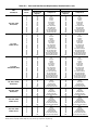
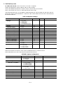
Table 2 — Thermistor Designations
THERMISTOR
NO.
PIN
CONNECTION
POINT
THERMISTOR INPUT
T1 J8-13,14 (MBB) Cooler Leaving Fluid
T2 J8-11,12 (MBB) Cooler Entering Fluid
T3 J8-21,22 (MBB)
Saturated Condensing
Temperature, Ckt A
T4 J8-15,16 (MBB)
Saturated Condensing
Temperature, Ckt B
T5 J8-24,25 (MBB)
Cooler Suction Temperature,
Ckt A (EXV Only)
T6 J8-18,19 (MBB)
Cooler Suction Temperature,
Ckt B (EXV Only)
T7 J5-11,12 (EXV)
Compressor Suction Gas
Temperature, Ckt A (EXV Only)
T8 J5-9,10 (EXV)
Compressor Suction Gas
Temperature, Ckt B (EXV Only)
T9 J8-7,8 (MBB)
Outdoor-Air Temperature Sensor
(Accessory)
T10 J8-5,6 (MBB)
Remote Space Temperature
Sensor (Accessory)
LEGEND
EXV — Electronic Expansion Valve
MBB — Main Base Board
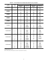
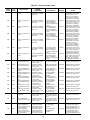
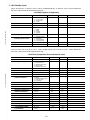
Table 3 — Status Switches
STATUS SWITCH
PIN
CONNECTION
POINT
040-060 (50 Hz)
040-070 (60 Hz)
070
(50 Hz)
080, 230B
090-110,
245B-315B
130
(60 Hz)
130 (50 Hz)
150, 230A-255A
170,190,
270A,290A,330A/B,
360A/B, 390B
210, 315A,
390A, 420A/B
Oil Pressure, Ckt B J7-1, 2 (MBB) Not Used* OPSB OPSB OPSB OPSB OPSB OPSB
Oil Pressure, Ckt A J7-3, 4 (MBB) Not Used* OPSA OPSA OPSA OPSA OPSA OPSA
Remote On/Off TB5-13, 14 Field-Installed Relay Closure
Compressor Fault
Signal, B3
J5-8, 12 (CXB) Not Used Not Used Not Used Not Used Not Used CR-B3 CR-B3
Compressor Fault
Signal, B2
J9-2, 12 (MBB) Not Used Not Used CPCS-B2 CR-B2 CR-B2 CR-B2 CR-B2
Compressor Fault
Signal, B1
J9-8, 12 (MBB) CR/CPCS-B1† CPCS-B1 CPCS-B1 CR-B1 CR-B1 CR-B1 CR-B1
Compressor Fault
Signal, A4
J5-5, 12 (CXB) Not Used Not Used Not Used Not Used Not Used Not Used CR-A4
Compressor Fault
Signal, A3
J5-11, 12 (CXB) Not Used Not Used Not Used Not Used CR-A3 CR-A3 CR-A3
Compressor Fault
Signal, A2
J9-5, 12 (MBB) Not Used CPCS-A2 CPCS-A2 CR-A2 CR-A2 CR-A2 CR-A2
Compressor Fault
Signal, A1
J9-11, 12 (MBB) CR/CPCS-A1† CPCS-A1 CPCS-A1 CR-A1 CR-A1 CR-A1 CR-A1
LEGEND
CPCS — Compressor Protection Control System
CR — Control Relay
CXB — Compressor Expansion Board
MBB — Main Base Board
OPS — Oil Pressure Switch, Circuit A or B
*The OPS can also be added as an accessory.
†The CPCS can be added as an accessory.
4

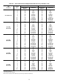
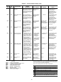
Table 4 — Output Relay
RELAY NO. DESCRIPTION
K0 (MBB)
Energize Compressor A1 and OFM1 (040-110*)
Energize Liquid Line Solenoid Valve for Ckt A (if used)
(040-110*)
Energize Compressor A1, OFM5, and OFM7 (130-210*)
K1 (MBB)
Energize Compressor B1 and OFM2 (040-110*)
Energize Liquid Line Solenoid Valve for Ckt B (if used)
(040-110*)
Energize Compressor B1, OFM6, and OFM8 (130-210*)
K2 (MBB)
Energize Unloader A1 (040-170*)
No Action (190-210*)
K3 (MBB)
Energize Unloader B1 (040-070†, 080-170*)
No Action (190,210*)
K4 (MBB)
No Action (040-060, 50 Hz; 040-070, 60 Hz)
Energize Compressor A2 (070, 50 Hz; 080-210*)
K5 (MBB)
No Action (040-080*)
Energize Compressor B2 (090-210*)
K6 (MBB) Alarm
K7 (MBB) Cooler Pump
K8 (MBB)
Energize First Stage of Condenser Fans:
040-050 — OFM3
060-110* — OFM3, OFM4
130 (60 Hz) — OFM1,OFM2
Energize First Stage of Ckt A Condenser Fans:
130 (50 Hz), 150,170* — OFM1
190,210* — OFM1,OFM11
K9 (MBB)
Energize First Stage of Condenser Fans:
040-050 — OFM4
060-090* — OFM5, OFM6
100,110* — OFM5,OFM6,OFM7,OFM8
130 (60 Hz) — OFM3,OFM4,OFM9,OFM10
Energize First Stage of Ckt B Condenser Fans:
130 (50 Hz), 150,170* — OFM2
190,210* — OFM2,OFM12
K10 (MBB) Hot Gas Bypass
K1 (CXB)
No Action (040-110*; 130, 60 Hz)
Energize Compressor A3 (130, 50 Hz; 150-210*)
K2 (CXB)
No Action (040-150*)
Energize Compressor B3 (170-210*)
K3 (CXB)
Energize Compressor A4 (210*)
Energize Accessory Unloader A2 (080-110*)
K4 (CXB) Energize Accessory Unloader B2 (080-110*)
K5 (CXB)
Energize Second Stage of Ckt A Condenser Fans:
130 (50 Hz), 150-210* — OFM3,OFM9
K6 (CXB)
Energize Second Stage of Ckt B Condenser Fans:
130 (50 Hz), 150-210* — OFM4,OFM10
LEGEND
OFM — Outdoor-Fan Motor
*And associated modular units.
†Field-installed accessory unloader.
LEGEND FOR FIG. 1-4
C—Compressor Contactor
CB — Circuit Breaker
CCN — Carrier Comfort Network
CGF — Compressor Ground Fault
CHT — Cooler Heater Thermostat
CKT — Circuit
CLHR — Cooler Heater Relay
CPCS — Compressor Protection and Control System
CWF — Chilled Water Flow Switch
CWP — Chilled Water Pump
CR — Control Relay
CXB — Compressor Expansion Board
EQUIP GND — Equipment Ground
FB — Fuse Block
FC — Fan Contactor
FCB — Fan Circuit Breaker
FIOP — Factory-Installed Option Package
EMM — Energy Management Module
EXV — Electronic Expansion Valve
FCB — Fan Circuit Breaker
HPS — High-Pressure Switch
LCS — Loss-of-Charge Switch
MBB — Main Base Board
NEC — National Electrical Code
OAT — Outdoor-Air Temperature
OPS — Oil Pressure Switch
PL — Plug
PW — Part Wind
SN — Sensor (Toroid)
SPT — Space Temperature
TRAN — Transformer
SW — Switch
TB — Terminal Block
TDR — Time Delay Relay
TXV — Thermostatic Expansion Valve
UL — Unloader
XL — Across-the-Line
5

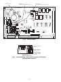
Fig.1—Typical Control Box (080-110 and Associated Modular Units Shown)
6

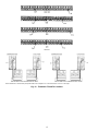
Fig.2—24VControl Schematic, Unit Sizes 040-070
7

Fig.3—24VControl Schematic, Unit Sizes 080-110, 230B-315B
8

Fig.4—24VControl Schematic, Unit Sizes 130-210, 230A-315A, 330A/B-420A/B
9

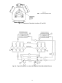
CEPL130346-01
STATUS
LEN
J1
J2
J4
J3
J5
J6
J7
J8
J9
J10
CCN
RED LED - STATUS GREEN LED -
LEN (LOCAL EQUIPMENT NETWORK)
YELLOW LED -
CCN (CARRIER COMFORT NETWORK)
Fig. 5 — Main Base Board
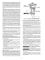
EMERGENCY ON/OFF
SWITCH
ENABLE/OFF/REMOTE
CONTACT SWITCH
RESET BUTTON
(30GTN,R130-210 AND
ASSOCIATED MODULES ONLY)
GFI-CONVENIENCE
OUTLET ACCESSORY
ON 208/230V 460 AND
575V ONLY
Fig. 6 — Enable/Off/Remote Contact Switch, Emergency On/Off Switch,
and Reset Button Locations
10

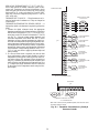
OPERATING DATA
Sensors —
The electronic control uses 4 to 10 ther-
mistors to sense temperatures for controlling chiller opera-
tion. See Table 2. These sensors are outlined below. See
Fig.7-10forthermistor locations. Thermistors T1-T9 are
5kVat 25 C (77 F) and are identical in temperature versus
resistance and voltage drop performance. Thermistor T10 is
a10kVat 25 C (77 F) and has a different temperature vs
resistance and voltage drop performance. See Thermistors
section on page 55 for temperature-resistance-voltage drop
characteristics.
T1 — COOLER LEAVING FLUID SENSOR — This ther-
mistor is located in the leaving fluid nozzle. The thermistor
probe is inserted into a friction-fit well. The sensor well is
located directly in the refrigerant path.
T2 — COOLER ENTERING FLUID SENSOR — This ther-
mistor is located in the cooler shell in the first baffle space
in close proximity to the cooler tube bundle.
T3, T4 — SATURATED CONDENSING TEMPERATURE
SENSORS — These 2 thermistors are clamped to the out-
side of a return bend of the condenser coils.
T5, T6 — COOLER SUCTION TEMPERATURE SEN-
SORS — These thermistors are located next to the refrig-
erant inlet in the cooler head, and are inserted into a friction-
fit well. The sensor well is located directly in the refrigerant
path. These thermistors are not used on units with TXVs.
T7, T8 — COMPRESSOR SUCTION GAS TEMPERA-
TURE SENSORS — These thermistors are located in the
lead compressor in each circuit in a suction passage after the
refrigerant has passed over the motor and is about to enter
the cylinders. These thermistors are inserted into friction-fit
wells. The sensor wells are located directly in the refrigerant
path. These thermistors are not used on units with TXVs.
T9 — OUTDOOR-AIR TEMPERATURE SENSOR — Sen-
sor T9 is an accessory sensor that is remotely mounted and
used for outdoor-air temperature reset.
LEGEND
EXV — Electronic Expansion Valve
*And associated modular units.
Fig. 7 — Cooler Thermistor Locations
040-110*
130-210*
11

040-070
080-110 AND ASSOCIATED MODULAR UNITS 130-210 AND ASSOCIATED MODULAR UNITS*
*When thermistor is viewed from perspective where the compressor is on the left and the cooler is on the right.
Fig. 8 — Thermistor T3 and T4 Locations
12

LEGEND
EXV — Electronic Expansion Valve
Fig. 9 — Compressor Thermistor Locations (T7 and T8)
Fig. 10 — Typical Thermistor Location (30GTN,R210, 315A, 390A, 420A/B Shown)
13

T10 — REMOTE SPACE TEMPERATURE SENSOR —
Sensor T10 (part no. HH51BX006) is an accessory sensor
that is remotely mounted in the controlled space and used
for space temperature reset. The sensor should be installed
as a wall-mounted thermostat would be (in the conditioned
space where it will not be subjected to either a cooling or
heating source or direct exposure to sunlight, and 4 to 5 ft
above the floor). The push button override button is not sup-
ported by the ComfortLink™ Controls.
Space temperature sensor wires are to be connected to ter-
minals in the unit main control box. The space temperature
sensor includes a terminal block (SEN) and a RJ11 female
connector. The RJ11 connector is used to tap into the Carrier
Comfort Network (CCN) at the sensor.
To connect the space temperature sensor (Fig. 11):
1. Using a 20 AWG twisted pair conductor cable rated for
the application, connect 1 wire of the twisted pair to one
SEN terminal and connect the other wire to the other SEN
terminal located under the cover of the space temperature
sensor.
2. Connect the other ends of the wires to terminals 5 and 6
on TB5 located in the unit control box.
Units on the CCN can be monitored from the space at the
sensor through the RJ11 connector, if desired. To wire the
RJ11 connector into the CCN (Fig. 12):
IMPORTANT: The cable selected for the RJ11 con-
nector wiring MUST be identical to the CCN commu-
nication bus wire used for the entire network. Refer to
table below for acceptable wiring.
MANUFACTURER
PART NO.
Regular Wiring Plenum Wiring
Alpha 1895 —
American A21451 A48301
Belden 8205 884421
Columbia D6451 —
Manhattan M13402 M64430
Quabik 6130 —
1. Cut the CCN wire and strip ends of the red (+), white
(ground), and black (−) conductors. (If another wire color
scheme is used, strip ends of appropriate wires.)
2. Insert and secure the red (+) wire to terminal 5 of the
space temperature sensor terminal block.
3. Insert and secure the white (ground) wire to terminal 4 of
the space temperature sensor.
4. Insert and secure the black (−) wire to terminal 2 of the
space temperature sensor.
5. Connect the other end of the communication bus cable to
the remainder of the CCN communication bus.
SPT (T10) PART NO. HH51BX006
SENSOR
SEN
SEN
TB5
5
6
Fig. 11 — Typical Space Temperature
Sensor Wiring
T-55 SPACE
SENSOR
CCN+
CCN GND
CCN-
TO CCN
COMM 1
BUS (PLUG)
AT UNIT
1
2
3
4
5
6
Fig. 12 — CCN Communications Bus Wiring
to Optional Space Sensor RJ11 Connector
14

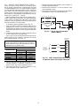
Thermostatic Expansion Valves (TXV) —
Model 30GTN,R040-110 units are available from the fac-
tory with conventional TXVs with liquid line solenoids. The
liquid line solenoid valves are not intended to be a mechani-
cal shut-off. When service is required, use the liquid line serv-
ice valve to pump down the system.
NOTE: This option is not available for modular units.
The TXV is set at the factory to maintain approximately
8 to 12° F (4.4 to 6.7° C) suction superheat leaving the cooler
by monitoring the proper amount of refrigerant into the cooler.
All TXVs are adjustable, but should not be adjusted unless
absolutely necessary. When TXV is used, thermistors T5,
T6, T7, and T8 are not required.
The TXV is designed to limit the cooler saturated suction
temperature to 55 F (12.8 C). This makes it possible for unit
to start at high cooler fluid temperatures without overload-
ing the compressor.
Compressor Protection Control System (CPCS)
or Control Relay(CR) —
Each compressor has its own
CPCS module or CR. See Fig. 13 for CPCS module. The
CPCS or CR is used to control and protect the compressors
and crankcase heaters. The CPCS and CR provide the fol-
lowing functions:
• compressor contactor control/crankcase heater
• crankcase heater control
• compressor ground current protection (CPCS only)
• status communication to processor board
• high-pressure protection
One large relay is located on the CPCS board. This relay
controls the crankcase heater and compressor contactor, and
also provides a set of signal contacts that the microprocessor
monitors to determine the operating status of the compres-
sor. If the processor board determines that the compressor is
not operating properly through the signal contacts, it will lock
the compressor off by deenergizing the proper 24-v control
relay on the relay board. The CPCS board contains logic that
can detect if the current-to-ground of any compressor wind-
ing exceeds 2.5 amps. If this condition occurs, the CPCS
shuts down the compressor.
Ahigh-pressure switch is wired in series between the MBB
and the CR or CPCS. On compressor A1 and B1 a loss-of-
charge switch is also wired in series with the high-pressure
switch. If the high-pressure switch opens during operation
of a compressor, the compressor will be stopped, the failure
will be detected through the signal contacts, and the com-
pressor will be locked off. If the lead compressor in either
circuit is shut down by the high-pressure switch, loss-of-
charge switch, ground current protector, or oil safety switch,
all compressors in that circuit are shut down.
NOTE: The CR operates the same as the CPCS, except the
ground current circuit protection is not provided.
Compressor Ground Current Protection Board
(CGF) and Control Relay (CR) —
The 30GTN,R130-
210, and associated modular units (see Table 1) contain one
compressor ground current protection board (CGF) for each
refrigeration circuit. The CGF contains logic that can detect
if the current-to-ground of any compressor winding exceeds
2.5 amps. If this occurs, the lead compressor in that circuit
is shut down along with other compressors in that circuit.
Ahigh-pressure switch is wired in series between the MBB
and the CR or CPCS. On compressor A1 and B1 a loss-of-
charge switch is also included with the high-pressure switch.
The lead compressor in each circuit also has the CGF con-
tacts described above. If any of these switches open during
operation of a compressor, the CR relay is deenergized, stop-
ping the compressor and signaling the processor at the MBB-J9
inputs to lock out the compressor. If the lead compressor in
either circuit is shut down by high-pressure switch, com-
pressor ground fault, oil pressure switch, or the loss-of-
charge switch, all compressors in that circuit are also shut
down.
Fig. 13 — Compressor Protection Control
System Module
15

Electronic Expansion Valve (EXV) (See Fig. 14)
— Standard units are equipped with a bottom seal EXV. This
device eliminates the use of the liquid line solenoid pump-
down at unit shutdown.An O-ring has been added to bottom
of orifice assembly to complete a seal in the valve on shut-
down. This is not a mechanical shut-off. When service is re-
quired, use the liquid line service valve to pump down the
system.
High pressure refrigerant enters bottom of valve where it
passes through a group of machined slots in side of orifice
assembly. As refrigerant passes through the orifice, it drops
in pressure. To control flow of refrigerant, the sleeve slides
up and down along orifice assembly, modulating the size of
orifice. The sleeve is moved by a linear stepper motor that
moves in increments controlled directly by the processor.As
stepper motor rotates, the motion is translated into linear move-
ment of lead screw. There are 1500 discrete steps with this
combination. The valve orifice begins to be exposed at
320 steps. Since there is not a tight seal with the orifice and
the sleeve, the minimum position for operation is 120 steps.
Two thermistors are used to determine suction superheat.
One thermistor is located in the cooler and the other is lo-
cated in the cylinder end of the compressor after refrigerant
has passed over the motor. The difference between the
2 thermistors is the suction superheat. These machines are
set up to provide approximately 5 to 7 F (2.8 to 3.9 C) super-
heat leaving the cooler. Motor cooling accounts for approxi-
mately 22 F (12.2 C), resulting in a superheat entering com-
pressor cylinders of approximately 30 F (16.7 C). This increases
performance of cooler by reducing the amount of superheat
needed.
Because the valves are controlled by the EXV module, it
is possible to track the position of the valve. Valve position
can be used to control head pressure and system refrigerant
charge.
During initial start-up, the EXV module will drive each
valve fully closed. After initialization period, valve position
is controlled by the EXV module and the MBB.
The EXV is used to limit the maximum cooler saturated
suction temperature to 55 F (12.8 C). This makes it possible
for the chiller to start at high cooler fluid temperatures with-
out overloading the compressor.
Energy Management Module (Fig. 15) — This
factory-installed option or field-installed accessory is used
for the following types of temperature reset, demand limit,
and/or ice features:
• 4 to 20 mA leaving fluid temperature reset (requires field-
supplied 4 to 20 mA generator)
• 4 to 20 mA cooling set point reset (requires field-supplied
4 to 20 mA generator)
• Discrete inputs for 2-step demand limit (requires field-
supplied dry contacts capable of handlinga5vdc,1to
20 mA load)
• 4 to 20 mA demand limit (requires field-supplied 4 to 20
mA generator)
• Discrete input for Ice Done switch (requires field-supplied
dry contacts capable of handling a 5 vdc, 1 to 20 mAload)
See Demand Limit and Temperature Reset sections on
pages 43 and 45 for further details.
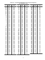
Capacity Control — The control system cycles com-
pressors, unloaders, and hot gas bypass solenoids to main-
tain the user-configured leaving chilled fluid temperature set
point. Entering fluid temperature is used by the Main Base
Board (MBB) to determine the temperature drop across the
cooler and is used in determining the optimum time to add
or subtract capacity stages. The chilled fluid temperature set
point can be automatically reset by the return temperature
reset or space and outdoor-air temperature reset features. It
can also be reset from an external 4 to 20 mA signal (re-
quires Energy Management Module FIOP/accessory).
With the automatic lead-lag feature in the unit, the control
determines randomly which circuit will start first,A or B. At
the first call for cooling, the lead compressor crankcase heater
will be deenergized, a condenser fan will start, and the com-
pressor will start unloaded.
NOTE: The automatic lead-lag feature is only operative when
an even number of unloaders is present. The 040-070 units
require an accessory unloader for the lead-lag feature to be
in effect.
If the circuit has been off for 15 minutes, and the unit is
a TXV unit, liquid line solenoid will remain closed during
start-up of each circuit for 15 seconds while the cooler and
suction lines are purged of any liquid refrigerant. For units
with EXVs, the lead compressor will be signaled to start.
The EXV will remain at minimum position for 10 seconds
before it is allowed to modulate.
After the purge period, the EXV will begin to meter the
refrigerant, or the liquid line solenoid will open allowing the
TXV to meter the refrigerant to the cooler. If the off-time is
less than 15 minutes, the EXV will be opened as soon as the
compressor starts.
The EXVs will open gradually to provide a controlled start-up
to prevent liquid flood-back to the compressor. During start-
up, the oil pressure switch is bypassed for 2 minutes to al-
low for the transient changes during start-up. As additional
stages of compression are required, the processor control will
add them. See Tables 5A and 5B.
If a circuit is to be stopped, the control will first start to
close the EXV or close the liquid line solenoid valve.
For units with TXVs, the lag compressor(s) will be shut down
and the lead compressor will continue to operate for 10 sec-
onds to purge the cooler of any refrigerant.
For units with EXVs, the lag compressor(s) will be shut down
and the lead compressor will continue to run. After the lag
compressor(s) has shut down, the EXV is signaled to close.
The lead compressor will remain on for 10 seconds after the
EXV is closed.
During both algorithms (TXV and EXV), all diagnostic
conditions will be honored. If a safety trip or alarm condi-
tion is detected before pumpdown is complete, the circuit
will be shut down.
Fig. 14 — Electronic Expansion Valve (EXV)
16

The capacity routine runs every 30 seconds. The routine
attempts to maintain the Control Point at the desired set point.
Each time it runs, the control reads the entering and leaving
fluid temperatures. The control determines the rate at which
conditions are changing and calculates 2 variables based on
these conditions. Next, a capacity ratio is calculated using
the 2 variables to determine whether or not to make any changes
to the current stages of capacity. This ratio value ranges from
−100 to + 100%. If the next stage of capacity is a compres-
sor, the control starts (stops) a compressor when the ratio
reaches + 100% (−100%). If the next stage of capacity is an
unloader, the control deenergizes(energizes) an unloader when
the ratio reaches + 60% (−60%). Unloaders are allowed to
cycle faster than compressors, to minimize the number of
starts and stops on each compressor. A delay of 90 seconds
occurs after each capacity step change.
CEBD430351-0396-01C
TEST 1
CEPL130351-01
PWR
TEST 2
J1
J2
J4 J3
J5
J6
J7
LEN
STATUS
RED LED - STATUS
GREEN LED -
LEN (LOCAL EQUIPMENT NETWORK)
Fig. 15 — Energy Management Module
17

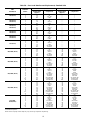
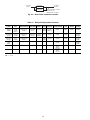
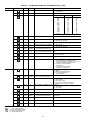
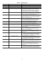
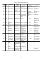
Table 5A — Part Load Data Percent Displacement, Standard Units
UNIT
30GTN,GTR
CONTROL
STEPS
LOADING SEQUENCE A LOADING SEQUENCE B
%
Displacement
(Approx)
Compressors
%
Displacement
(Approx)
Compressors
040 (60 Hz)
1 25 A1* — —
250A1 — —
3 75 A1*, B1 — —
4 100 A1,B1 — —
040 (50 Hz)
045 (60 Hz)
1 24 A1* — —
247A1 — —
3 76 A1*,B1 — —
4 100 A1,B1 — —
045 (50 Hz)
050 (60 Hz)
1 31 A1* — —
244A1 — —
3 87 A1*,B1 — —
4 100 A1,B1 — —
050 (50 Hz)
060 (60 Hz)
1 28 A1* — —
242A1 — —
3 87 A1*,B1 — —
4 100 A1,B1 — —
060 (50 Hz)
070 (60 Hz)
1 33 A1* — —
250A1 — —
3 83 A1*,B1 — —
4 100 A1,B1 — —
070 (50 Hz)
1 19 A1* — —
227A1 — —
3 65 A1*,B1 — —
4 73 A1,B1 — —
5 92 A1*,A2,B1 — —
6 100 A1,A2,B1 — —
080, 230B (60 Hz)
1 22 A1* 30 B1*
234A1 44B1
3 52 A1*,B1* 52 A1*,B1*
4 67 A1*,B1 63 A1,B1*
5 78 A1,B1 78 A1,B1
6 89 A1*,A2,B1 85 A1,A2,B1*
7 100 A1,A2,B1 100 A1,A2,B1
080, 230B (50 Hz)
1 17 A1* 25 B1*
225A1 38B1
3 42 A1*,B1* 42 A1*,B1*
4 54 A1*,B1 50 A1, B1*
5 62 A1,B1 62 A1,B1
6 79 A1*,A2,B1* 79 A1*,A2,B1*
7 92 A1*,A2,B1 88 A1,A2,B1*
8 100 A1,A2,B1 100 A1,A2,B1
090, 245B (60 Hz)
1 18 A1* 18 B1*
227A1 27B1
3 35 A1*,B1* 35 A1*,B1*
4 44 A1*,B1 44 A1,B1
5 53 A1,B1 53 A1,B1
6 56 A1*,A2,B1* 62 A1*,B1*,B2
7 65 A1*,A2,B1 71 A1,B1*,B2
8 74 A1,A2,B1 80 A1,B1,B2
9 82 A1*,A2,B1*,B2 82 A1*,A2,B1*,B2
10 91 A1*,A2,B1,B2 91 A1,A2,B1*,B2
11 100 A1,A2,B1,B2 100 A1,A2,B1,B2
090, 245B (50 Hz)
1 14 A1* 14 B1*
221A1 21B1
3 29 A1*,B1* 29 A1*,B1*
4 36 A1*,B1 36 A1,B1*
5 43 A1,B1 43 A1,B1
6 61 A1*,A2,B1* 53 A1*,B1*,B2
7 68 A1*,A2,B1 60 A1,B1*,B2
8 75 A1,A2,B1 67 A1,B1,B2
9 86 A1*,A2,B1*,B2 86 A1*,A2,B1*,B2
10 93 A1*,A2,B1,B2 93 A1,A2,B1*,B2
11 100 A1,A2,B1,B2 100 A1,A2,B1,B2
100, 255B,
270B (60 Hz)
1 16 A1* 16 A1*
223A1 23A1
3 31 A1*,B1* 31 A1*,B1*
4 39 A1*,B1 39 A1*,B1
5 46 A1,B1 46 A1,B1
6 58 A1*,A2,B1* 58 A1*,A2,B1*
7 66 A1*,A2,B1 66 A1*,A2,B1
8 73 A1,A2,B1 73 A1,A2,B1
9 85 A1*,A2,B1*,B2 85 A1*,A2,B1*,B2
10 92 A1*,A2,B1,B2 92 A1*,A2,B1,B2
11 100 A1,A2,B1,B2 100 A1,A2,B1,B2
*Unloaded compressor.
NOTE: These capacity control steps may vary due to lag compressor sequencing.
18

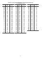
Table 5A — Part Load Data Percent Displacement, Standard Units (cont)
UNIT
30GTN,GTR
CONTROL
STEPS
LOADING SEQUENCE A LOADING SEQUENCE B
%
Displacement
(Approx)
Compressors
%
Displacement
(Approx)
Compressors
100, 255B,
270B (50 Hz)
1 13 A1* 13 B1*
220A1 20B1
3 26 A1*,B1* 26 A1*,B1*
4 33 A1,B1 33 A1,B1
5 40 A1,B1 40 A1,B1
6 57 A1*,A2,B1* 57 A1*,B1*,B2
7 63 A1*,A2,B1 63 A1,B1*,B2
8 70 A1,A2,B1 70 A1,B1,B2
9 87 A1*,A2,B1*,B2 87 A1*,A2,B1*,B2
10 93 A1*,A2,B1,B2 93 A1,A2,B1*,B2
11 100 A1,A2,B1,B2 100 A1,A2,B1,B2
110, 290B,
315B (60 Hz)
1 14 A1* 14 B1*
221A1 21B1
3 29 A1*,B1* 29 A1*,B1*
4 36 A1*,B1 36 A1,B1*
5 43 A1,B1 43 A1,B1
6 61 A1*,A2,B1* 53 A1*,B1*,B2
7 68 A1*,A2,B1 60 A1,B1*,B2
8 75 A1,A2,B1 67 A1,B1,B2
9 86 A1*,A2,B1*,B2 86 A1*,A2,B1*,B2
10 93 A1*,A2,B1,B2 93 A1,A2,B1*,B2
11 100 A1,A2,B1,B2 100 A1,A2,B1,B2
110, 290B,
315B (50 Hz)
1 17 A1* 17 B1*
225A1 25B1
3 33 A1*,B1* 33 A1*,B1*
4 42 A1*,B1 42 A1,B1*
5 50 A1,B1 50 A1,B1
6 58 A1*,A2,B1* 58 A1*,B1*,B2
7 67 A1*,A2,B1 67 A1,B1*,B2
8 75 A1,A2,B1 75 A1,B1,B2
9 83 A1*,A2,B1*,B2 83 A1*,A2,B1*,B2
10 92 A1*,A2,B1,B2 92 A1,A2,B1*,B2
11 100 A1,A2,B1,B2 100 A1,A2,B1,B2
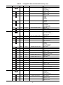
130 (60 Hz)
1
2
3
4
5
6
7
8
9
10
11
14
21
28
35
42
58
64
71
87
93
100
A1*
A1
A1*,B1*
A1*,B1
A1,B1
A1*,A2,B1*
A1*,A2,B1
A1,A2,B1
A1*,A2,B1*,B2
A1*,A2,B1,B2
A1,A2,B1,B2
14
21
28
35
42
58
64
71
87
93
100
B1*
B1
A1*,B1*
A1,B1*
A1,B1
A1*,B1*,B2
A1,B1*,B2
A1,B1,B2
A1*,A2,B1*,B2
A1,A2,B1*,B2
A1,A2,B1,B2
130 (50 Hz)
1
2
3
4
5
6
7
8
9
10
11
12
13
14
10
14
26
35
39
44
53
57
69
78
82
87
96
100
A1*
A1
A1*,B1*
A1*,B1
A1,B1
A1*,A2,B1*
A1*,A2,B1
A1,A2,B1
A1*,A2,B1*,B2
A1*,A2,B1,B2
A1,A2,B1,B2
A1*,A2,A3,B1*,B2
A1*,A2,A3,B1,B2
A1,A2,A3,B1,B2
16
25
26
31
39
51
56
64
69
74
82
87
91
100
B1*
B1
A1*,B1*
A1,B1*
A1,B1
A1*,B1*,B2
A1,B1*,B2
A1,B1,B2
A1*,A2,B1*,B2
A1,A2,B1*,B2
A1,A2,B1,B2
A1*,A2,A3,B1*,B2
A1,A2,A3,B1*,B2
A1,A2,A3,B1,B2
150, 230A, 245A,
255A (60 Hz)
1
2
3
4
5
6
7
8
9
10
11
12
13
14
11
15
29
38
42
44
53
58
71
80
85
86
95
100
A1*
A1
A1*,B1*
A1*,B1
A1,B1
A1*,A2,B1*
A1*,A2,B1
A1,A2,B1
A1*,A2,B1*,B2
A1*,A2,B1,B2
A1,A2,B1,B2
A1*,A2,A3,B1*,B2
A1*,A2,A3,B1,B2
A1,A2,A3,B1,B2
18
27
29
33
42
55
60
69
71
75
85
86
91
100
B1*
B1
A1*,B1*
A1,B1*
A1,B1
A1*,B1*,B2
A1,B1*,B2
A1,B1,B2
A1*,A2,B1*,B2
A1,A2,B1*,B2
A1,A2,B1,B2
A1*,A2,A3,B1*,B2
A1,A2,A3,B1*,B2
A1,A2,A3,B1,B2
*Unloaded compressor.
NOTE: These capacity control steps may vary due to lag compressor sequencing.
19

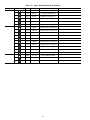
Table 5A — Part Load Data Percent Displacement, Standard Units (cont)
UNIT
30GTN,GTR
CONTROL
STEPS
LOADING SEQUENCE A LOADING SEQUENCE B
%
Displacement
(Approx)
Compressors
%
Displacement
(Approx)
Compressors
150, 230A, 245A,
255A (50 Hz)
1
2
3
4
5
6
7
8
9
10
11
12
13
14
13
20
26
33
40
46
53
60
66
73
80
86
93
100
A1*
A1
A1*,B1*
A1*,B1
A1,B1
A1*,A2,B1*
A1*,A2,B1
A1,A2,B1
A1*,A2,B1*,B2
A1*,A2,B1,B2
A1,A2,B1,B2
A1*,A2,A3,B1*,B2
A1*,A2,A3,B1,B2
A1,A2,A3,B1,B2
13
20
26
33
40
46
53
60
66
73
80
86
93
100
B1*
B1
A1*,B1*
A1,B1*
A1,B1
A1*,B1*,B2
A1,B1*,B2
A1,B1,B2
A1*,A2,B1*,B2
A1,A2,B1*,B2
A1,A2,B1,B2
A1*,A2,A3,B1*,B2
A1,A2,A3,B1*,B2
A1,A2,A3,B1,B2
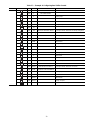
170, 270A,
330A/B (60 Hz)
1
2
3
4
5
6
7
8
9
10
11
12
13
14
15
16
17
11
17
23
28
33
39
45
50
56
61
67
73
78
83
89
95
100
A1*
A1
A1*,B1*
A1*,B1
A1,B1
A1*,A2,B1*
A1*,A2,B1
A1,A2,B1
A1*,A2,B1*,B2
A1*,A2,B1,B2
A1,A2,B1,B2
A1*,A2,A3,B1*,B2
A1*,A2,A3,B1,B2
A1,A2,A3,B1,B2
A1*,A2,A3,B1*,B2,B3
A1*,A2,A3,B1,B2,B3
A1,A2,A3,B1,B2,B3
11
17
23
28
33
39
45
50
56
61
67
73
78
83
89
95
100
B1*
B1
A1*,B1*
A1,B1*
A1,B1
A1*,B1*,B2
A1,B1*,B2
A1,B1,B2
A1*,A2,B1*,B2
A1,A2,B1*,B2
A1,A2,B1,B2
A1*,A2,B1*,B2,B3
A1,A2,B1*,B2,B3
A1,A2,B1,B2,B3
A1*,A2,A3,B1*,B2,B3
A1,A2,A3,B1*,B2,B3
A1,A2,A3,B1,B2,B3
170, 270A,
330A/B,360B (50 Hz)
1
2
3
4
5
6
7
8
9
10
11
12
13
14
15
16
17
9
14
19
23
28
33
37
42
52
57
61
72
76
81
91
96
100
A1*
A1
A1*,B1*
A1*,B1
A1,B1
A1*,A2,B1*
A1*,A2,B1
A1,A2,B1
A1*,A2,B1*,B2
A1*,A2,B1,B2
A1,A2,B1,B2
A1*,A2,A3,B1*,B2
A1*,A2,A3,B1,B2
A1,A2,A3,B1,B2
A1*,A2,A3,B1*,B2,B3
A1*,A2,A3,B1,B2,B3
A1,A2,A3,B1,B2,B3
9
14
19
23
28
38
43
47
52
57
61
72
76
81
91
96
100
B1*
B1
A1*,B1*
A1,B1*
A1,B1
A1*,B1*,B2
A1,B1*,B2
A1,B1,B2
A1*,A2,B1*,B2
A1,A2,B1*,B2
A1,A2,B1,B2
A1*,A2,B1*,B2,B3
A1,A2,B1*,B2,B3
A1,A2,B1,B2,B3
A1*,A2,A3,B1*,B2,B3
A1,A2,A3,B1*,B2,B3
A1,A2,A3,B1,B2,B3
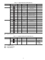
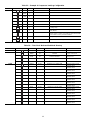
190, 290A, 360A/B,
390B (60 Hz)
1
2
3
4
5
6
13
25
41
56
78
100
A1
A1,B1
A1,A2,B1
A1,A2,B1,B2
A1,A2,A3,B1,B2
A1,A2,A3,B1,B2,B3
13
25
41
56
78
100
B1
A1,B1
A1,B1,B2
A1,A2,B1,B2
A1,A2,B1,B2,B3
A1,A2,A3,B1,B2,B3
190, 290A, 360A,
390B (50 Hz)
1
2
3
4
5
6
17
33
50
67
83
100
A1
A1,B1
A1,A2,B1
A1,A2,B1,B2
A1,A2,A3,B1,B2
A1,A2,A3,B1,B2,B3
17
33
50
67
83
100
B1
A1,B1
A1,B1,B2
A1,A2,B1,B2
A1,A2,B1,B2,B3
A1,A2,A3,B1,B2,B3
210, 315A, 390A,
420A/B (60 Hz)
1
2
3
4
5
6
7
11
25
36
56
67
86
100
A1
A1,B1
A1,A2,B1
A1,A2,B1,B2
A1,A2,A3,B1,B2
A1,A2,A3,B1,B2,B3
A1,A2,A3,A4,B1,B2,B3
14
25
44
56
75
86
100
B1
A1,B1
A1,B1,B2
A1,A2,B1,B2
A1,A2,B1,B2,B3
A1,A2,A3,B1,B2,B3
A1,A2,A3,A4,B1,B2,B3
210, 315A, 390A,
420A/B (50 Hz)
1
2
3
4
5
6
7
9
26
35
51
67
84
100
A1
A1,B1
A1,A2,B1
A1,A2,B1,B2
A1,A2,A3,B1,B2
A1,A2,A3,B1,B2,B3
A1,A2,A3,A4,B1,B2,B3
16
26
42
51
67
84
100
B1
A1,B1
A1,B1,B2
A1,A2,B1,B2
A1,A2,B1,B2,B3
A1,A2,A3,B1,B2,B3
A1,A2,A3,A4,B1,B2,B3
*Unloaded compressor.
NOTE: These capacity control steps may vary due to lag compressor sequencing.
20
Page is loading ...
Page is loading ...
Page is loading ...
Page is loading ...
Page is loading ...
Page is loading ...
Page is loading ...
Page is loading ...
Page is loading ...
Page is loading ...
Page is loading ...
Page is loading ...
Page is loading ...
Page is loading ...
Page is loading ...
Page is loading ...
Page is loading ...
Page is loading ...
Page is loading ...
Page is loading ...
Page is loading ...
Page is loading ...
Page is loading ...
Page is loading ...
Page is loading ...
Page is loading ...
Page is loading ...
Page is loading ...
Page is loading ...
Page is loading ...
Page is loading ...
Page is loading ...
Page is loading ...
Page is loading ...
Page is loading ...
Page is loading ...
Page is loading ...
Page is loading ...
Page is loading ...
Page is loading ...
Page is loading ...
Page is loading ...
Page is loading ...
Page is loading ...
Page is loading ...
Page is loading ...
Page is loading ...
Page is loading ...
Page is loading ...
Page is loading ...
Page is loading ...
Page is loading ...
Page is loading ...
Page is loading ...
Page is loading ...
Page is loading ...
Page is loading ...
Page is loading ...
Page is loading ...
Page is loading ...
Page is loading ...
Page is loading ...
Page is loading ...
Page is loading ...
-
 1
1
-
 2
2
-
 3
3
-
 4
4
-
 5
5
-
 6
6
-
 7
7
-
 8
8
-
 9
9
-
 10
10
-
 11
11
-
 12
12
-
 13
13
-
 14
14
-
 15
15
-
 16
16
-
 17
17
-
 18
18
-
 19
19
-
 20
20
-
 21
21
-
 22
22
-
 23
23
-
 24
24
-
 25
25
-
 26
26
-
 27
27
-
 28
28
-
 29
29
-
 30
30
-
 31
31
-
 32
32
-
 33
33
-
 34
34
-
 35
35
-
 36
36
-
 37
37
-
 38
38
-
 39
39
-
 40
40
-
 41
41
-
 42
42
-
 43
43
-
 44
44
-
 45
45
-
 46
46
-
 47
47
-
 48
48
-
 49
49
-
 50
50
-
 51
51
-
 52
52
-
 53
53
-
 54
54
-
 55
55
-
 56
56
-
 57
57
-
 58
58
-
 59
59
-
 60
60
-
 61
61
-
 62
62
-
 63
63
-
 64
64
-
 65
65
-
 66
66
-
 67
67
-
 68
68
-
 69
69
-
 70
70
-
 71
71
-
 72
72
-
 73
73
-
 74
74
-
 75
75
-
 76
76
-
 77
77
-
 78
78
-
 79
79
-
 80
80
-
 81
81
-
 82
82
-
 83
83
-
 84
84


Carrier 100GTN Specification
- Category
- Small kitchen appliances
- Type
- Specification
Ask a question and I''ll find the answer in the document
Finding information in a document is now easier with AI
Related papers
-
Carrier AQUASNAP 30RAP010-150 Specification
-
-
-
-
-
-
-
-
-
Other documents
-
Traceable Big-Digit 4-Alarm Digital Thermometer User manual
-
LG RCAW070PBAA Owner's manual
-
-
Sterling AquaSnap 30RA032 User manual
-
McQuay M5ACV 100 CR Specification
-
Trane ADAPTIVE CONTROL UCM-CLD Installation Operation & Maintenance
-
 Movincool CMW30 Service Manuals
-
Hydromatic Novus 4000 Standard Electrical Controls Owner's manual
-
weintek iR-Axxx Installation guide
-
 W Audio DP34258 User manual

