Page is loading ...

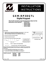
INSTALLATION
INSTRUCTIONS
FREEDOM F-64
CONTROL PANEL/COMMUNICATOR
© NAPCO 2006 WI1501A 9/06
R
For use with the Freedom F-64TP Wireless Touchpad, F-64TPG Garage Door Touchpad, the F-64TPBR
Bedroom Touchpad, F-64TP-H Hardwire Touchpad and the F-64PROG Stay/Away Programmer
Publicly traded on NASDAQ Symbol: NSSC
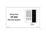
F-64PROG Programmer
SYSTEM READY
10/03/06 12:03 AM
Freedom F-64TP Touchpad

THIS MANUAL INCLUDES FEATURES WHICH ARE ONLY AVAILABLE IN THE FREEDOM F-64
CONTROL PANEL FIRMWARE VERSION 30 OR LATER.
NAPCO Security Systems, Inc.
333 Bayview Avenue, Amityville, New York 11701
For Sales and Repairs, call toll free: (800) 645-9445
For direct line to Technical Service, call toll free: (800) 645-9440
Internet: http://www.napcosecurity.com
Refer to accompanying F-64 Programming Instructions (WI1502) for programming information.
IMPORTANT NOTICE
F-64 panel version 30 requires the use of the following version programmer:
• F-64PROG Version 01
Upon entering program mode, the LCD window will flash the control panel firmware version, followed by the pro-
grammer firmware version:
• F-64PROG : [3001]
If Gemini keypads are installed in the system (in addition to the required Freedom F-64TP or F-64TP-H Touch-
pads), the following version keypads must be used:
• GEM-K1CA Version 9B
• GEM-K2AS, Version 7
• GEM-K3DGTL, Version 3
• GEM-K4/K4RF, Version 2
Differences between the GEM-P1664 and the Freedom F-64 Control Panels:
The GEM-P1664 control panel and the Freedom F-64 V30 control panel are identical, except for the following:
• The "Classic" Gemini RP-Series keypads cannot be used with the Freedom F-64 V30 control panel.
• The Perimeter Group Bypass zone feature is exclusive to the Freedom F-64 V30 control panel.

L NAPCO Security Systems
Freedom F-64 Installation Instructions
WI1501A 9/06
Page 3
TABLE OF CONTENTS
INTRODUCTION ....................................................................................................................................................................... 4
General Description ................................................................................................................................................................... 4
Features .................................................................................................................................................................................... 4
Specifications ............................................................................................................................................................................ 5
Ordering Information .................................................................................................................................................................. 6
Summary of UL Requirements .................................................................................................................................................. 7
INSTALLATION ........................................................................................................................................................................ 8
Mounting ................................................................................................................................................................................... 8
Wiring ........................................................................................................................................................................................ 9
Wireless Systems ...................................................................................................................................................................... 9
Typical Residential Fire Installation ........................................................................................................................................... 9
Typical Partitioned Installation ................................................................................................................................................... 9
TESTING THE SYSTEM ......................................................................................................................................................... 10
WIRING CONNECTIONS ........................................................................................................................................................ 11
Battery ..................................................................................................................................................................................... 11
Transformer ............................................................................................................................................................................. 11
Siren/Bell Output ..................................................................................................................................................................... 11
Auxiliary Power ........................................................................................................................................................................ 11
PGM Outputs .......................................................................................................................................................................... 11
Remote Bus ............................................................................................................................................................................ 12
Earth Ground ........................................................................................................................................................................... 12
Zone Configuration Styles ....................................................................................................................................................... 13
Basic Zone Configuration ................................................................................................................................................... 13
EZ Zone Doubling Configuration ........................................................................................................................................ 13
4-Wire Smoke Detectors ......................................................................................................................................................... 14
2-Wire Smoke Detectors ......................................................................................................................................................... 14
Telephone Lines ...................................................................................................................................................................... 15
KEYPAD / TOUCHPAD MESSAGES ..................................................................................................................................... 16
GLOSSARY ....................................................................................................................................................................... 17-35
STANDBY-BATTERY CALCULATION WORKSHEET ........................................................................................................... 36
WIRING LEGEND ................................................................................................................................................................... 37
CP-01 QUICK REFERENCE CHART ...................................................................................................................................... 38
FACTORY DEFAULT DESCRIPTION .................................................................................................................................... 40
FCC STATEMENT .................................................................................................................................................................. 42
F-64 WIRING DIAGRAM ......................................................................................................................................................... 43
LIMITED WARRANTY ............................................................................................................................................................ 44

Freedom F-64 Installation Instructions
L NAPCO Security Systems
WI1501A 9/06
Page 4
INTRODUCTION
GENERAL DESCRIPTION
Napco's Freedom F-64 is a state-of-the-art microcomputer-based burglary and residential fire alarm control panel of modular
design. Integrally an 8-zone panel, it will support up to 64 zones with the use of zone doubling, optional zone expansion
modules, wireless receiver modules and/or Freedom 64 Touchpads. Each panel includes an integral digital communicator.
The F-64 panel operates with the NAPCO Freedom 64 Touchpads, providing a complete Deadbolt-Activated Home Protection
System that combines intuitive interactive arming with passive disarming. The Touchpads provide a system which is not only
effortless to use, but also 100% false alarm resistant during the critical arming and disarming sequences. See WI1499 for
more information about the Freedom Touchpads.
The control panel features programmable area partitioning. That is, the system may be divided into up to 4 discrete multiple-
zone areas, each allowing access by only those users programmed for their respective area.
Opening Suppression and Closing Suppression, available through Napco Quickloader software, suppress reporting within
programmed “windows”. Conversely, Exception Reporting can transmit a “fail to close” if the panel is not armed within
programmed intervals and, similarly, a “fail to open” if the panel is not disarmed within programmed intervals. Furthermore, the
panel can be programmed to automatically arm either area at any time. A log containing up to 400 events (accessible through
Quickloader
TM
software) monitors control-panel activity referenced to a precision real-time clock. A detailed event history may
be displayed at the computer, using Napco’s PCD-Windows Quickloader Software.
Touchpads feature a liquid-crystal display for messages. In normal use, the LCD shows zone identification and status
messages, and the log can also be viewed. Conventional LEDs and a sounder are also provided for annunciation.
Data may be quickly and easily downloaded to the control panel using a PC-compatible computer with Napco's PCD-Windows
Quickloader software and PCI2000 computer interface. Or, the panel may be programmed using the F-64PROG program-
mer. In the programming modes (there are two: Dealer and User), the LCD shows memory address, data values,
programming prompts, and the alphanumeric characters required for entering up to 64 user codes and custom zone
descriptions. NOTE: Failure to install and program as described in this manual for UL Listed systems voids the
Listing Mark of Underwriters Laboratories, Inc.
FEATURES
Control Panel Features
Eight end-of-line-resistor burglary zones programmable
for Area (expandable to sixteen end-of-line resistors with
zone doubling or series zone doubling with loop supervi-
sion), Exit/Entry Delay, Interior (Stay) Bypass, Exit/Entry
Follower, Day Zone, Chime, Fire options, Swinger
Shutdown, Zone Anding and a variety of other features.
Supports up to 64 zones with optional zone-expansion
modules, wireless receiver modules and 4-zone Touch-
pads.
Supports up to 64 individually coded users.
Supports three outputs (Bell, PGM1 and PGM2) and up to
16 external outputs (using Relay Module RB3008,
RM3008 or the GEM-OUT8. See Relay Control in glos-
sary for more information).
Supports three Touchpad panics: Fire, Police & Auxiliary.
Supports four independent area partitions.
Supports up to seven separate access stations
(Touchpads) by up to 64 users.
Supports up to 16 separately-addressable X-10 devices
with the GEM-X10 KIT and PC04 interfaces.
English-language prompts & system status messages.
User Codes and Zone Descriptions outside assigned ar-
eas are able to be blocked from Touchpad display.
User-customized zone descriptions, re-programmable as
required.
Supports 2-wire and 4-wire smoke detectors.
Reports alarms, restores and troubles by zone.
400 Event Log.
Two programmable entry delay times.
One Interior Zone Group.
Dynamic battery test interrupts charging and places
battery under load every four hours.
Two Chimes by zone; programmable duration.
Quickloader programmable.
2 PGM outputs.
Supports Gemini Wireless Devices.
Communicator Features
Compatible with all major receiver formats, including 4/2,
SIA and Point ID (except Radionics Modem II).
Rotary dial and TouchTone
TM
with Rotary backup.
Three 20-digit telephone numbers.
Backup Reporting; Double Reporting; Split Reporting.
64 User Codes with Opening/Closing -Reporting by user.
AC Failure Reporting with programmable report delay.
Supervised telephone line with a fixed 60 second delay.
Pager capability.
F-64PROG Programmer Features
English-language LCD display; LED and sounder
annunciators.
Fault-Find diagnostics simplify troubleshooting.
SIA CP-01 Features.
See page 38 for complete information regarding how the
Factory Program complies with the Security Industry As-
sociation False Alarm Reduction Control Panel-01 Stan-
dard (SIA FAR CP-01).
Features

L NAPCO Security Systems
Freedom F-64 Installation Instructions
WI1501A 9/06
Page 5
SPECIFICATIONS
Freedom F-64 Control Panel
O
perating Temperature: 0-49°C (32-120°F)
Input Power: 16.5-18.0 VAC via CLASS 2 Plug-In 20VA, 40VA or 50VA Transformer
Loop Voltage: 10-13Vdc
Loop Current: 3mA without Zone Doubling, 2.4mA with Zone Doubling using a 2.2K Ohm end-of-line resistor (Model EOL2.2K);
5mA for 2-wire smoke-detector zones; 1.4 mA using a 3.9K Ohm resistor (Model EOL3.9K) with Zone Doubling; 3mA with Se-
ries Zone with Loop Supervision and 3mA with Series Zone Doubling with Loop Supervision
Loop Resistance: 300 Ohm max.; 50 Ohm for 2-wire smoke-detector zones
Alarm Voltage Output: 1
Programmable Negative Outputs: 2
Auxiliary Power Output: 11.7-12.5 VDC
Remote Power Output: 12 VDC regulated (for the F-64PROG programmer)
Combined Standby Current (Remote Power + Aux. Power + Fire Power): See following charts.
NOTE:
(1)
Alarm current can be increased by reducing standby current by the same amount.
* Not evaluated by UL.
** Commercial Burglary specifications not evaluated by UL.
16.5VAC
TRANSFORMER
BATTERY
(12 VDC)
STANDBY
CURRENT
ALARM
CURRENT
STANDBY
TIME
40VA/50VA 7 AH 550 mA 450 mA
(1)
4 Hours
20VA* 7 AH 500 mA 2.0 A 4 Hours
20VA* 7 AH 500 mA 2.0 A 6 Hours
RESIDENTIAL BURGLARY & COMMERCIAL BURGLARY**
16.5VAC
TRANSFORMER
BATTERY
(12 VDC)
STANDBY
CURRENT
ALARM
CURRENT
STANDBY
TIME
40VA/50VA 7 AH 120 mA
520 mA
(1)
24 Hours
40VA/50VA * Two 7 AH 360 mA
280 mA
(1)
24 Hours
20VA * 7 AH 120 mA
360 mA
(1)
24 Hours
20VA * Two 7 AH 360 mA
120 mA
(1)
24 Hours
COMBINATION RESIDENTIAL FIRE & RESIDENTIAL BURGLARY
FOR ALL UL INSTALLATIONS
"ENABLE RESIDENTIAL FIRE" (ADDRESS 1422) MUST BE PROGRAMMED
The feature "Enable Residential Fire" (address 1422, option 4) must be programmed for ALL UL installations.
"DISABLE SYSTEM TROUBLE AUDIBLE TIMEOUT" (ADDRESS 2051) MUST BE PROGRAMMED
The feature "Disable System Trouble Audible Timeout" (address 2051, option 7) must be programmed for ALL UL
installations.
To program, please refer to the F-64 Programming Instructions (WI1502) for further information.
EZM Module: GEM-EZM4/8: Input, 50mA
Keypad Current: See keypad Installation Instructions.
Maximum Number of Keypads / Touchpads: 7
Maximum Wiring Length for each run (#22AWG): 1000' divided by total number of keypads /
Touchpads and EZMs on run
Keypad Dimensions: 4” x 5” x 1” (HWD); 11.1cm x 14.9cm x 2.7cm (HWD)
Specifications

Freedom F-64 Installation Instructions
L NAPCO Security Systems
WI1501A 9/06
Page 6
ORDERING INFORMATION
System Components
F-64: Residential UL-Listed Burg and Fire Control Panel
F-64PROG: 32-Character LCD Burg & Fire Programmer
F-64TP: Wireless Touchpad
F-64TPG Garage Door Touchpad*
F-64TPBR Bedroom Touchpad
F-64TP-H Hardwired Touchpad*
Optional Accessories and Peripherals
GEM-EZM8: 8 Zone Expansion Zone Module
GEM-EZM4/8: 4-16 Zone Expansion Zone Module*
GEM-RECV8: Wireless Receiver, 8 Zones
GEM-RECV16: Wireless Receiver, 32 Zones
GEM-RECV96: Wireless Receiver, 64 Zones
GEM-TRANS2: Window/Door Transmitter, 2-Point
GEM-RTRANS: Recessed Window/Door Transmitter
GEM-KEYF: Keyfob Transmitter
GEM-SMK: Wireless Smoke Detector
GEM-PIR: Wireless PIR
GEM-PIRPET: Wireless Pet Immune Transmitter*
GEM-RS232: Isolated Computer Interface
GEM-DT: Wireless Dual-Technology Sensor
GEM-GB: Wireless Glass-Break Detector*
GEM-X10KIT: X-10 Interface*
GEM-OUT8: 8 output active low output module
F-GDMS: Freedom Garage Door Motor Sensor
F-LTRANS: Freedom Wireless Transmitter
F-IFOB: Alarm-Silencing Credential I-FOB
RM3008: Relay Module (in enclosure)
M278: Line-Reversal Module
PS3002: Power-Supply Module, 13.2Vdc, 1.9A*
EOL2.2K: End-of-Line Resistor Assy., 2.2k Ohm
EOL3.9K: End-of-Line Resistor Assy., 3.9k Ohm for
Zone Doubling*
EOL4.7K: End-of-Line Resistor Assy., 4.7k Ohm*
FT2200: End-of-Line Relay/Resistor Supervisory Module
RB1000: Relay Board, single output*
RBATH1: Dual Battery Harness*
RPB-3: Universal Keypad Mounting Box*
TRF11: Transformer, 16.5Vac/40VA, Class 2*
TRF14: Transformer, 16.5Vac/50VA, Class 2
WL1: Wire Assembly with Lug Connector, 20” *
VERI-PHONE: Two-Way Voice/Listen-In Module*
PCD-Windows: Downloading Software (for Windows)
for IBM PC-Compatible, V5.0 or greater
PCI2000/3000: Software Interface for IBM PC-
Compatible Computer*
PCI-MINI: Notebook Computer Interface*
W834-1: Keypad Cable, plug-in (20”)*
OI318: User Guide, Freedom F-64TP Touchpad
OI319: User Guide, F-64TPBR Bedroom Touchpad
OI320: User Guide F-64TPG Garage Touchpad
WI1501: F-64 Installation Instructions
WI1502: F-64 Programming Instructions (using the F-
64PROG programmer).
WI1499: Wireless F-64TP Mounting Instructions
WI1508: F-64TPG Garage Touchpad Installation In-
structions
WI1505: F-64TPBR Installation Instructions
WI1452: Freedom Garage Door Motor Sensor Installa-
tion Instructions
WI1438: Freedom F-LTRANS Wireless Transmitter In-
stallation Instructions
WIZARD IIe: Telephone Interface Module*
UL Listings
Household Burglar Alarm System Units: UL1023
Household Fire Warning System Units: UL985
Security Industry Association (SIA) False Alarm Reduc-
tion Standard CP-01
Napco Group Europe Ltd.
Libra Wireless Transmitters and Receivers for connec-
tion to Napco Intruder Control Panels (Operates on
433MHz, European Approved Frequency)
WI925: LIBRA-RECVXP-433 Wireless 8 Zone Receiver
WI924: LIBRA-RECV8-433, LIBRA-REC16433, LIBRA-
REC96433, Wireless 8/16/96 Zone Receiver
WI923: LIBRA-TRANS433, Wireless Door Contact
WI929: LIBRA-PIR433, Wireless PIR
WI931: LIBRA-KEYF433, Wireless Keyfob
WI930: LIBRA-SMK433, Wireless Smoke Detector
WI928: LIBRA-GB433, Wireless Glass Break Sensor
*Not Investigated by UL
** Pending
Ordering Information

L NAPCO Security Systems
Freedom F-64 Installation Instructions
WI1501A 9/06
Page 7
Smoke Detectors, 4-Wire:
1. ESL 445AT, 445C, 445CT, 445CR, 445CRT
2. Hochiki America SLG-12 with YBC-RL4-RA Base
3. System Sensor 2312/24T; 1412; 1412TH; 2412TH
Subtract total smoke-detector alarm current from available standby current.
Note: Any normally-open devices that do not require power from the control panel, such as pull stations and
thermostats may be used if acceptable to the Authority having Jurisdiction.
UL Compatible Smoke Detectors (Providing UL Recognition or Listing)
Manufacturer 4-Wire
Smoke Detector
2-Wire
Smoke Detector *
Smoke Detector
Base
Napco FW-4 FW-2
Sentrol
System
Sensor
449AT
449C
449CRT
449CST
449CSRT
449CSRH
449CSST
449CLT
449CSLT
449CTE
741U
742U
712U
722U
732U
711U
721U
721UT
731U
1112
2112
2112T
2112TSRB
2100
2100T
1100
701U
702U
702RE
702RU
Note: * Voltage Rating: 8.5-13.3 VDC, Maximum Number of Detectors: 10
SUMMARY OF UL REQUIREMENTS
Residential
Recognized Limited-Energy Cable for initiating, indicating and supplementary circuits.
FT2200 End-of-Line Relay for Fire (if using 4-wire smoke detectors)
Minimum alarm timeout of 5 minutes
Maximum exit time: 60 seconds
Maximum entry time: 45 seconds
Do not program “Swinger Shutdown”, “Auto-Bypass” or “50 ms Loop Response”
“Abort Delay” may not exceed 45 seconds
Program “Disable Callback Download”
Automatic dialer may not dial a police station number that has not been dedicated for such service
System must be tested at least weekly under AC/battery and Battery-Only conditions
Replace the rechargeable battery at least every 5 years
If the battery is heavily discharged, replace it or have it tested by a qualified technician
For silent panic, connect only to UL-listed holdup devices
All zones must be programmed for “Priority”
Do not program any zones for “Keyswitch Arming”
System must be serviced at least once every year
Residential Fire and Combination Residential Fire & Burglary must program “Residential Fire”
Touchpad / Keypad Expansion (EZM) Zones are not to be used as fire zones
Touchpad / Keypad Auxiliary is not to be selected
The Freedom F-64 series Touchpads must have labels placed on only the appropriate Touchpad keys (Fire, Police and
Auxiliary) that are operational
Install in accordance with the NEC/CEC requirements
"Force Arm" and "Selective Bypass" must not be programmed for UL installations
UL Compatible Sounding Appliance:
Wheelock AH-12WP
Smoke Detectors & Summary of UL Requirements

Freedom F-64 Installation Instructions
L NAPCO Security Systems
WI1501A 9/06
Page 8
INSTALLATION
MOUNTING
Control Panel
Choose a mounting location accessible to (a) a continuously-powered AC source, (b) system ground, a steel or copper
ground rod, ideally no further away than 10 feet, and (c) telephone lines (keep telephone wiring away from keypad /
Touchpad wires). Remove appropriate knockouts for cables. Place the control panel at a convenient viewing height
and mark the mounting holes. Attach the enclosure using screws suitable for the mounting surface.
Grounding
Connect the control-panel grounding screw to a metal cold-water pipe or a long steel (or copper) ground rod driven
deeply into the earth. Do not use a gas pipe, plastic pipe or AC ground connections. Use at least 16-gauge wire.
Make the run as short and direct as possible, without any sharp bends in the wire.
F-64PROG Programmer
For complete programming, the F-64PROG can be used. To simplify programming, the connector used to wire the F-
64TPTouchpad to the system buss can also be used with the F-64PROG. To program, first swap the Touchpad for a
F-64PROG programmer, then set the panel jumper from "Normal" to "Configuration". See WI1502 for complete panel
programming information.
For normal use, a maximum of 4 Touchpads (of any type) and up to 3 additional Gemini "K Series" keypads may be
permanently added to the system. Touchpads should be located near each exit/entry door. Before mounting the
Touchpad onto the wall, push the Sliding Label Plate (with label and felt backing affixed and handle facing forward)
down the guides at the rear of the Touchpad until it snaps into place. Once installed, the Sliding Label Plate cannot be
removed without first removing the Touchpad from the wall. Note: (1) The Touchpad fire and panic keys should not be
considered a substitute for a listed manual initiating device, such as a pull box. (2) Each Touchpad includes provisions
for four additional zones. See ADDING EXPANSION ZONES.
If installing the onto a double-gang box, insert mounting screws through the two vertical elongated holes on the left side
of the case and into the box. If the box is visible when viewed from the front, adjust the Touchpad vertically and tighten
the screws. Then, using hardware suitable for the mounting surface, add one or two screws at the right side of the
Touchpad case directly into the wall to ensure a secure installation. Note: Do not overtighten the screws! Uneven
walls may cause the Touchpad case to distort. See WI1499 for more information about installing an F-64TP Touch-
pad.
CAUTION: This equipment generates and uses radio-frequency energy. If not installed using conventional installation
practices for RF devices, it may cause interference to radio and television reception. It has been tested and found to
comply with the limits for a Class A computing device pursuant to Subpart B of Part 15 of FCC Rules, which are
designed to provide reasonable protection against such interference. However, there is no guarantee that
interference will not occur in a particular installation. If it has been found to cause interference to radio or television
reception, which can be determined by removing and reapplying AC and battery power to the equipment, the installer
should try to correct the interference by one or more of the following measures: reorient the receiving antenna;
connect the power transformer to a different outlet so that the control panel and receiver are on different branch
circuits; relocate the control panel with respect to the receiver.
Mounting

L NAPCO Security Systems
Freedom F-64 Installation Instructions
WI1501A 9/06
Page 9
Wiring
Wire Touchpad(s), zones, expansion zone modules and output devices as shown on the Wiring Diagram. Note that
the Wiring Diagram contains important information not available elsewhere in this manual.
Adding Expansion Zones
The F-64 control panel can support up to 16 zones as is, however this number may be increased to as many as 64
programmable zones using optional expansion zone modules (EZMs).
Wireless Systems
With the addition of at least one GEM-RECV series receiver, the F-64 will support up to 64 wireless transmitters. The
panel can accommodate one or two receivers within the premises, responding to the one with the stronger transmitter
signal. If any transmitters are selected for the default program, a GEM-RECV receiver will automatically be
programmed.
The Touchpad can display the status of any transmitter, indicating the condition of the zone (normal or open) and
transmitter troubles (low battery, tamper or supervisory failure), and signal strength of the last transmission. A receiver
failure will be indicated by “E06-NN” (“no response”, with NN representing the receiver number).
TYPICAL RESIDENTIAL FIRE INSTALLATION
(Where permitted by local codes)
At least one smoke detector should be installed directly outside
each sleeping area. If there is more than one floor, additional
smoke detectors should be installed on each level, including the
basement. The living-area and basement smoke detectors
should be installed near the stairway of the next upper level.
For increased protection, additional detectors should be installed
in areas other than those required, such as the dining room,
bedrooms, utility room, furnace room, and hallways. Heat
detectors, rather than smoke detectors, are recommended in
kitchens, attics, and garages due to conditions that may result in
false alarms and improper operation. Large areas and areas with
partitions, ceiling beams, doorways, and open joists will require additional detectors.
Refer to NFPA Standard No. 74 (National Fire Protection Association, Batterymarch Park, Quincy, MA 02269) for
additional information, including proper mounting of detectors.
TYPICAL PARTITIONED INSTALLATION
(4 Partitions Available) The system supports (4) areas but only areas 1 and 2
support Touchpads. In addition, Touchpads can only control the area to which
they are assigned.
Described and illustrated here are an example of a partitioned
system with common-area protection of the control-panel room. This
system meets UL requirements for a partitioned system.
All areas must be owned and managed by the same person(s).
All areas must be part of one building at one street address.
The control panel and all wiring protecting each partitioned area
must be confined to the respective area and may not impinge upon the
other areas. This requires that the control panel room have redundant
protection; that is (a) multiple sets of door contacts, each wired to a
separate zone and (b) one of those zones programmed for each area. In order to gain access to this protected
area without causing an alarm, both partitions must be disarmed. In lieu of redundant protection, 24-Hour Zones
may be used. Any zone protecting the control panel and transformer may not be programmed for bypass.
The sounding device must be placed such that the bell test can be heard by all partitions. Note: NFPA 74
(Household Fire Warning Equipment) requires that a fire alarm audible device be installed indoors.
The User
Program Code is not to be given to anyone except the authority responsible for all partitions.
CAUTION: Do not run telephone wiring near speaker wires; do not run keypad / Touchpad wiring with loop wiring.
Wiring

Freedom F-64 Installation Instructions
L NAPCO Security Systems
WI1501A 9/06
Page 10
TESTING THE SYSTEM
After installation is completed, test the system as follows.
1. Call the central station to inform them of the test.
2. Initiate an alarm, preferably on a zone that activates a steady siren, and verify proper signalling.
3. Call the central station to confirm their receipt of a good transmission.
Note: Be sure to test all enabled Touchpad panics.
Signal Strength Testing/Wireless Systems
To test the operation of wireless transmitters, proceed as follows.
1. Enter the Fault-Find mode. (See Touchpad Menu Mode in WI1502. Panel must be disarmed).
2. Fault a point of the transmitter to be tested by opening the loop. If the signal strength of the
transmitter is 3 or greater, the Touchpad will beep, as follows:
3. Restore the wireless point (close the loop).
The transmitter signal strength will be displayed on a scale of 3-10 with 3 considered marginal and 10
considered excellent. Note that if the signal strength is less than 3, the Touchpad will not beep and the
strength will not be displayed. Except in the Fault-Find mode, signal strengths less than 3 will be entered
into the system log. Upon zone restore, the Touchpad will beep once.
Signal Power Beeps
0-2 0
3 1
4-5 2
6-7 3
8-10 4
Testing the System

L NAPCO Security Systems
Freedom F-64 Installation Instructions
WI1501A 9/06
Page 11
WIRING CONNECTIONS
BATTERY
The RED (+) and BLACK (-) flying leads must be connected
to a 12VDC 4-7 AH Rechargeable Battery, to serve as
backup power in the event of AC Power Failure. NOTE: To
calculate the available standby time refer to the Standby-
Battery Calculation Worksheet at the back of this manual.
TRANSFORMER
(The following applies to installations in the United States of America): Connect
a 16.5 VAC Transformer to Terminals 1 and 2, using a wire of #18 AWG. or
larger at a distance of 15 ft. or less from the control panel. NOTE: Do not
connect to a switched outlet.
Connect the alarm sounding devices (self-contained sirens,
speakers or a mechanical bell) to Terminals 3 and 4. Any self-
contained siren requiring a 12 VDC input can be connected.
When connecting a mechanical bell, it must be supervised
using a 2.2k Ohm resistor. To connect 8 Ohm Speakers use a
Siren Driver with the proper polarity observed. NOTE: Refer to
the F-64 Panel Wiring Diagram for alarm current specification.
Note: In NFPA Household Fire Installations, only a single si-
ren or bell can be used on this bell circuit.
SIREN/BELL POWER
AUXILIARY POWER
Connect the auxiliary devices (motion detectors, glass breaks, etc.) to Terminals 5
and 6. Auxiliary Power provides 11.7-12.5 VDC nominal output which is used for
powering auxiliary devices. NOTE: To calculate the available standby time refer to
the Standby-Battery Calculation Worksheet at the back of this manual.
PGM OUTPUTS (PGM1 & PGM2)
PGM1 and PGM2 are negative switched
programmable outputs that can be activated
depending on the programming options
selected (see F-64 Panel Programming
Instructions). Connect the device controlled by
the programmable output between terminal 5
(+) and the PGM output (-), either terminal 7 or
8. As an example, the connection to the
RB1000 Relay Module is shown.
7
Wiring Connections: Battery, Transformer, Siren Power, Aux. Power & PGM Outputs

Freedom F-64 Installation Instructions
L NAPCO Security Systems
WI1501A 9/06
Page 12
ADDITIONAL
EZMs
AVAILABLE DEVICES
1. KEYPADS: GEM-RP2AS & GEM-RP1CAe2
2. X-10 INTERFACE: GEM-X10
3. WIRED ZONE EXPANDER: GEM-EZM816
4. WIRELESS RECEIVERS: GEM-RECV8, GEM-RECV16 & GEM-RECV96
5. RELAY MODULE: RM3008
6. VOICE INTERFACE: GEM-EVA
7. TELEPHONE INTERFACE: WIZARD2
(GEM-RP1CAe2)
2 LINE KEYPAD
REMOTE BUS
REMOTE BUS
NOTE: Refer to the EZM Installation Instructions for
specific wiring information.
Connect the available devices as shown above to the remote bus terminals (9, 10, 11 & 12). Observe the correct
color wire connections. When connecting the Touchpads, first configure them accordingly (refer to the Touchpad
Configuration Mode in WI1502). Up to four Touchpads may be connected if the longest cable run from the panel, to
the farthest Touchpad (daisy chained or home-run) is less than 1000 feet. The maximum distance for seven key-
pads/Touchpads is 300 feet using 22 AWG. wire. NOTE: When running keypad/Touchpad wire, avoid wiring parallel
to other types of wiring.
EARTH GROUND
NOTE: Do not use a gas pipe, plastic
pipe or AC ground connections.
Connect the control panel EARTH GROUND screw to a metal cold-water
pipe using at least a #16 AWG. wire. Do not use a gas pipe, plastic pipe
or AC ground connections. Also, connect the circuit board to the metal
enclosure. Connect a wire with a ground lug crimped or soldered onto
one end of the EARTH GROUND screw to the cabinet.
NOTE: Grounding connections should avoid bends in the grounding wire
whenever possible.
AVAILABLE DEVICES
1. TOUCHPADS / KEYPADS: (3 maximum) F-64PROG: 32-Character
LCD Burg & Fire Programmer*, F-64TP: Wireless Touchpad, F-
64TPG Garage Door Touchpad*, F-64TPBR Bedroom Touchpad, F-
64TP-H Hardwired Touchpad*
2. X-10 INTERFACE: GEM-X10 (16 devices maximum)*
3. WIRED ZONE EXPANDER: GEM-EZM4/8EX*, GEM-EZM4/8* (64
zones maximum)
4. WIRELESS RECEIVERS: GEM-RECV8, GEM-RECV16, GEM-
RECV96 (64 zones maximum)
5. RELAY MODULE: RM3008 (16 relays maximum)
6. VOICE INTERFACE: GEM-EVA 1*
7. TELEPHONE INTERFACE: WIZARD IIe*
Example:
F-64TP Touchpad
* Not evaluated by UL
Wiring Connections: Remote Bus & Earth Ground

L NAPCO Security Systems
Freedom F-64 Installation Instructions
WI1501A 9/06
Page 13
The basic zone configuration for the F-64 Panel is 8
zones. Connect as shown above to terminals 13-24.
Normally Closed (N.C.) devices may be wired in series
or Normally Open (N.O.) devices may be wired in
parallel. Use the 2.2K Ohm end-of-line (E.O.L.) resistor
in each zone, if selected in programming (refer to the F-
64 Programming Instructions WI1502). Zones 1-8 can
be selected for a “Fast Loop Response (50 ms)” or a
“Normal Loop Response (750 ms)”. Other zone options
include Zone Type (Entry/Exit, Interior, 24 Hour Protection, Trouble and Fire), Instant, Chime, Area Selection and
PGM Output selection. Additional expansion zone modules or wireless sensor transmitters/receivers can be used
to obtain zones numbered 9 through 32.
EZ ZONE DOUBLING
TM
CONFIGURATION
The control panel zone configuration may be expanded
from 8 to 16 zones without the use of EZM Modules. To
do so simply select “EZ Zone Doubling” in programming
(refer to the F-64 Panel Programming Instructions WI1502)
and connect zones as shown above. NOTE: If both zones
in a zone-pair configuration (ex: zones 1 & 9 in the above
diagrams) are to be used, then normally closed devices
must be wired to both zones. The 3.9K EOL resistor must
be placed at the end of the loop of the higher zone and the
2.2K EOL resistor must be placed at the end of the loop of
the lower zone.
If Normally open zones for fire or panic devices are required, then the lower zone (2.2K EOL resistor) must be used
and the higher zone (3.9K EOL resistor) must not be programmed for any area. Additional expansion zone
modules or wireless sensor transmitters/receivers can be used to obtain zones numbered 9 through 32
WARNING: Assigning a fire zone or keyswitch zones to a zone doubled will disable the respective complimentary
zone. For example, if zone 8 is assigned as a fire zone, it will disable zone 16. If zone 3 is assigned as a fire zone, it
will disable zone 11.
(–)
BASIC ZONE CONFIGURATION
Wiring Connections: Basic Zone Configuration & EZ Zone Doubling Configuration

Freedom F-64 Installation Instructions
L NAPCO Security Systems
WI1501A 9/06
Page 14
Two-wire smoke detectors can only be connected to zones 7 and 8. To use
them, select fire zone programming option and select 2-wire smoke detector
programming option for the desired fire zone 7 or 8 (refer to the F-64 Panel
Programming Instructions) and set JP3 to the “2-WF” position as shown.
Connect the 2-wire smoke detectors as shown.
If the Zone Doubling is used (see EZ Zone Doubling Configuration), the
respective complementary zones (15 & 16) are disabled when 2-wire smoke
detectors are connected to zones 7 & 8.
If Fire Alarm Verification is desired to reset the smoke detectors, select this
option for the desired fire zone (zone 7 or 8).
4-WIRE SMOKE DETECTORS
2-WIRE SMOKE DETECTORS
4-WIRE SMOKE DETECTOR WIRING
The F-64 Panel can use conventional 12 VDC 4-wire smoke detectors. To use
them, select fire zone programming option and do not select 2-wire smoke
detector programming option for the desired fire zone (refer to the F-64 Panel
Programming Instructions). Set JP3 to the position as shown, if zones 7 or 8 are
to be used.
Four wire smoke detectors may be connected to any programmed fire zone (1-8)
as shown, within the panel. If the Zone Doubling is used (see EZ Zone Doubling
Configuration), the respective complementary zones (9-16) are disabled when 4-
wire smoke detectors are connected to zones 1-8. If external EZMs are used for
zones 9-64, then 4-wire smoke detectors may be connected to any programmed
fire zones (9-64).
Power must be obtained from terminal 25 and 6. If Fire Alarm Verification is
desired to reset the smoke detectors, select this option for the desired fire zone.
2-WIRE SMOKE
DETECTOR WIRING
Wiring Connections: 4-Wire Smoke Detectors & 2-Wire Smoke Detectors

L NAPCO Security Systems
Freedom F-64 Installation Instructions
WI1501A 9/06
Page 15
Model 368 Cord
TELEPHONE LINES
Connect the Model 368 Cord as follows: 26 (RED = Telco Ring), 27 (GREEN = Telco Tip), 28 (GRAY = Home Ring)
and 29 (BROWN = Home Tip). Insert the modular plug into an approved USOCRJ31X jack (or a CA31A jack for
Canadian installations). The Telco Line is used by the control panel to dial the central station and for downloading.
This line should not be connected to party lines or coin operated telephones. If connected to a line with call waiting,
then call waiting interrupt numbers must be programmed into the CS Telephone Numbers (refer to the F-64
Programming Instructions).
When communicating to central station and during downloading, the control panel seizes the telephone lines from the
house phones, rendering them inoperative during communication. Upon completion of central station
communication, the telephone line is restored to the house phones.
RING TIP TIP RING
TIP
RING
Wiring Connections: Telephone Lines

Freedom F-64 Installation Instructions
L NAPCO Security Systems
WI1501A 9/06
Page 16
KEYPAD / TOUCHPAD MESSAGES
The F-64PROG Programmer and Touchpads can display the below messages. Note: See page 6 for a listing of the keypad /
Touchpad specific User Guides available. These User Guides contain more details regarding the various messages.
SYSTEM READY - All zones operating; system can be armed. 1
through 4 = Area.
ARMING YYY/XXX SECONDS - Exit delay in progress. XXX = exit
time remaining in 10-second decrements; YYY = AWAY or
STAY. Arming then becomes ARMED.
DISARM NOW/XXX SECONDS - Entry delay in progress. XXX =
entry time remaining in 10-second decrements.
SYSTEM ARMED - Panel armed.
ZONE FAULTED - One or more zones not secured. Display status
for zone description(s).
CAN'T ARM SYSTEM/ZONE FAULTED - Arming attempted with
Priority Zone in trouble. Secure zone to arm.
DAY ZONE TROUBLE - Trouble condition on Day Zone, followed
by one or more zone descriptions.
INVALID ENTRY/TRY AGAIN - Wrong code/time/area number
entered.
CAN'T ARM SYSTEM/PRESS RESET KEY - Arming attempted
with System Trouble present. Press RESET and then arm the
system.
ALARM - Alarm condition, followed by one or more zone
descriptions.
FIRE ALARM - Alarm condition on a Fire Zone. Enter your code
then press the
U button to silence the sounder. Correct the
cause of the alarm, then press RESET again. Fire alarm
condition, followed by one or more zone descriptions.
SYSTEM TROUBLE - A System Trouble display will be followed by
one or more of the following error codes:
AC POWER FAIL/E01-00 SERVICE. Power failure. Check
power transformer. Check for blown fuse or circuit breaker;
general power outage.
LOW BATTERY/E02-00 SERVICE. Battery below 11 volts. If
not recharged within 24 hours, replace it.
COMM FAIL/E03-00 SERVICE. Unsuccessful communication
to central station. Note: Will also display if panel improperly
programmed to report; i.e., Report Alarm, Report Codes,
Subscriber ID Numbers, etc. must be programmed.
WIRELESS TROUBLE/04-NN SERVICE. Wireless transmitter
supervisory failure. NN = transmitter number.
WIRELESS LOWBATT/E05-NN SERVICE. RF transmitter low
battery. NN = transmitter number.
SYSTEM TROUBLE/E06-NN SERVICE. RF receiver response
trouble. NN = receiver number.
SYSTEM TROUBLE/E07-00 SERVICE. Download failure.
SYSTEM TROUBLE/E08-00 SERVICE. Telephone line failure
(system trouble displays after a fixed 60 second delay).
SYSTEM TROUBLE/E09-00 SERVICE, NO PANEL PROGRAM.
System cold start not programmed after address 2286.
SYSTEM TROUBLE/E10-NN SERVICE. Keypad/Touchpad
response failure. NN = Keypad/Touchpad number.
SYSTEM TROUBLE/E11-NN SERVICE. Keypad/Touchpad
tamper cover removed. NN = Keypad/Touchpad number.
SYSTEM TROUBLE/E12-NN SERVICE. Expansion zone
module failure. NN = module number.
SYSTEM TROUBLE/E13-NN SERVICE. EZM module cover
removed. NN = module number.
SYSTEM TROUBLE/E14-NN SERVICE. Relay board response
failure. NN = relay board number.
SYSTEM TROUBLE/E15-NN SERVICE. Wireless transmitter
tamper cover removed. NN = transmitter number.
SYSTEM TROUBLE/E16-NN SERVICE. Receiver jammed. NN
= receiver number.
SYSTEM TROUBLE/E17-NN SERVICE. Receiver cover
removed. NN = receiver number.
SYSTEM TROUBLE/E18-NN SERVICE. Keyfob RF transmitter
low battery. NN = keyfob transmitter number.
SYSTEM TROUBLE/E19-00 SERVICE. Internal user memory
error. Select RESET SYSTEM TBL. Press the YES button.
SYSTEM TROUBLE/E20-00 SERVICE. Internal dealer memory
error.
SYSTEM TROUBLE/E22-NN SERVICE. No trip detected on PIR
Supervision Zone within programmed Sensor-Watch time.
NN = Zone number. To reset, press NEXT/YES button at
“RESET SENSOR MSG” function display.
SYSTEM TROUBLE/E27-00 SERVICE. Printer Failure. Call
installing company for service.
SYSTEM TROUBLE/E39-00 SERVICE. Receiver capacity error.
SYSTEM TROUBLE/E40-00 SERVICE. RF Self-Test failure.
SYSTEM TROUBLE/E41-NN SERVICE. Trouble condition on a
Fire Zone. Press RESET to silence the sounder. Correct the
trouble, then press RESET again.
SYSTEM TROUBLE/E51-00 SERVICE - Alarm Output
Supervisory.
NN OUT OF SYSTEM - Keypad/Touchpad inoperative. NN =
Keypad/Touchpad number.
FAULT FIND/RF SIGNAL POWER - Fault-find Mode activated.
Keypad / Touchpad Messages

L NAPCO Security Systems
Freedom F-64 Installation Instructions
WI1501A 9/06
Page 17
GLOSSARY
The Freedom 64 control panel is capable of utilizing a combined total of 7 keypads and/or Touchpads, with a maximum of 4 Free-
dom Touchpads assigned to addresses 1-4. The balance can be any of NAPCO's Gemini "K Series" keypads assigned to ad-
dresses 5-7. (Note: Any Gemini "K Series" keypads installed in the system would possess limited functionality, and should only be
used to view system status). Displayed messages shown are for the Freedom Touchpads and Gemini "K Series" keypads. Please
refer to the F-64 Programming Manual (WI1502) for specific address numbers. Please note that the definitions in this glossary that
refer to "keypads" only apply to installations using Gemini "K Series" keypads on addresses 5-7.
Abort Delay (Do not program for UL Applications)
An Abort Delay is a delay period that allows cancellation of the central-station report by disarming the control panel before a report is
sent. If Enable CP-01 Limits is enabled, the Abort Delay is 30 seconds (which cannot be removed but can be adjusted to within the CP-
01 specification of 15-45 seconds). In addition, if an attempt is made to change the Abort Delay to less than 15 seconds or more than
45 seconds, the time will be entered as 30 seconds. If enable CP-01 Limits is NOT enabled, the factory delay time will be set at 30 sec-
onds, and can be deleted or increased to 255 seconds. See glossary entry Enable CP-01 Limits. Enable program zones for Abort
Delay and select an Abort Delay Time. Also, a Pre-Alarm Warning may be selected for zones allowing a Touchpad indication of alarm
with no alarm outputs or central station reporting for the duration of abort delay time.
AC Failure; AC-Fail Report Delay
If AC power is removed from the control panel, "AC POWER FAIL/E01-00 SERVICE" will display at the Touchpad with a flashing
"
SYS TBL" icon as a reminder and a pulsing sounder. Press RESET to silence the sounder; the "SYS TBL" icon reminder will remain
on and "SYSTEM READY" will appear in the display. If a User Code is entered within 5 minutes, the panel may be armed. After 5
minutes, the system trouble will again display.
AC Failure may be programmed to activate the Alarm Output, Pulsed Alarm Output, PGM1 Output, PGM2 Output, Relay Outputs and/
or report to a central station by selecting AC Fail Report Event Telco 1, AC Fail Report Restore Telco 1, AC Fail Report Event Telco 3,
AC Fail Report Restore Telco 3. The AC Trouble Fail Display, AC Fail Logging, and AC Fail Report to the central station will occur
immediately unless an AC Fail Report Delay is programmed.
Access Control; Access Control (Panel Access) on PGM2 Output; PGM2 Output Access Control Time; Panel Access
The following refers to the F-64PROG programmer only:
Note: The F-64 panel has not been evaluated by UL for compliance with UL294 (Access Control Systems).
The PGM2 Output can be programmed to activate for a programmable period of time (2 to 254 sec.). This allows it to be used for
access functions such as opening and closing a garage door, or remotely activating an electric door strike through an RB1000 relay.
This is achieved by programming a new Keyfob option, Access on PGM2 Output, into the Aux. 1 or Aux. 2 option locations on the
Wireless Keyfobs screen. This feature also requires a valid time to be entered into the PGM2 Output Access Control in the Time
Selection Screen.
If Access Control on PGM2 Output is selected, entering the Access Code (see User Code Programming in Easy Menu Driven Program
Mode) while disarmed will trip the panel's PGM2 Output. (This is commonly used to activate a door strike for the purposes of remotely
unlocking a door). Each keypad is individually selected for Panel Access. Also program PGM2 Output Access Control Timeout. Note:
Do not program the PGM2 Output as an output on alarm. Do not program Keyfob Chirp on PGM2, unless Enable Bell Output on RF
Arming is selected also.
Panel Access is selectable for any keypad 1–7 by selecting the appropriate Area Option of any User Code (see User Code
Programming in Easy Menu Driven Program Mode); select the Panel Access option for those keypad numbers (1–7) that are to
respond to the User Code. However, if the Access Option is programmed, the code will no longer function as an Arm/Disarm Code.
Entering a valid code at the keypad will cause the PGM2 output on panel to turn on for the programmed time. The RB1000 Relay may
be used to activate a door strike, and power to the door strike should be supplied from an independent power source.
Access Number for Outside Line (CS Receiver Telephone Number Access)
Some subscribers will have a telephone system that requires one digit to access an outside line. The first dial tone encountered (prior
to the access number) may have a frequency that is different from that of the accessed dial tone (440Hz). One or more 4-second Pre-
Dial Delay "D"s may be entered before any of the CS Receiver Telephone Numbers instead of a dial tone with frequency "E". See Pre-
Dial Delay; Telephone Numbers. (Note: The panel features automatic dial-tone detection and will normally not require any "E"s. To
disable this feature, see CS System Report Options in the Programming Instructions WI1502).
If the subscriber's system uses an access number, contact the telephone-equipment supplier to find out if a dial tone other than 440Hz
is received prior to dialing the access number. If the communicator must delay before dialing the access number instead of attempting
to recognize the dial tone, find out how many 4-second delays must be programmed.
Alarm on Day Zone See Day Zone
Alarm Outputs (See Wiring Diagram for UL requirements); Alarm Output Duration
The F-64 has three outputs: Alarm (Burg. & Fire), PGM1 and PGM2. The following table summarizes wiring for signaling an alarm in
typical installations. See Time Selection for timeout durations.
Glossary

Freedom F-64 Installation Instructions
L NAPCO Security Systems
WI1501A 9/06
Page 18
Alarm Outputs
In UL installations, (1) see Time Selection for timeout requirements; (2) Fire zones must be programmed for Pulse Alarm Output, and the
option "Change Pulse Alarm to Cadenced Alarm" must be programmed. Note: For PGM1 and PGM2 are Lug Active-Low Outputs.
Alarm; Alarm Restore Telco 1/Telco 3 See Report Telco 1/Telco 3
Alarm; Alarm Restore Telco 2 See Backup Report on Telco 2
Alarm Supervisory
An Alarm Supervisory indicates that there is an open in the circuit to the Alarm (Bell) Output and requires immediate attention. A 2.2K
EOL resistor is required. See wiring diagram.
Ambush (Touchpad Ambush); Ambush Codes; Enable Global Ambush
If an intruder forces the user to disarm the system upon entry, the Ambush feature allows the user to silently signal an emergency while
appearing to be merely disarming the Touchpad.
Normally, the user simply unlocks the deadbolt to disarm the Touchpad. To send the silent "ambush" alarm to the central station, the
User unlocks the deadbolt normally, but then must press the RESET button for 2 seconds within the programmed "Ambush Interval" time
of unlocking the deadbolt. To further enhance the need for the User to press RESET (in the mind of the intruder), enable "Ambush
Sounder". With "Ambush Sounder" enabled, the Touchpad sounder will always be turned on upon disarming, but will silence either
when RESET is pressed (an an Ambush signal therefore sent) or will silence at the end of the "Ambush Interval" time. Each Touchpad is
enabled for "Ambush" individually. To enable the Ambush feature, program as follows:
1. In the Touchpad Configuration Mode, program the following selections (see Programming Instructions WI1502):
AMBUSH INTERVAL - Set the time interval (in seconds) during entry delay to simulate a need for a user to press RESET for two (2)
seconds to silence sounder and send an Ambush signal.
AMBUSH SOUNDER - Optional Touchpad sounder during entry delay to simulate a need for a user to press RESET for 2 seconds to
silence sounder and send Ambush signal. During this time interval the Touchpad will beep. This option is not required to be pro-
grammed to enable the Ambush feature. This feature is only an enhancement.
2. In Direct Address Programming Mode (see Programming Instructions WI1502):
(a) Enable "Ambush to Report Event Telco 1/Telco 3"; (b) Enable "Enable Global Ambush Code"; and (c) Enable an "Ambush CS
Report Code". The Ambush Zone will automatically report when programmed to report an alarm.
Answering Machine Pickup Without Line Seizure See Callback-Method Download.
Anti-Jam Communicator Time
If the communicator does not detect a dial tone within 12 seconds, the Anti-Jam feature will be activated. That is, the communicator will
go off line for a 16-second anti-jam interval in order to free the telephone circuit from an incoming call, then make another 12-second
attempt at dial-tone detection. If still unsuccessful, the communicator will again go off line for 16 seconds, then proceed to dial anyway.
Areas; Zone Area 1–Zone Area 4; Priority Area Arming
Although the default program will automatically set up Zones 1 through 8 for Zone Area 1, the panel may be partitioned into two areas.
Every zone must be assigned to at least one area to be used. At least one zone must be assigned to Area 1. If a zone is selected for
both areas, that common zone will not arm until both areas are armed. If any area disarms, the common zone will disarm.
Touchpad Area Assignments
• Silencing Alarm Area (determines which alarms an area may silence);
• Subscriber Opening/Closing ID Numbers and Event ID Numbers (if reporting);
• System Trouble Subscriber ID Number
• If "Priority Area Arming" is selected, the Priority Area must be armed before the Arming Area can be armed.
Auto-Arm if not closed at end of Window; Closing Window; Fail to Close (Not for UL Installations)
AUTO-ARM can be programmed to arm at a specific closing time (such as: 17:00 representing 5:00PM), for a notification length of time
(such as: 00:02 representing 2 minutes), and a FAIL-TO-CLOSE has been enabled for a specific day of the week and area, and Auto
OUTPUT WIRING REMARKS
Alarm Output (Burg.) 3(+) & 4(–)
Single Bell Output; program Alarm Output for Burg. See System Options in the Programming Instructions WI1502.
Pulse Alarm Output
(Pulsed)
3(+) & 4(–)
Single Bell Output; program Pulsed Output for Fire. See System Options in the Programming Instructions WI1502.
PGM1 Output 5(+) & 7(-)
Programmable Output. See System Options in the Programming Instructions WI1502.
PGM2 Output 5(+) & 8(-)
Programmable Output. See System Options in the Programming Instructions WI1502.
Glossary

L NAPCO Security Systems
Freedom F-64 Installation Instructions
WI1501A 9/06
Page 19
Arm if not closed at end of window. When the start time is reached, the display will notify the occupants that an Auto-Arm will be initiated
in the notification period length of time. After that period has expired, a 15 minute period will count down to Auto-Arm with the sounder
pulsing. Auto-Arming may be canceled by arming and then disarming the panel. An Auto-Arm will be reported as User 33. Auto Arming
can be delayed from 1 to 4 hours by pressing
R button during the 15 minute Auto Arm Period until "TO DELAY AUTO ARM" is
displayed and press the number of hours to delay followed by the
U button.
Auto Output Test on Arming
If selected, this will activate the Burglary Output (on terminals 3 and 4) briefly 10 seconds after the area is armed. If the alarm does not
sound, the device may be defective.
Auto-Bypass (Do not program for UL installations); Auto-Bypass Re-entry
Zones programmed for "Auto-Bypass" will be bypassed (automatically removed) if in trouble when arming. A momentary beep will
sound at the Touchpad/keypad to warn that the system has been armed without the protection of the auto-bypassed zone. (Note that
the exit/entry door should not be used for Auto-Bypass, otherwise the Exit/Entry Zone will be auto-bypassed). Note: A zone in trouble
that is not programmed for "Auto-Bypass" will cause an alarm on arming after a 10-second arming delay.
If "Auto-Bypass Re-entry" is selected, securing a zone that is programmed for Auto-Bypass, while armed, will cause that zone to re-enter
the system in an armed state.
Auto Interior Bypass/Easy Exit (STAY MODE) See Interior Stay Zones
Auto-Reset; Auto-Reset After Burglary Output Timeout (Do not program for UL installations)
If a zone detects an alarm condition and is selected for "Auto-Reset", it will automatically rearm itself as soon as the alarm condition is
cleared. Auto-Reset may be delayed to occur after the Alarm Output timeout period by selecting "Auto-Reset After Burglary Output
Timeout" and "Auto-Reset" . Zones that are not programmed for "Auto-Reset" will not be capable of signaling another alarm until (a) the
cause of the alarm has been corrected and (b) the control panel is disarmed. Also see Swinger Shutdown.
Auto Status Disable
For high security Installations, the automatic scrolling of Zone Faults can be disabled. When any zone is faulted, the display will read,
"Zone Faulted".
Backup Report on Telco 1/Telco 2
If "Backup Reporting on Telco 1/Telco 2" is selected and the communicator does not reach the first telephone number (Telco 1) after
three attempts, seven attempts will be made to reach the second telephone number (Telco 2). Enter Subscriber Identification Numbers
for Telephone 2 and other information required for Telephone 2. Also program Backup Reporting on Telco 2. Any zone programmed to
report to Telco 1 will backup report to Telco 2. Note: Subscriber Identification Numbers for both Telephones 1 and 2 must be entered,
even if they are the same. Any restore will also first transmit to Telco 1 then Telco 2. The alarm and restore may not be transmitted to
the same telco telephone number.
Battery
12VDC standby power source in the control panel is used to provide backup protection in the event of a power loss. The battery is an
integral part of the system and must be installed, even if AC power is present. Change the battery every 5 years or as required.
Burglary Output See Alarm Outputs
Call Waiting See Disable Call Waiting
Callback-Method Download; Disable Second Call Answering Machine Override (MUST program for UL installations); Disable
Callback Download (MUST program for UL installations); Callback Telephone Numbers; Disable Keypad Function Mode
Download; Answer on Ring Number
Data may be downloaded remotely to the panel after a programmed number of rings (3 to 15) and a control-panel confirmation callback.
Program the "Number of Rings"; if not programmed, the panel will pick up after 15 rings.
The feature "2nd Call Answering Machine Override" allows downloading after (1) the panel detects 1 or 2 rings; (2) the panel does not
detect another ring for 8 seconds; (3) the panel detects another ring within the next 22 seconds. At this point, the panel will connect and
allow the panel to communicate with the downloading computer. In this way, the panel overrides the answering machine. The
answering machine will pick up on its programmed number of rings, as usual. Note: The number of rings programmed into the panel
must exceed that of the answering machine.
Program "Disable Callback Download" to prevent unauthorized downloading to an unattended panel. Program "Disable Answering
Machine Download" to inhibit downloading to a telephone connected to an answering machine. Program "Disable Function-Mode
Download" to prevent downloading at the keypad or Touchpad.
Cancel; Cancel Code; Cancel Report to Telco 3; Cancel Window Duration (Report Cancel Window)
CANCEL is the preventing of a report from being sent by entering a user disarm code or I-FOB. If the area is disarmed during Entry De-
Glossary

Freedom F-64 Installation Instructions
L NAPCO Security Systems
WI1501A 9/06
Page 20
lay or the "Pre-Alarm Warning", then no report will be sent and no messages will be displayed at the keypad/Touchpad. If the area is
disarmed during the Abort-Delay, then an "Alarm Canceled' will be displayed at the keypad/Touchpad and no report will be sent. If the
area is disarmed during or within the Cancel Window Duration, then an "Attempting to Cancel" will be followed by an "Alarm Canceled"
for a successful cancellation. Otherwise, the report had been sent and will be responded appropriately to by the Central Station. Cancel
must be provided with a Central Station Telephone Number, proper Subscriber O/C Report ID Numbers and a valid Cancel Code to
Telco 3. A Cancel Window ("Report Cancel Window") is the duration that the system will attempt to cancel a report, after the report is
sent.
Cancel Next Test Timer Report on Any Report See Test Timer
Central Station Receiver Data Format See Data Format
Chime; Chime Duration
This annunciator feature may be used on any zone to sound a tone at the Touchpad while disarmed when the zone goes into trouble.
Access the ACTIVATE CHIME function to enable or disable the Chime Mode. This feature is programmable by zone and "Chime
Timeout Duration". A time must be programmed for the chime to function. Note: "0" means no chime value is programmed.
Chime Zone 2
CHIME2 adds an additional tone onto the regular "Chime Zone" tone. It allows some zones to have distinctive annunciator chimes to
identify the door or zone. "Chime Zone" must be selected on any Touchpad for all area keypad/Touchpads to chime. While the
standard chime zone sounds a steady tone when a chime zone is faulted, Chime 2 will sound a pulsating tone when a Chime 2 zone is
faulted. This can be used to help the customer easily identify the door which has been opened. Program the zone as Chime 2 in the
Zone Features screen. This feature is programmable by zone and "Chime Timeout Duration".
Chirp Output on Keyfob Arm/Disarm
If enabled, when arming with a keyfob, the PGM2 output chirps.
Clear Program
Caution: Erases the dealer program. Use this feature to start a new customized default program. Access the correct address location
(see the Programming Instructions WI1502), then press the
U button.
Closing Report; Closing Report Only on Conditional Closing; Conditional Closing; Include Selective/Group Bypass In
Conditional Closing/Status; Status Report; Disable Closing Report
On arming, the communicator can transmit a unique Closing Code for each user and a status report that identifies the problem zone to
the central station. Note that Subscriber Identification Numbers and a Closing Code and/or conditional closing code must be entered for
any closing report.
• Select which users will report closings for each telephone number, even if "Closing Report Only on Conditional Closing" is selected.
Normally, a closing report will consist of the Closing Code and the number of the user that armed. If the user armed with an auto-
bypassed zone (or selective/group bypassed zone if "Include Selective/Group Bypass In Conditional Closing/Status" was
programmed), the Conditional Closing Code will also be sent.
• Select "Closing Report Only on Conditional Closing" to report only when arming with an auto-bypassed zone (and selective-
bypassed zone if "Include Selective in Conditional Closing/Status" is programmed).
• Select "Status Report" to send a closing followed by a status report that identifies the problem zone(s). A typical Status Report is
represented by the following example.
Example (4/2 Format): A burglar breaks into a commercial establishment during the night, breaking the window foil on Zone 5. The
Open/Close Subscriber Identification Number is "1234"; the Alarm Code for Zone 5 is "3,5" (Burglary Zone 5); the Subscriber
Identification Number is "6789"; the Closing Code is "C". The communicator will send the following report to the central station.
When alarm occurs:
"6789 35" – Alarm, Zone 5
Closing Report:
"1234 C1" – Closing, User 1 (User 1 returned, inspected damage & rearmed; the same transmission would occur for
User 11, 21, 31, etc.)
"1234 F5" – Trouble, Zone 5 (zone status at time of closing: Window foil still broken; Zone 5 auto-bypasses, repair
required; the same transmission would occur for Zone 15, 25, 35, etc.).
Cold Start
Caution: Erases the entire program (codes, schedules, etc.), and loads the following defaults: 8 hardwire zones (Zones 1-8) are pro-
grammed in Area 1, with no other zone features enabled and no alarms generated. In addition, a Default User 1 Code of "123" is en-
abled as an Arming Code in Area 1, and after powering up, the installer is required to enter Program Mode using the Dealer Program
Glossary
/