Cisco UCS-CPU-E52609BC= Datasheet
- Category
- Processors
- Type
- Datasheet

CISCO SYSTEMS PUBLICATION HISTORY
170 W
EST TASMAN DR.
S
AN JOSE, CA, 95134 REV B.20 NOVEMBER 25, 2013
WWW.CISCO.COM
Spec Sheet
Cisco UCS B200 M3
Blade Server

Cisco UCS B200 M3 Blade Server
2
OVERVIEW . . . . . . . . . . . . . . . . . . . . . . . . . . . . . . . . . . . . . . . . . . . . . . . 3
DETAILED VIEWS . . . . . . . . . . . . . . . . . . . . . . . . . . . . . . . . . . . . . . . . . . . 4
Blade Server Front View . . . . . . . . . . . . . . . . . . . . . . . . . . . . . . . . . . . . . . . . . . . . . . .4
BASE SERVER STANDARD CAPABILITIES and FEATURES . . . . . . . . . . . . . . . . . 5
CONFIGURING the SERVER . . . . . . . . . . . . . . . . . . . . . . . . . . . . . . . . . . . . 7
STEP 1 VERIFY SERVER SKU . . . . . . . . . . . . . . . . . . . . . . . . . . . . . . . . . . . . . . . . . . . . 8
STEP 2 CHOOSE CPU(S) . . . . . . . . . . . . . . . . . . . . . . . . . . . . . . . . . . . . . . . . . . . . . .9
STEP 3 CHOOSE MEMORY . . . . . . . . . . . . . . . . . . . . . . . . . . . . . . . . . . . . . . . . . . . . 12
STEP 4 CHOOSE HARD DISK DRIVES or SOLID STATE DRIVES (OPTIONAL) . . . . . . . . . . . . . . 18
STEP 5 CHOOSE ADAPTERS . . . . . . . . . . . . . . . . . . . . . . . . . . . . . . . . . . . . . . . . . . . 20
STEP 6 ORDER A TRUSTED PLATFORM MODULE . . . . . . . . . . . . . . . . . . . . . . . . . . . . . . 23
STEP 7 ORDER CISCO FLEXIBLE FLASH SECURE DIGITAL CARDS . . . . . . . . . . . . . . . . . . . . 24
STEP 8 ORDER OPTIONAL INTERNAL USB 2.0 DRIVE . . . . . . . . . . . . . . . . . . . . . . . . . . . 25
STEP 9 CHOOSE OPERATING SYSTEM AND VALUE-ADDED SOFTWARE . . . . . . . . . . . . . . . . 26
STEP 10 CHOOSE OPERATING SYSTEM MEDIA KIT . . . . . . . . . . . . . . . . . . . . . . . . . . . . . 29
STEP 11 CHOOSE SERVICE and SUPPORT LEVEL . . . . . . . . . . . . . . . . . . . . . . . . . . . . . . 30
ORDER OPTIONAL KVM LOCAL I/O CABLE* . . . . . . . . . . . . . . . . . . . . . . . . . . . . . . . . . . . 35
SUPPLEMENTAL MATERIAL . . . . . . . . . . . . . . . . . . . . . . . . . . . . . . . . . . . 36
System Board . . . . . . . . . . . . . . . . . . . . . . . . . . . . . . . . . . . . . . . . . . . . . . . . . . . . . 36
CPUs and DIMMs . . . . . . . . . . . . . . . . . . . . . . . . . . . . . . . . . . . . . . . . . . . . . . . . . . . . 37
Physical Layout . . . . . . . . . . . . . . . . . . . . . . . . . . . . . . . . . . . . . . . . . . . . . . . . 37
DIMM Population Rules . . . . . . . . . . . . . . . . . . . . . . . . . . . . . . . . . . . . . . . . . . . 39
DIMM Population Order . . . . . . . . . . . . . . . . . . . . . . . . . . . . . . . . . . . . . . . . . . . 40
Upgrade and Servicing-Related Parts . . . . . . . . . . . . . . . . . . . . . . . . . . . . . . . . . . . . . . 41
Drive and Blade Server Blanking Panels . . . . . . . . . . . . . . . . . . . . . . . . . . . . . . . . 41
Upgrading your Server from Intel Xeon E5-2600 to Intel Xeon E5-2600 v2 CPUs
(or downgrading from Intel Xeon E5-2600 v2 to Intel Xeon E5-2600 CPUs) . . . . . . . . . . 41
Adding an Additional CPU (with CPU heat sink) . . . . . . . . . . . . . . . . . . . . . . . . . . . 42
Motherboard Lithium Battery . . . . . . . . . . . . . . . . . . . . . . . . . . . . . . . . . . . . . . . 42
CPU Removal and Installation (“pick n place”) Tool Set . . . . . . . . . . . . . . . . . . . . . 42
Thermal Grease (with syringe applicator) for CPU to Heatsink Seal . . . . . . . . . . . . . . 42
Air Baffle Replacement Kit . . . . . . . . . . . . . . . . . . . . . . . . . . . . . . . . . . . . . . . . 43
CPU Heat Sink Cleaning Kit . . . . . . . . . . . . . . . . . . . . . . . . . . . . . . . . . . . . . . . . 43
Network Connectivity . . . . . . . . . . . . . . . . . . . . . . . . . . . . . . . . . . . . . . . . . . . . . . . . 44
VIC 1240 Adapter . . . . . . . . . . . . . . . . . . . . . . . . . . . . . . . . . . . . . . . . . . . . . . . 45
Mezzanine Adapters . . . . . . . . . . . . . . . . . . . . . . . . . . . . . . . . . . . . . . . . . . . . . 46
B200 M3 Configured with 1 CPU . . . . . . . . . . . . . . . . . . . . . . . . . . . . . . . . . . . . . 47
B200 M3 Configured with 2 CPUs . . . . . . . . . . . . . . . . . . . . . . . . . . . . . . . . . . . . . 51
TECHNICAL SPECIFICATIONS . . . . . . . . . . . . . . . . . . . . . . . . . . . . . . . . . . 58
Dimensions and Weight . . . . . . . . . . . . . . . . . . . . . . . . . . . . . . . . . . . . . . . . . . . . . . . 58
Power Specifications . . . . . . . . . . . . . . . . . . . . . . . . . . . . . . . . . . . . . . . . . . . . . . . . 58

Cisco UCS B200 M3 Blade Server
OVERVIEW
3
OVERVIEW
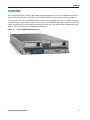
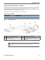
Delivering performance, versatility and density without compromise, the Cisco UCS B200 M3 Blade Server
addresses the broadest set of workloads, from IT and web infrastructure through distributed database.
The enterprise-class Cisco UCS B200 M3 blade server extends the capabilities of Cisco’s Unified Computing
System portfolio in a half-width blade form factor. The Cisco UCS B200 M3 harnesses the power of the latest
Intel® Xeon® E5-2600 v2 and E5-2600 series processor family CPUs with up to 768 GB of RAM (using 32 GB
DIMMs), 2 drives, and up to 80 Gbs throughput connectivity.
Figure 1 Cisco UCS B200 M3 Blade Server

Cisco UCS B200 M3 Blade Server
4
DETAILED VIEWS
DETAILED VIEWS
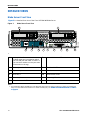
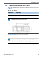
Blade Server Front View
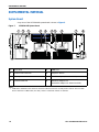
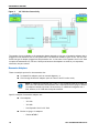
Figure 2 is a detailed front view of the Cisco UCS B200 M3 Blade Server.
Figure 2 Blade Server Front View
s
1 Asset pull handle
(a blank asset tag is provided on which
you can add your own label or sticker or
you can use a marker to write your asset
information on the tag)
7 Network link status LED
2 Blade ejector handle 8 Blade health LED
3 Ejector captive screw 9
Console connector
1
Notes...
1. For information about the KVM local I/O cable that plugs into the console connector (a cable is included with
every Cisco UCS 5100 Series blade server chassis accessory kit), see ORDER OPTIONAL KVM LOCAL I/O CABLE*
on page 35.
4 Drive bay 1 10 Reset button access
5 Drive bay 2 11 Beaconing LED and button
6 Power button and LED — —
UCS B200 M3
1 2 3
6
7
8
9
10
11
54
331360

Cisco UCS B200 M3 Blade Server
BASE SERVER STANDARD CAPABILITIES and FEATURES
5
BASE SERVER STANDARD CAPABILITIES and FEATURES
Table 1 lists the capabilities and features of the base server. Details about how to configure the server for
a particular feature or capability (for example, number of processors, disk drives, or amount of memory)
are provided in
CONFIGURING the SERVER on page 7.
NOTE: NOTE: The B200 M3 blade server requires UCS Manager (UCSM) to operate as
part of the UCS system.
■ The B200 M3 with E5-2600 CPUs requires UCSM 2.0.2(q) or later
■ The B200 M3 with E5-2600 v2 CPUs requires UCSM 2.1.3 or later
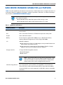
Table 1 Capabilities and Features
Capability/Feature Description
Chassis The UCS B200 M3 Blade Server mounts in a Cisco UCS 5100 series blade
server chassis
CPU One or two Intel® E5-2600 v2 or E5-2600 series processor family CPUs
Chipset Intel® C600 series chipset
Memory 24 total slots for registered ECC DIMMs for up to 768 GB total memory
capacity (B200 M3 configured with 2 CPUs using 32 GB DIMMs)
I/O Mezzanine adapters:
■ One connector for Cisco’s VIC 1240 adapter, which provides Ethernet and
Fibre Channel over Ethernet (FCoE)
■ One connector for various types of Cisco adapters, Emulex or QLogic
adapters, and Cisco UCS Storage Accelerator adapters.
Storage controller LSI Logic SAS 2004 integrated controller
■ SAS/SATA support
■ RAID 0 and 1
Internal storage devices Up to two optional, front-accessible, hot-swappable 2.5-inch small form
factor (SFF) SAS or SATA solid-state disks (SSDs) or hard disk drives (HDDs).
An internal USB 2.0 port is also supported. A 4 GB USB 2.0 device is available
from Cisco.
NOTE: The integrated RAID controller does not implement a write
cache. However, servers with two HDDs and RAID controllers with
cache lack the ability to match the performance of RAID’ed SSD
without cache, which can be configured with this server.

Cisco UCS B200 M3 Blade Server
6
BASE SERVER STANDARD CAPABILITIES and FEATURES
Video The Cisco Integrated Management Controller (CIMC) provides video:
■ Matrox G200e video controller
■ Integrated 2D graphics core with hardware acceleration
■ Supports all display resolutions up to 1920 x 1200 x 16 bpp resolution at
60 Hz
■ 24-bit color depth for all resolutions less than 1600x1200
■ Up to 256 MB video memory
Interfaces ■ Front panel
• One console connector (see ORDER OPTIONAL KVM LOCAL I/O
CABLE* on page 35)
Power subsystem Integrated in the Cisco UCS 5100 series blade server chassis
Fans Integrated in the Cisco UCS 5100 series blade server chassis
Integrated management
processor
The built-in Cisco Integrated Management Controller (CIMC) GUI or CLI
interface enables you to monitor the server inventory, health, and system
event logs.
Table 1 Capabilities and Features (continued)
Capability/Feature Description

Cisco UCS B200 M3 Blade Server
CONFIGURING the SERVER
7
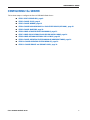
CONFIGURING the SERVER
Follow these steps to configure the Cisco UCS B200 M3 Blade Server:
■ STEP 1 VERIFY SERVER SKU, page 8
■ STEP 2 CHOOSE CPU(S), page 9
■ STEP 3 CHOOSE MEMORY, page 12
■ STEP 4 CHOOSE HARD DISK DRIVES or SOLID STATE DRIVES (OPTIONAL), page 18
■ STEP 5 CHOOSE ADAPTERS, page 20
■ STEP 6 ORDER A TRUSTED PLATFORM MODULE, page 23
■ STEP 7 ORDER CISCO FLEXIBLE FLASH SECURE DIGITAL CARDS, page 24
■ STEP 8 ORDER OPTIONAL INTERNAL USB 2.0 DRIVE, page 25
■ STEP 9 CHOOSE OPERATING SYSTEM AND VALUE-ADDED SOFTWARE, page 26
■ STEP 10 CHOOSE OPERATING SYSTEM MEDIA KIT, page 29
■ STEP 11 CHOOSE SERVICE and SUPPORT LEVEL, page 30

Cisco UCS B200 M3 Blade Server
8
CONFIGURING the SERVER
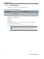
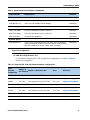
STEP 1 VERIFY SERVER SKU
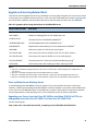
Verify the product ID (PID) of the server as shown in Table 2.
The base Cisco UCS B200 M3 blade server does not include the following components. They must
be selected during product ordering:
■ CPUs
■ Memory
■ Disk drives
■ Cisco adapters (such as the VIC 1240, VIC 1280, and Port Expander for VIC 1240)
■ Emulex and QLogic network adapters
■ Cisco UCS Storage Accelerators (such as the Fusion-io and LSI Logic adapter)
Table 2 PID of the Base UCS B200 M3 Blade Server
Product ID (PID) Description
UCSB-B200-M3 UCS B200 M3 Blade Server w/o CPU, memory, HDD, VIC 1240 adapter, or
mezzanine adapters
NOTE: Use the steps on the following pages to order servers with the
configurable components that you want configured in your servers.

Cisco UCS B200 M3 Blade Server
CONFIGURING the SERVER
9
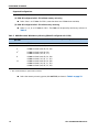
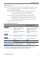
STEP 2 CHOOSE CPU(S)
The standard CPU features are:
■ Intel Xeon E5-2600 v2 and E5-2600 series processor family CPUs. See the following link for
instructions on how to upgrade your server from Intel Xeon E5-2600 to Intel Xeon E5-2600 v2
CPUs as well as how to upgrade to 1866-MHz DIMMs (supported on E5-2600 v2 CPUs):
http://www.cisco.com/en/US/docs/unified_computing/ucs/hw/CPU/IVB/install/IVB-B.html
■ Intel C600 series chipset
■ Cache size of up to 30 MB for E5-2600 v2 CPUs or 20 MB for E5-2600 CPUs
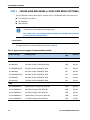
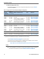
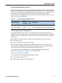
Select CPUs
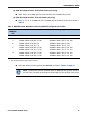
The available CPUs are listed in Table 3.
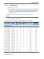
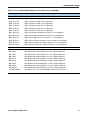
Table 3 Supported Intel CPUs: E5-2600 v2 and E5-2600 Series Processor Family CPUs
Product ID (PID)
Intel
Number
Clock
Freq
(GHz)
Power
(W)
Cache Size
(MB)
Cores QPI
Highest DDR3
DIMM Clock
Support (MHz)
1
Intel Xeon E5-2600 v2
UCS-CPU-E52697B E5-2697 v2 2.70 130W 30 12 8 GT/s 1866
UCS-CPU-E52695B E5-2695 v2 2.40 115 30 12 8 GT/s 1866
UCS-CPU-E52690B E5-2690 v2 3.00 130 25 10 8 GT/s 1866
UCS-CPU-E52680B E5-2680 v2 2.80 115 25 10 8 GT/s 1866
UCS-CPU-E52670B E5-2670 v2 2.50 115 25 10 8 GT/s 1866
UCS-CPU-E52667B E5-2667 v2 3.30 130 25 8 8 GT/s 1866
UCS-CPU-E52660B E5-2660 v2 2.20 95 25 10 8 GT/s 1866
UCS-CPU-E52658B E5-2658 v2 2.40 95 25 10 8 GT/s 1866
UCS-CPU-E52650B E5-2650 v2 2.60 95 20 8 8 GT/s 1866
UCS-CPU-E52640B E5-2640 v2 2.00 95 20 8 7.2 GT/s 1600
UCS-CPU-E52637B E5-2637 v2 3.50 130 15 4 8 GT/s 1866
UCS-CPU-E52630B E5-2630 v2 2.60 80 15 6 7.2 GT/s 1600
UCS-CPU-E52620B E5-2620 v2 2.10 80 15 6 7.2 GT/s 1600
UCS-CPU-E52643B E5-2643 v2 3.50 130 25 6 8 GT/s 1866
UCS-CPU-E52650LB E5-2650L v2 1.70 70 25 10 8 GT/s 1600
UCS-CPU-E52630LB E5-2630L v2 2.40 60 15 6 7.2 GT/s 1600
UCS-CPU-E52609B E5-2609 v2 2.50 80 10 4 6.4 GT/s 1333

Cisco UCS B200 M3 Blade Server
10
CONFIGURING the SERVER
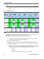
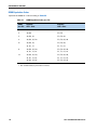
Supported Configurations
(1) One-CPU Configuration
■ Choose one CPU from any one of the rows of Table 3 on page 9.
(2) Two-CPU Configuration
■ Choose two identical CPUs from any one of the rows of Table 3 on page 9.
Caveats
■ The B200 M3 configured with 1 CPU provides limited network connectivity options. The
following restrictions apply:
— A virtual interface card (VIC), the VIC 1240, must always be installed in the VIC 1240
mezzanine connector.
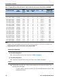
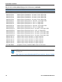
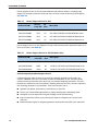
Intel Xeon E5-2600
2
UCS-CPU-E5-2690 E5-2690 2.90 135 20 8 8 GT/s 1600
UCS-CPU-E5-2680 E5-2680 2.70 130 20 8 8 GT/s 1600
UCS-CPU-E5-2670 E5-2670 2.60 115 20 8 8 GT/s 1600
UCS-CPU-E5-2667 E5-2667 2.90 130 15 6 8 GT/s 1600
UCS-CPU-E5-2665 E5-2665 2.40 115 20 8 8 GT/s 1600
UCS-CPU-E5-2660 E5-2660 2.20 95 20 8 8 GT/s 1600
UCS-CPU-E5-2658 E5-2658 2.10 95 20 8 8 GT/s 1600
UCS-CPU-E5-2650 E5-2650 2.00 95 20 8 8 GT/s 1600
UCS-CPU-E5-2650L E5-2650L 1.80 70 20 8 8 GT/s 1600
UCS-CPU-E5-2640 E5-2640 2.50 95 15 6 7.2 GT/s 1333
UCS-CPU-E5-2637 E5-2637 3.00 80 5 2 8 GT/s 1600
UCS-CPU-E5-2630 E5-2630 2.30 95 15 6 7.2 GT/s 1333
UCS-CPU-E5-2630L E5-2630L 2.00 60 15 6 7.2 GT/s 1333
UCS-CPU-E5-2620 E5-2620 2.00 95 15 6 7.2 GT/s 1333
UCS-CPU-E5-2643 E5-2643 3.30 130 10 4 8 GT/s 1600
UCS-CPU-E5-2609 E5-2609 2.40 80 10 4 6.4 GT/s 1066
Notes...
1. If higher or lower speed DIMMs are selected than what is shown in the table for a given CPU, the DIMMs will be
clocked at the lowest common denominator of CPU clock and DIMM clock.
2. 1866-MHz DIMMs are supported only with Intel Xeon E5-2600 v2 CPUs
Table 3 Supported Intel CPUs: E5-2600 v2 and E5-2600 Series Processor Family CPUs (continued)
Product ID (PID)
Intel
Number
Clock
Freq
(GHz)
Power
(W)
Cache Size
(MB)
Cores QPI
Highest DDR3
DIMM Clock
Support (MHz)
1

Cisco UCS B200 M3 Blade Server
CONFIGURING the SERVER
11
— The connectivity options are:
• VIC 1240 installed in VIC 1240 slot and no adapter installed in the mezzanine slot
• VIC 1240 installed in VIC 1240 slot and a Port Expander Card for VIC 1240
installed in the mezzanine slot.
■ See Network Connectivity on page 44 for complete information on network connectivity
support for a B200 M3 configured with 1 CPU or 2 CPUs.
■ For optimal performance, select DIMMs with the highest clock speed for a given processor.
■ System speed is dependent on how many DIMMs are populated per channel. See Table 7 on
page 16 for details.

Cisco UCS B200 M3 Blade Server
12
CONFIGURING the SERVER
STEP 3 CHOOSE MEMORY
The standard memory features are:
■ DIMMs
— Clock speed: 1866, 1600, or 1333 MHz
— Ranks per DIMM: 1, 2, or 4
— Operational voltage: 1.35 or 1.5 V
—Registered
■ DDR3 ECC registered DIMMs (RDIMMs) or load-reduced DIMMS (LRDIMMS)
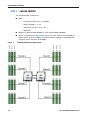
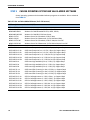
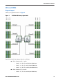
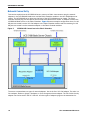
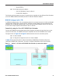
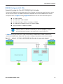
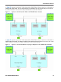
■ Memory is organized with four memory channels per CPU, with up to three DIMMs per
channel (DPC), as shown in
Figure 3. Maximum memory capacity is 768 GB (B200 M3
configured with 2 CPUs with 32 GB DIMMs).
Figure 3 UCS B200 M3 Memory Organization

Cisco UCS B200 M3 Blade Server
CONFIGURING the SERVER
13
Choose DIMMs and Memory Mirroring
Select the memory configuration and whether or not you want the memory mirroring option.
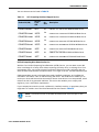
The supported memory DIMMs and the mirroring option are listed in
Table 4.
The supported memory DIMMs in the UCS B200 M3 are listed in Table 4.
NOTE: When memory mirroring is enabled, the memory subsystem simultaneously
writes identical data to two adjacent channels. If a memory read from one of the
channels returns incorrect data due to an uncorrectable memory error, the system
automatically retrieves the data from the other channel. A transient or soft error in
one channel does not affect the mirrored data, and operation continues unless there
is a simultaneous error in exactly the same location on a DIMM and its mirrored
DIMM. Memory mirroring reduces the amount of memory available to the operating
system by 50% because only one of the two populated channels provides data.
Table 4 Supported DDR3 DIMMs and Memory Mirroring Option
Product ID (PID) PID Description Voltage
Ranks
/DIMM
DIMM Options
1
Notes...
1. 1866-MHz DIMMs are supported only with Intel Xeon E5-2600 v2 CPUs.
UCS-ML-1X324RY-A 32 GB DDR3-1600-MHz LRDIMM/PC3-12800/4R/x4/1.35V
1.5/1.35 V
2
2. Dual voltage DIMM (operates at 1.5 V with BIOS is set for memory performance mode (default), or 1.35 V when
BIOS is set for power-savings mode).
4
UCS-ML-1X324RZ-A
1
32 GB DDR3-1866-MHz LRDIMM PC3-14900/4R/x4/1.5 V 1.5 V 4
UCS-MR-1X162RY-A 16 GB DDR3-1600-MHz RDIMM/PC3-12800/2R/x4/1.35V
1.5/1.35 V
2
2
UCS-MR-1X162RZ-A
1
16 GB DDR3-1866-MHz RDIMM PC3-14900/2R/x4/1.5V 1.5 V 2
UCS-MR-1X082RY-A 8 GB DDR3-1600-MHz RDIMM/PC3-12800/2R/x4/1.35V
1.5/1.35 V
2
2
UCS-MR-1X082RX-A
3
3. No longer shipping as of 11/9/2013
8 GB DDR3-1333-MHz RDIMM/PC3-10600/2R/x4/1.35v
1.5/1.35 V
2
2
UCS-MR-1X082RZ-A
1
8 GB DDR3-1866-MHz RDIMM/PC3-14900/2R/x4/1.5V 1.5 V 2
UCS-MR-1X041RY-A 4 GB DDR3-1600-MHz RDIMM/PC3-12800/1R/x4/1.35V
1.5/1.35 V
2
1
Memory Mirroring Option
N01-MMIRROR Memory mirroring option

Cisco UCS B200 M3 Blade Server
14
CONFIGURING the SERVER
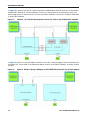
Supported Configurations
(1) B200 M3 configured with 1 CPU without memory mirroring
■ Select from 1 to 12 DIMMs for CPU 1 (note that there are 12 DIMM slots available)
(2) B200 M3 configured with 1 CPU with memory mirroring
■ Select 2, 4, 6, 8, or 12 DIMMs for CPU 1. The DIMMs will be placed by the factory as shown in
Table 5:
■ Select the memory mirroring option (N01-MMIRROR) as shown in Table 4 on page 13.
Table 5 DIMM Placement With Memory Mirroring (B200 M3 configured with 1 CPU)
Number of DIMMs
per CPU
DIMM Placement in Banks (with memory mirroring implemented)
CPU 1
2 2 DIMMs in Bank 0 (A0, B0)
4 4 DIMMs in Bank 0 (A0, B0, C0, D0)
6
1
Notes...
1. Not recommended (for performance reasons)
3 DIMMs in Bank 0 (A0, B0, C0)
3 DIMMs in Bank 1 (A1, B1, C1)
8 4 DIMMs in Bank 0 (A0, B0, C0, D0)
4 DIMMs in Bank 1 (A1, B1, C1, D1)
12 4 DIMMs in Bank 0 (A0, B0, C0, D0)
4 DIMMs in Bank 1 (A1, B1, C1, D1)
4 DIMMs in Bank 3 (A2, B2, C2, D2)

Cisco UCS B200 M3 Blade Server
CONFIGURING the SERVER
15
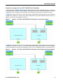
(3) B200 M3 configured with 2 CPUs without memory mirroring:
■ Select from 1 to 12 DIMMs per CPU (note that there are 12 DIMM slots per CPU)
(4) B200 M3 configured with 2 CPUs with memory mirroring:
■ Select 2, 4, 6, 8, or 12 DIMMs per CPU. The DIMMs will be placed by the factory as shown in
Table 6:
■ Select the memory mirroring option (N01-MMIRROR) as shown in Table 4 on page 13.
Table 6 DIMM Placement With Memory Mirroring (B200 M3 configured with 2 CPUs)
Number of
DIMMs per
CPU
DIMM Placement in Banks (with memory mirroring implemented)
CPU 1 CPU 2
2 2 DIMMs in Bank 0 (A0, B0) 2 DIMMs in Bank 0 (E0, F0)
4 4 DIMMs in Bank 0 (A0, B0, C0, D0) 4 DIMMs in Bank 0 (E0, F0, G0, H0)
6
1
Notes...
1. Not recommended (for performance reasons)
3 DIMMs in Bank 0 (A0, B0, C0)
3 DIMMs in Bank 1 (A1, B1, C1)
3 DIMMs in Bank 0 (E0, F0, G0)
3 DIMMs in Bank 1 (E1, F1, G1)
8 4 DIMMs in Bank 0 (A0, B0, C0, D0)
4 DIMMs in Bank 1 (A1, B1, C1, D1)
4 DIMMs in Bank 0 (E0, F0, G0, H0)
4 DIMMs in Bank 1 (E1, F1, G1, H1)
12 4 DIMMs in Bank 0 (A0, B0, C0, D0)
4 DIMMs in Bank 1 (A1, B1, C1, D1)
4 DIMMs in Bank 2 (A2, B2, C2, D2)
4 DIMMs in Bank 0 (E0, F0, G0, H0)
4 DIMMs in Bank 1 (E1, F1, G1, H1)
4 DIMMs in Bank 2 (E2, F2, G2, H2)
NOTE: System performance is optimized when the DIMM type and quantity are equal
for both CPUs, and when all channels are filled equally across the CPUs in the server.

Cisco UCS B200 M3 Blade Server
16
CONFIGURING the SERVER
Caveats
■ System speed is dependent on how many DIMMs are populated per channel. See Table 7 for
details.
■ For optimum performance, do not mix DIMMs with different frequencies. If you mix DIMM
frequencies, the system defaults to the lower frequency.
■ Do not mix RDIMMs with LRDIMMs
■ DIMMs for CPU 1 and CPU 2 (when populated) must always be configured identically.
■ Memory mirroring reduces the amount of available memory by 50% (quantity of DIMMs must
be even for mirroring).
■ By default, starting with UCSM 2.0.4, DIMMs run in memory performance mode (1.5v) by
BIOS default, which yields faster memory speeds than when the BIOS is set for the memory
to run in power-savings mode. Memory speed is dependent on factors such as:
— CPU choice
— DIMM choice
— DIMM population (how many DIMMs per channel are populated)
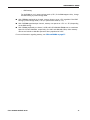
Table 7 DIMM Memory Speeds
DIMM
Speed
DPC
1333-MHz Capable CPU 1600-MHz Capable CPU 1866-MHz Capable CPU
LRDIMM
RDIMM
(DR, SR)
LRDIMM
RDIMM
(DR, SR)
LRDIMM
RDIMM
(DR, SR)
1.3 V 1.5 V 1.3 V 1.5 V 1.3 V 1.5 V 1.3 V 1.5 V 1.3 V 1.5 V 1.3 V 1.5 V
1333
DIMM
1DPC 1333 1333 1333 1333 1333 1333 1333 1333 1333 1333 1333 1333
2DPC 1333 1333 1333 1333 1333 1333 1333 1333 1333 1333 1333 1333
3DPC 1066 1066
NA
1
Notes...
1. NA = not applicable
1066 1066 1066
NA
1
1066 1066 1066
NA
1
1066
1600
DIMM
1DPC 1333 1333 1333 1333
1600
2
2. These DIMMs operate at 1333 MHz instead of 1600 MHz when used with any E5-2600 CPUs. They operate at 1600
MHz when used with E5-2600 v2 CPUs that support 1600- and 1866-MHz speeds.
1600
2
1333 1600
1600
2
1600
2
1333 1600
2DPC 1333 1333 1333 1333
1600
2
1600
2
1333 1600
1600
2
1600
2
1333 1600
3DPC 1066 1066
NA
1
1066 1066 1066
NA
1
16 GB -1333
8 GB - 1066
1066 1066
NA
1
16 GB -1333
8 GB - 1066
1866
DIMM
3
3. 1866-MHz DIMMs are only offered and supported with E5-2600 v2 CPU-configured servers
1DPC
NA
1
1333
NA
1
1333
NA
1
1600
NA
1
1600
NA
1
1866
NA
1
1866
2DPC
NA
1
1333
NA
1
1333
NA
1
1600
NA
1
1600
NA
1
1866
NA
1
1866
3DPC
NA
1
1066
NA
1
1066
NA
1
1066
NA
1
1333
NA
1
1333
NA
1
1333

Cisco UCS B200 M3 Blade Server
CONFIGURING the SERVER
17
— BIOS setting.
For the DIMMs to run in power-savings mode (1.35 V, if the DIMM supports this), change
the BIOS setting to power-savings mode.
■ With 3 RDIMMs populated per channel, memory always runs at 1.5 V regardless if the BIOS
setting is power-savings mode (1.35 V) or performance mode (1.5 V).
■ With 3 LRDIMMs populated per channel, memory can operate at 1.5 V or 1.35 V, depending
on the BIOS setting.
■ With 3 DIMMs populated per channel, 16 GB and 8 GB 1600-MHz RDIMMs run at a maximum
speed of 1333 and 1066 MHz, respectively (for 1600- and 1866-MHz CPUs). Other memory
devices are limited to 1066 MHz operation when populated at 3 DPC.
For more information regarding memory, see CPUs and DIMMs on page 37.

Cisco UCS B200 M3 Blade Server
18
CONFIGURING the SERVER
STEP 4 CHOOSE HARD DISK DRIVES or SOLID STATE DRIVES (OPTIONAL)
The UCS B200 M3 can be ordered with or without drives. The standard disk drive features are:
■ 2.5-inch small form factor
■ Hot-pluggable
■ Sled-mounted
Choose Drives
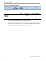
The supported drives in the UCS B200 M3 are listed in Table 8.
NOTE: The UCS B200 M3 blade server meets the external storage target and switch
certifications as described in the following link:
http://www.cisco.com/en/US/docs/switches/datacenter/mds9000/interoperabilit
y/matrix/Matrix8.html#wp323852
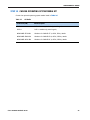
Table 8 Supported Hot-Pluggable Sled-Mounted HDDs and SSDs
Product ID (PID) PID Description
Drive
Type
Capacity
HDDs
A03-D1TBSATA 1 TB 6 Gb SATA 7.2K RPM SFF HDD SATA 1 TB
A03-D500GC3 500 GB 6 Gb SATA 7.2K RPM SFF HDD SATA 500 GB
UCS-HDD900GI2F106 900 GB 6 Gb SAS 10K RPM SFF HDD SAS 900 GB
A03-D600GA2 600 GB 6 Gb SAS 10K RPM SFF HDD SAS 600 GB
UCS-HDD300GI2F105 300 GB 6 Gb SAS 15K RPM SFF HDD SAS 300 GB
A03-D300GA2 300 GB 6 Gb SAS 10K RPM SFF HDD SAS 300 GB
A03-D146GC2 146 GB 6 Gb SAS 15K RPM SFF HDD SAS 146 GB
SSDs
UCS-SD400G0KA2-G 400GB SATA 2.5" Enterprise Value SSD SATA 400 GB
UCS-SD300G0KA2-E 300 GB Std Height 15mm SATA SSD SATA 300 GB
UCS-SD200G0KA2-E 200 GB Std Height 15mm SATA SSD SATA 200 GB
UCS-SD100G0KA2-G 100GB SATA 2.5" Enterprise Value SSD SATA 100 GB
UCS-SD100G0KA2-E 100 GB Std Height 15mm SATA SSD SATA 100 GB

Cisco UCS B200 M3 Blade Server
CONFIGURING the SERVER
19
Supported Configurations
(1) 1-Drive System
■ Select one of the drives listed in Table 8.
(1) 2-Drive System
■ Select two identical drives from Table 8. There is no support for mixing of drive types or
capacities.
Caveats
■ If you select two drives, they must be identical in type and capacity.
NOTE: The integrated RAID controller supports hard disk drives (HDDs) or solid state
drives (SSDs). Write cache is not implemented. SSDs are recommended for
applications requiring high-speed local storage, which is an order of magnitude
faster than HDDs.

Cisco UCS B200 M3 Blade Server
20
CONFIGURING the SERVER
STEP 5 CHOOSE ADAPTERS
The adapter offerings are:
■ Cisco Virtual Interface Cards (VICs)
Cisco developed Virtual Interface Cards (VICs) to provide flexibility to create multiple NIC and
HBA devices. The VICs also support adapter Fabric Extender and Virtual Machine Fabric Extender
technologies.
■ Converged Network Adapters (CNAs)
Emulex and QLogic Converged Network Adapters (CNAs) consolidate Ethernet and Storage (FC)
traffic on the Unified Fabric by supporting FCoE.
■ Cisco UCS Storage Accelerator Adapters
Cisco UCS Storage Accelerator adapters are designed specifically for the Cisco UCS B-series M3
blade servers and integrate seamlessly to allow improvement in performance and relief of I/O
bottlenecks.
Choose a Mezzanine Adapter
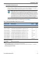
The supported mezzanine adapters in the UCS B200 M3 are listed in Table 9.
NOTE: There are two slots on the server. One accommodates Cisco, Emulex, and
QLogic I/O adapters or Cisco Storage Accelerator adapters as well as other options,
and one is a dedicated slot for the VIC 1240 adapter only.
Table 9 shows which
adapters plug into each of the two slots. Only the VIC 1240 adapter plugs into the VIC
1240 adapter slot. All other adapters plug into the mezzanine adapter slot.
NOTE: You must have a B200 M3 configured with 2 CPUs to support cards that plug
into the mezzanine connector. The VIC 1240 adapter is supported on both 1- and
2-CPU configured systems.
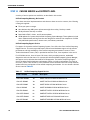
Table 9 Supported Mezzanine Adapters
Product ID (PID) PID Description Connector
Virtual Interface Cards (VICs)
UCSB-MLOM-40G-01 Cisco UCS VIC 1240 adapter for M3 blade servers. Plugs into the
dedicated VIC 1240 slot only. This is the only adapter that can
be plugged into the slot.
VIC 1240
UCS-VIC-M82-8P Cisco UCS VIC 1280 dual 40Gb capable Virtual Interface Card Mezzanine
Page is loading ...
Page is loading ...
Page is loading ...
Page is loading ...
Page is loading ...
Page is loading ...
Page is loading ...
Page is loading ...
Page is loading ...
Page is loading ...
Page is loading ...
Page is loading ...
Page is loading ...
Page is loading ...
Page is loading ...
Page is loading ...
Page is loading ...
Page is loading ...
Page is loading ...
Page is loading ...
Page is loading ...
Page is loading ...
Page is loading ...
Page is loading ...
Page is loading ...
Page is loading ...
Page is loading ...
Page is loading ...
Page is loading ...
Page is loading ...
Page is loading ...
Page is loading ...
Page is loading ...
Page is loading ...
Page is loading ...
Page is loading ...
Page is loading ...
Page is loading ...
-
 1
1
-
 2
2
-
 3
3
-
 4
4
-
 5
5
-
 6
6
-
 7
7
-
 8
8
-
 9
9
-
 10
10
-
 11
11
-
 12
12
-
 13
13
-
 14
14
-
 15
15
-
 16
16
-
 17
17
-
 18
18
-
 19
19
-
 20
20
-
 21
21
-
 22
22
-
 23
23
-
 24
24
-
 25
25
-
 26
26
-
 27
27
-
 28
28
-
 29
29
-
 30
30
-
 31
31
-
 32
32
-
 33
33
-
 34
34
-
 35
35
-
 36
36
-
 37
37
-
 38
38
-
 39
39
-
 40
40
-
 41
41
-
 42
42
-
 43
43
-
 44
44
-
 45
45
-
 46
46
-
 47
47
-
 48
48
-
 49
49
-
 50
50
-
 51
51
-
 52
52
-
 53
53
-
 54
54
-
 55
55
-
 56
56
-
 57
57
-
 58
58


Cisco UCS-CPU-E52609BC= Datasheet
- Category
- Processors
- Type
- Datasheet
Ask a question and I''ll find the answer in the document
Finding information in a document is now easier with AI
Related papers
-
Cisco UCS-CPU-E52660BC= User manual
-
Cisco UCS B200 M4 Installation And Service Note
-
Cisco UCS B22 M3 User manual
-
-
-
-
-
-
Cisco UCSC-PCIE-BTG= Datasheet
-
Other documents
-
Schonbek 1240-26S Operating instructions
-
Cisco Systems Computer Drive A03D600GA2 User manual
-
-
-
-
Kensington K38066 User manual
-
-
Hewlett Packard Enterprise D9Y42A User manual
-
-