Joy-it Joy-IT Sensor Education Set Storage Case Breadboard Sensors User manual

Type
User manual

This manual is also suitable for

The Joy-it Joy-IT Sensor Education Set Storage Case Breadboard Sensors is a comprehensive kit designed to empower users to explore the world of sensors and electronics. It includes a variety of sensors, a breadboard, and a storage case, making it ideal for educational purposes, hobbyists, or anyone interested in DIY projects. With this kit, you can build and experiment with various circuits, measure environmental parameters, and create interactive projects.

The Joy-it Joy-IT Sensor Education Set Storage Case Breadboard Sensors is a comprehensive kit designed to empower users to explore the world of sensors and electronics. It includes a variety of sensors, a breadboard, and a storage case, making it ideal for educational purposes, hobbyists, or anyone interested in DIY projects. With this kit, you can build and experiment with various circuits, measure environmental parameters, and create interactive projects.

SENSOR EDUCATION SET
Joy-IT powered by SIMAC Electronics GmbH - Pascalstr. 8 - 47506 Neukirchen-Vluyn - www.joy-it.net
Dear Customer,
Thank you for choosing our product. In the following, we will show you what
you should pay attention to during commissioning and use.
Should you encounter any unexpected problems during use, please feel free
to contact us.
This high quality sensor kit is specially designed for the most popular open
source platforms in Germany.
It is compatible with the following single board computers:
Raspberry (all models), Arduino, Banana PI, Cubieboard, Cubietruck,
Beaglebone, pcDuino and the microcontrollers (atmega, AVR, MicroChip
PIC, STM32 etc.).
For Raspberry Pi and Arduino, we provide detailed instructions
below. It contains a description of the respective sensors, the
pinout as well as a programming example for Raspberry and
Arduino. Through this, even programming beginners and students can
easily develop and carry out their own tests, projects and experiments.
So you have in no time at all the possibility to check your heartbeat
or measure the room temperature and humidity in your environment.
measure. Especially for the Raspberry Pi, the set includes an Analog-Digital
converter and a voltage translator. You can either solder the sensors
solder the sensors or put them on a breadboard to work on dierent
circuits or experiments.
1. GENERAL INFORMATION
2. BASICS
With the help of the breadboard, user-dened circuits can be designed
easily and clearly.
The rst and last 30 columns + and - are connected vertically. The rows are
connected from A to E and from F to J horizontally.
These interconnected columns and rows are marked in green here.
3. THE BREADBOARD
The high-quality SensorKit X40 was specially developed for operation
with the most popular open source platforms. It is compatible with
single board computers (Arduino, Raspberry Pi, Banana Pi, Cubieboard,
Cubietruck, Beaglebone, pcDuino) and microcontrollers (atmega, AVR,
MicroCHip PIC, STM32 etc.).
The kit consists of a total of 40 dierent sensors which are either can
be soldered or plugged on a breadboard to work on dierent circuits or work
on dierent circuits or experiments.
Detailed instructions with code examples for each of the components
included in the sensor kit, for both Arduino and Raspberry Pi, can be found
at the following link:
sensorkit.joy-it.net
4. SENSORKIT X40
The GP2Y1014AU is an optical sensor for the detection of dust particles.
By means of an integrated infrared diode and a phototransistor, the light
reected by the dust is detected and can thus be determined in an analog
value.
5.1 USE WITH THE RASPBERRY PI
Since the dust sensor is an analog sensor and the Raspberry Pi has no analog
inputs, you have to use the analog to digital converter from the sensor kit (KY-
053).
5.1.1 CONNECTION
Connect the sensor to your Raspberry Pi as shown in the following picture and
table.
5. GP2Y1014AU - OPTICAL DUST SENSOR
5.1.2 INSTALLATION
To be able to use the Analog to Digital Converter, you must install the required
library. To do this, open the terminal and enter the following command:
Now enable the I2C interface by opening the Raspberry Pi conguration
menu using the following command:
Select here the option Interfacing Options and activate there the I2C
interface.
The analog-digital converter is now ready for use. Now create a new program
le with the following command:
Now copy the following sample code completely into the le you just created:
GND (Pin 6)
GND (Pin 14)
GND
GND
BCM17 (Pin 11)
SCL (Pin 5)
SDA (Pin 3)
3V3 (Pin 1)
A0
3V3 (Pin 17)
LED
SCL
SDA
VCC
Out
VDD
RASPBERRY PI
KY-053 ADC
RASPBERRY PI
GP2Y1014AU
GP2Y1014AU
KY-053 ADC
sudo pip3 install adafruit-circuitpython-ads1x15
sudo raspi-cong
sudo nano gp2y.py
#!/usr/bin/python
# coding=utf-8
import time
import board
import busio
import adafruit_ads1x15.ads1115 as ADS
from adafruit_ads1x15.analog_in import AnalogIn
import RPi.GPIO as GPIO
GPIO.setmode(GPIO.BCM)
LED_Pin = 17
GPIO.setup(LED_Pin, GPIO.OUT)
# Create the I2C bus
i2c = busio.I2C(board.SCL, board.SDA)
# Create the ADC object using the I2C bus
ads = ADS.ADS1115(i2c)
# Create single-ended input on channels
chan0 = AnalogIn(ads, ADS.P0)
chan1 = AnalogIn(ads, ADS.P1)
chan2 = AnalogIn(ads, ADS.P2)
chan3 = AnalogIn(ads, ADS.P3)
while True:
GPIO.output(LED_Pin, False)
time.sleep(0.000280)
dustVal=chan0.value
time.sleep(0.000040)
GPIO.output(LED_Pin, True)
time.sleep(0.009680)
time.sleep(1)
if (dustVal>36.455):
print(((dustVal/1024)-0.0356)*120000*0.035)
Now save the le with the key combination CTRL + O, conrm with Enter
and exit the le with the combination CTRL + X. You can now execute the
program with the following command:
sudo python3 gp2y.py
5.2 USE WITH THE ARDUINO
In the following explanaons and illustraons we use an Arduino Uno. Howe-
ver, you can also easily use another Arduino can be used.
5.2.1 CONNECTION
Connect the sensor to your Arduino as shown in the following picture and
table.
GND GND
D2
A0
5 V
LED
Out
VCC
ARDUINO GP2Y1014AU
5.2.2 INSTALLATION
For programming the Arduino we recommend the Arduino IDE. You can
download and install it here. Then copy the following code example in your
Arduino IDE and transfer it to your Arduino.
int dustPin=0;
oat dustVal=0;
int ledPower=2;
int delayTime=280;
int delayTime2=40;
oat oTime=9680;
void setup(){
Serial.begin(9600);
pinMode(ledPower,OUTPUT);
pinMode(dustPin, INPUT);
}
void loop(){
digitalWrite(ledPower,LOW);
delayMicroseconds(delayTime);
dustVal=analogRead(dustPin);
delayMicroseconds(delayTime2);
digitalWrite(ledPower,HIGH);
delayMicroseconds(oTime);
delay(1000);
if (dustVal>36.455)
Serial.println((oat(dustVal/1024)-0.0356)*120000*0.035);
The CCS811 is a gas sensor used to monitor air quality and can measure a
wide range of volatile organic compounds (VOC). The sensor's data can be
converted to a total volatile organic compound (TVOC) or carbon dioxide
equivalent (eCO2) level.
The module also has a metal oxide (MOX) sensor and the option to connect
an NTC for temperature measurement.
6.1 USE WITH THE RASPBERRY PI
6.1.1 CONNECTION
Connect the sensor to your Raspberry Pi as shown in the following picture and
table.
6. CCS811 - AIR QUALITY SENSOR
GND (Pin 6) GND
SCL (Pin 5)
SDA (Pin 3)
GND (Pin 14)
3V3 (Pin 1)
SCL
SDA
Wake
VCC
RASPBERRY PI CCS811
6.1.2 INSTALLATION
To be able to use the sensor, you must rst install the required libraries.
To do this, open the terminal and enter the following commands:
Additionally now the I2C baud rate must be reduced. Open your cong.txt
le with the following command:
Now save the le with the key combination Ctrl + O, conrm with Enter and
exit the editor with Ctrl + X.
Now that the sensor has been connected and the required libraries have
been installed, the program le can be created:
Add the following line to the end of the le:
Copy the following sample code in its entirety into the le you just created:
Now save the le and run it with the following command:
sudo apt-get update
sudo apt-get upgrade
sudo pip3 install adafruit-circuitpython-ccs811
sudo apt-get install -y build-essential python-pip python-dev python-smbus git
git clone https://github.com/adafruit/Adafruit_Python_GPIO.git
cd Adafruit_Python_GPIO
sudo python setup.py install
import time
import board
import busio
import adafruit_ccs811
i2c = busio.I2C(board.SCL, board.SDA)
ccs811 = adafruit_ccs811.CCS811(i2c)
# Wait for the sensor to be ready and calibrate the thermistor
while not ccs811.data_ready:
pass
temp = ccs811.temperature
ccs811.temp_oset = temp - 25.0
while True:
print("CO2: {} PPM, TVOC: {} PPM, Temp: {} C"
.format(ccs811.eco2, ccs811.tvoc, ccs811.temperature))
time.sleep(0.5)
sudo nano /boot/cong.txt
dtparam=i2c_baudrate_10000
sudo nano ccs811.py
sudo python3 ccs811.py
6.2 USE WITH THE ARDUINO
6.2.1 CONNECTION
Connect the sensor to your Arduino as shown in the following picture and
table.
6.2.2 INSTALLATION
To be able to use the sensor, you must rst install the required install the
required library. To do this, open the Arduino IDE and click on Sketch ->
Include Library -> Manage Libraries.
GND GND
SCL (A5)
SDA (A4)
GND
5 V
SCL
SDA
Wake
VCC
ARDUINO CCS811
Now enter CCS811 in the window that opens and install the Adafruit CCS811
Library by Adafruit.
Now copy the following code example into your Arduino IDE and transfer it to
your Arduino.
/***************************************************************************
This is a library for the CCS811 air
This sketch reads the sensor
Designed specically to work with the Adafruit CCS811 breakout
----> http://www.adafruit.com/products/3566
These sensors use I2C to communicate. The device's I2C address is 0x5A
Adafruit invests time and resources providing this open source code,
please support Adafruit andopen-source hardware by purchasing products
from Adafruit!
Written by Dean Miller for Adafruit Industries.
BSD license, all text above must be included in any redistribution
***************************************************************************/
#include "Adafruit_CCS811.h"
Adafruit_CCS811 ccs;
void setup() {
Serial.begin(9600);
Serial.println("CCS811 test");
if(!ccs.begin()){
Serial.println("Failed to start sensor! Please check your wiring.");
while(1);
}
//calibrate temperature sensor
while(!ccs.available());
oat temp = ccs.calculateTemperature();
ccs.setTempOset(temp - 25.0);
}
void loop() {
if(ccs.available()){
oat temp = ccs.calculateTemperature();
if(!ccs.readData()){
Serial.print("CO2: ");
Serial.print(ccs.geteCO2());
Serial.print("ppm, TVOC: ");
Serial.print(ccs.getTVOC());
Serial.print("ppb Temp:");
Serial.println(temp);
}
else{
Serial.println("ERROR!");
while(1);
}
}
delay(500);
}
7. INFORMATION & TAKE-BACK OBLIGATIONS
Our information and take-back obligations under the Electrical
and Electronic Equipment Act (ElektroG)
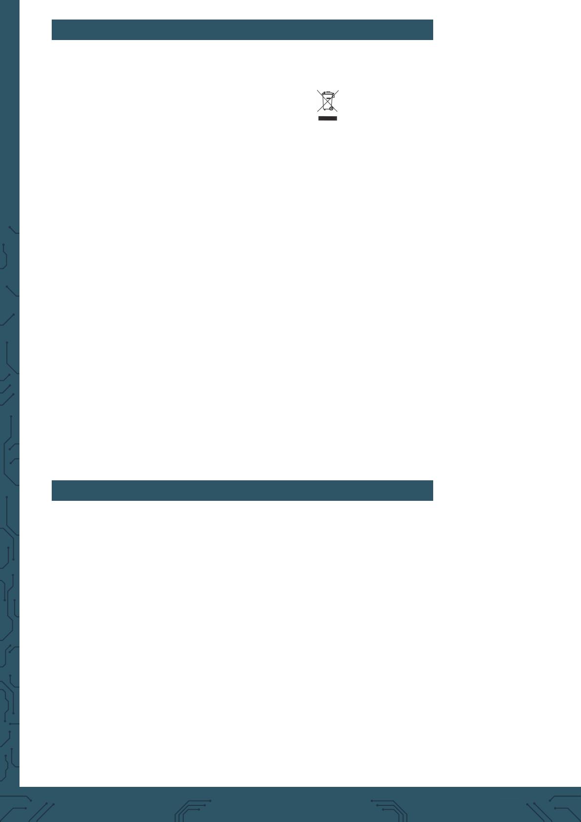
Symbol on electrical and electronic equipment:
This crossed-out trash can means that electrical and electronic equipment
does not belong in the household trash. You must hand in the old equipment
at a collection point. Before handing in, you must separate used batteries
and accumulators that are not enclosed in the old device from the old device.
Return options:
As an end user, when you purchase a new appliance, you can return your
old appliance (which performs essentially the same function as the new one
purchased from us) for disposal free of charge. Small appliances with no
external dimensions larger than 25 cm can be returned in normal household
quantities, regardless of the purchase of a new appliance.
Possibility return to our company location during opening hours:
SIMAC Electronics GmbH, Pascalstr. 8, D-47506 Neukirchen-Vluyn
Possibility return in your area:
We will send you a parcel stamp with which you can return the device to us
free of charge. To do this, please contact us by e-mail at [email protected]t
or by phone.
Packaging information:
Please pack your old device securely for transport. If you do not have
suitable packaging material or do not wish to use your own, please contact
us and we will send you suitable packaging.
www.joy-it.net
SIMAC Electronics GmbH
Pascalstr. 8 47506 Neukirchen-Vluyn
Published: 27.12.2022
8. SUPPORT
We are also there for you aer the purchase. If any questions remain or
problems arise, we are also available to assist you via email, phone and
ticket support system.
E-Mail: service@joy-it.net
Ticket-System: http://support.joy-it.net
Phone: +49 (0)2845 9360 – 50 (9:30 - 17:15 Uhr)
For more information, visit our website:
www.joy-it.net
  • Page 1 1
  • Page 2 2
  • Page 3 3
  • Page 4 4
  • Page 5 5
  • Page 6 6
  • Page 7 7
  • Page 8 8
  • Page 9 9
  • Page 10 10
  • Page 11 11
  • Page 12 12
  • Page 13 13
  • Page 14 14

Joy-it Joy-IT Sensor Education Set Storage Case Breadboard Sensors User manual

Type
User manual
This manual is also suitable for

The Joy-it Joy-IT Sensor Education Set Storage Case Breadboard Sensors is a comprehensive kit designed to empower users to explore the world of sensors and electronics. It includes a variety of sensors, a breadboard, and a storage case, making it ideal for educational purposes, hobbyists, or anyone interested in DIY projects. With this kit, you can build and experiment with various circuits, measure environmental parameters, and create interactive projects.

Ask a question and I''ll find the answer in the document

Finding information in a document is now easier with AI