Page is loading ...

Operating
Instructions
Fronius Primo GEN24
3.0 / 3.0 Plus / 3.6 / 3.6 Plus
4.0 / 4.0 Plus / 4.6 / 4.6 Plus
5.0 / 5.0 Plus / 6.0 / 6.0 Plus
42,0426,0302,EN 014-02082022
EN Operating Instructions


Contents
Safety rules 8
Explanation of safety notices 8
Safety 8
General 8
Environmental conditions 9
Qualified personnel 9
Noise emission values 9
EMC measures 10
Backup power 10
Data protection 11
Copyright 11
Protective earthing (PE) 11
General information 13
Fronius Primo GEN24 15
Device concept 15
Function overview 15
Fronius UP 16
Scope of supply 16
Intended use 16
Thermal concept 17
Fronius Solar.web 17
The various operating modes 19
Operating modes – Explanation of symbols 19
Operating mode – Inverter with battery 20
Operating mode – Inverter with battery and several Smart Meters 20
Operating mode - inverter with battery, AC-coupled to another inverter 21
Operating mode – Inverter with battery and backup power function 21
Operating mode – Inverter with battery, Ohmpilot and backup power function 21
Operating mode – Inverter with battery, further inverter and backup power function 22
Energy flow direction of the inverter 22
Operating states (only for systems with a battery) 23
Energy saving mode 24
General 24
Switch-off conditions 24
Switch-on conditions 24
Special case 24
Indication of energy saving mode 25
Suitable batteries 26
General 26
Limitations in operation 26
BYD Battery-Box Premium 26
Protection of people and equipment 28
Central grid and system protection 28
WSD (wired shutdown) 28
RCMU 28
Surge protective device 28
Control elements and connections 29
Connection area 29
Connection area divider 30
Ground electrode terminal 30
DC disconnector 31
Data communication area 31
Internal schematic connection diagram of the IOs 32
Backup power variant - PV Point (OP) 35
General 37
PV Point (OP) 37
3
EN

Explanation - PV Point (OP) 37
Backup power variant - Full Backup 39
General 41
Prerequisites for backup power mode 41
Transitioning from feeding energy into the grid to backup power mode 41
Transitioning from backup power mode to feeding energy into the grid 41
Backup power and energy saving mode 42
Cabling variants including backup power circuits with 1-pin separation e.g. Austria or Aus-
tralia
43
Functions 43
Transitioning from feeding energy into the grid to backup power mode 43
Transitioning from backup power mode to feeding energy into the grid 43
All-pin separation cabling variant, e.g. Germany, France, Spain, UK 44
Functions 44
Transitioning from feeding energy into the grid to backup power mode 44
Transitioning from backup power mode to feeding energy into the grid 45
All-pin split separation cabling variant (Italy) 46
Functions 46
Transitioning from feeding energy into the grid to backup power mode 46
Transitioning from backup power mode to feeding energy into the grid 47
Installation 49
General 51
Quick-lock system 51
Warning notices on the device 51
System component compatibility 53
Installation location and position 54
Choosing the location of the inverter 54
Choosing the location of third-party batteries 55
Explanation of symbols for the installation position 56
Install the mounting bracket and hang up the inverter 58
Selecting the fixing material 58
Properties of the mounting bracket 58
Do not deform the mounting bracket 58
Fitting the mounting bracket to a wall 58
Installing the mounting bracket on a mast or beam 59
Attaching the mounting bracket to mounting rails 60
Attaching the inverter to the mounting bracket 60
Prerequisites for connecting the inverter 61
Permitted cables 61
Permitted cables for the data communication area 62
Cross section of the AC cable 62
Cross section of the DC cable 63
Maximum alternating current fuse protection 63
Connecting the inverter to the public grid (AC side) 65
Safety 65
Connecting the inverter to the public grid (AC side) 65
Connecting solar module strings to the inverter 68
General comments regarding solar modules 68
Safety 68
PV generator - general information 69
PV generator configuration 3 ‑ 6 kW 69
Connecting the solar module strings to the inverter 70
Connecting the battery to the inverter 74
Safety 74
Connecting the battery on the DC side 74
Connecting backup power - PV Point (OP) 79
Safety 79
Installation 79
Connecting backup power - Full Backup 84
4

Safety 84
Cabling variants including backup power circuits with 1-pin separation e.g. Austria or Aus-
tralia
84
All-pin separation cabling variant e.g. Germany, France, Spain 85
All-pin separation cabling variant, e.g. UK 86
All-pin separation cabling variant, e.g. Italy 87
Testing backup power mode 88
Connecting the data communication cable 89
Modbus participants 89
Routing data communication cables 90
Connecting the battery communication cables 92
Terminating resistors 92
Installing the WSD (wired shutdown) 94
Closing and commissioning the inverter 95
Closing the inverter's connection area/housing cover, and commissioning 95
Starting the inverter for the first time 95
Button functions and LED status indicator 96
Installation with the app 97
Installation using the web browser 98
Switching off current supply and restarting the inverter 100
De-energising the inverter and switching it on again 100
Settings - user interface of the inverter 101
User settings 103
User login 103
Selecting the language 103
Device configuration 104
Components 104
Functions andI/Os 105
Demand Response Modes (DRM) 106
Inverter 106
Energy management 110
Energy management 110
Examples - Time-dependent battery control 111
Allowed battery control rules 113
PV power reduction 115
Load management 115
System 117
General 117
Update 117
Setup wizard 117
Restoring the factory settings 117
Event Log 117
Information 117
Licence manager 118
Support 119
Communication 120
Network 120
Modbus 121
Fronius Solar API 122
Safety and grid requirements 123
Country setup 123
Feed-in limitation 123
Dynamic power regulation with several inverters 125
I/O power management 127
Connection diagram - 4 relay 128
I/O power management settings - 4 relays 129
Connection diagram - 3 relay 130
I/O power management settings - 3 relays 131
Connection diagram - 2 relay 132
I/O power management settings - 2 relays 133
5
EN

Connection diagram - 1 relay 134
I/O power management settings - 1 relay 135
Autotest(CEI 0-21) 135
Options 137
Surge protective device (SPD) 139
General 139
Scope of supply 139
De-energising the inverter 139
Installation 140
Commissioning the inverter 146
Appendix 149
Care, maintenance and disposal 151
General 151
Cleaning 151
Maintenance 151
Safety 151
Operation in dusty environments 151
Disposal 152
Guarantee provisions 154
Fronius manufacturer's warranty 154
Components for automatic Full Backup backup power changeover 155
Components for automatic Full Backup backup power changeover 155
Status codes and remedy 157
Display 157
Status Codes 157
Technical data 158
Fronius Primo GEN24 3.0 / 3.0 Plus 158
Fronius Primo GEN24 3.6 / 3.6 Plus 161
Fronius Primo GEN24 4.0 / 4.0 Plus 164
Fronius Primo GEN24 4.6 / 4.6 Plus 167
Fronius Primo GEN24 5.0 / 5.0 Plus 170
Fronius Primo GEN24 6.0 / 6.0 Plus 173
Technical data of surge protective device DC SPD type 1+2 GEN24 176
Explanation of footnotes 176
Integrated DC disconnector 176
Circuit diagrams 179
Circuit Diagram - PV Point (OP) 181
Circuit Diagram 181
Fronius Primo GEN24 and BYD Battery-Box Premium HV 182
Circuit Diagram 182
Fronius Primo GEN24 with two BYD Battery-Box Premium HV connected in parallel 183
Circuit Diagram 183
Fronius Primo GEN24 with three BYD Battery-Box Premium HV connected in parallel 184
Circuit Diagram 184
Automatic switch to backup power 1-pin double separation - e.g. Austria 185
Circuit Diagram 185
Automatic switch to backup power 1-pin single separation - e.g. Australia 186
Circuit Diagram 186
Automatic switch to backup power 2-pin double separation - e.g. Germany 187
Circuit Diagram 187
Automatic switch to backup power 2-pin single separation - e.g. France, Spain 188
Circuit Diagram 188
Automatic switch to backup power 2-pin double separation - e.g. UK 189
Circuit Diagram 189
Automatic switch to backup power 2-pin double separation with ext. grid and system protec-
tion - e.g. Italy
190
Circuit Diagram 190
Fronius Primo GEN24 with Enwitec Box 191
6


Safety rules
Explanation of
safety notices WARNING!
Indicates a potentially hazardous situation.
▶If not avoided, death or serious injury may result.
CAUTION!
Indicates a situation where damage could occur.
▶If not avoided, minor injury and/or damage to property may result.
NOTE!
Indicates a risk of flawed results and possible damage to the equipment.
If you see any of the symbols depicted in the "Safety rules" chapter, special care
is required.
Safety CAUTION!
Danger from crushing due to the incorrect handling of attachments and con-
nection parts.
Injuries to limbs may result.
▶When lifting up, putting down and attaching the inverter, use the integrated
grips.
▶When fitting attachments, ensure that no limbs are located between the at-
tachment and the inverter.
▶Do not hold onto the individual poles on the terminals when locking and un-
locking.
General The device has been manufactured in line with the state of the art and according
to recognised safety standards. In the event of incorrect operation or misuse,
there is a risk of
-Injury or death to the operator or a third party
-Damage to the device and other material assets belonging to the operating
company
All personnel involved in commissioning, maintenance, and servicing of the
device must:
-Be suitably qualified
-Have knowledge of and experience in dealing with electrical installations
-Have fully read and precisely followed these Operating Instructions
In addition to the Operating Instructions, all applicable local rules and regula-
tions regarding accident prevention and environmental protection must also be
followed.
8

All safety and danger notices on the device:
-Must be kept in a legible state
-Must not be damaged
-Must not be removed
-Must not be covered, pasted, or painted over
Only operate the device when all protection devices are fully functional. If the
protection devices are not fully functional, there is a danger of
-Injury or death to the operator or a third party
-Damage to the device and other material assets belonging to the operating
company
Any safety devices that are not fully functional must be repaired by an author-
ized specialist before the device is switched on.
Never bypass or disable protection devices.
For the location of the safety and danger notices on the device, refer to the
chapter headed "Warning notices on the device" in the Operating Instructions for
your device.
Faults that could compromise safety must be remedied before switching on the
device.
Environmental
conditions
Operation or storage of the device outside the stipulated area will be deemed as
not in accordance with the intended purpose. The manufacturer accepts no liab-
ility for any damage resulting from improper use.
Qualified per-
sonnel
The servicing information contained in these operating instructions is intended
only for the use of qualified service engineers. An electric shock can be fatal. Do
not carry out any actions other than those described in the documentation. This
also applies to qualified personnel.
All cables and leads must be secured, undamaged, insulated and adequately di-
mensioned. Loose connections, scorched, damaged or inadequately dimensioned
cables and leads must be immediately repaired by authorised personnel.
Maintenance and repair work must only be carried out by an authorised special-
ist.
It is impossible to guarantee that bought-in parts are designed and manufac-
tured to meet the demands made on them, or that they satisfy safety require-
ments. Use only original spare parts (also applies to standard parts).
Do not carry out any alterations, installations, or modifications to the device
without first obtaining the manufacturer's permission.
Components that are not in perfect condition must be changed immediately.
Noise emission
values
The sound power level of the inverter is specified in the Technical data.
The device is cooled as quietly as possible with the aid of an electronic temperat-
ure control system; this depends on the amount of converted power, the ambient
temperature, the level of soiling of the device, etc.
It is not possible to provide a workplace-related emission value for this device
because the actual sound pressure level is heavily influenced by the installation
9
EN

situation, the grid quality, the surrounding walls and the properties of the room
in general.
EMC measures In certain cases, even though a device complies with the standard limit values for
emissions, it may affect the application area for which it was designed (e.g. when
there is sensitive equipment at the same location, or if the site where the device
is installed is close to either radio or television receivers). If this is the case, then
the operator is obliged to take appropriate action to rectify the situation.
Backup power This system has backup power functions. This enables a replacement power sup-
ply to be established in the event of a failure in the public grid.
Where an automatic backup power supply is installed, a backup power warning
notice (https://www.fronius.com/en/search-page, item number: 42,0409,0275)
must be fitted on the electrical distributor.
Maintenance and installation work in the home network requires both disconnec-
tion on the utility side and deactivation of the replacement power mode by open-
ing the integrated DC disconnector on the inverter.
Depending on the insolation conditions and the battery state of charge, the
backup power supply is automatically deactivated and activated. This can cause
the backup power supply to unexpectedly return from standby mode. Therefore,
installation work can only be performed on the home network when the backup
power supply is deactivated.
Influencing factors on the total power in backup power mode:
Reactive power
Electrical loads with a power factor not equal to 1 also require reactive power in
addition to effective power. The reactive power also loads the inverter. Therefore,
to correctly calculate the actual total power, it is not the rated power of the load
that is relevant, but the current caused by effective and reactive power.
Devices with a high reactive power are mainly electric motors such as:
-Water pumps
-Circular saws
-Blowers and fans
High starting current
Electrical loads that need to accelerate a large mass usually require a high start-
ing current. This can be up to 10 times higher than the nominal current. The max-
imum current of the inverter is available for the starting current. Loads with too
high starting currents therefore cannot be started/operated, even though the
nominal power of the inverter suggests that they can. When dimensioning the
backup power circuit, the connected load power and any starting current must
also be taken into account.
Devices with high starting currents are, for example:
-Devices with electric motors (e.g. lifting platform, circular saws, planing
bench)
-Devices with large transmission ratio and flywheel mass
-Devices with compressors (e.g. compressed air compressors, air conditioning
systems)
IMPORTANT!
Very high starting currents can cause short-term distortion or a drop in output
10

voltage. The simultaneous operation of electronic devices in the same backup
power supply system should be avoided.
IMPORTANT!
The inverter may only be operated within the limits of its technical capabilities.
Operation outside of its technical capabilities can cause the inverter to shut
down.
Data protection The user is responsible for the safekeeping of any changes made to the factory
settings. The manufacturer accepts no liability for any deleted personal settings.
Copyright Copyright of these operating instructions remains with the manufacturer.
The text and illustrations are all technically correct at the time of printing. We
reserve the right to make changes. The contents of the operating instructions
shall not provide the basis for any claims whatsoever on the part of the pur-
chaser. If you have any suggestions for improvement, or can point out any mis-
takes that you have found in the instructions, we will be most grateful for your
comments.
Protective
earthing (PE)
Connection of a point in the device, system or installation to earth to protect
against electric shock in the event of a fault. When installing a safety class 1 in-
verter (see Technical data), the ground conductor connection is required.
When connecting the ground conductor, ensure that it is secured against acci-
dental disconnection. All the points listed in the chapter Connecting the invert-
er to the public grid (AC side) on page 65 must be observed. It must be ensured
that when using the strain relief devices, the ground conductor is the last to be
disconnected in the event of a possible failure. When connecting the ground con-
ductor, the minimum cross-section requirements specified by the respective na-
tional standards and guidelines must be observed.
11
EN

12

General information
13

14

Fronius Primo GEN24
Device concept The inverter transforms the direct current generated by the PV modules into al-
ternating current. This alternating current is fed into the public grid and syn-
chronized with the mains voltage in use. Moreover, the solar energy can also be
stored in a connected battery for later use.
The inverter is intended for use in grid-connected photovoltaic systems. The in-
verter has backup power functions and switches to backup power mode if it has
been wired accordingly*.
The inverter automatically monitors the public grid. Whenever conditions in the
electric grid are inconsistent with standard conditions (for example, grid switch-
off, interruption), the inverter will immediately stop producing power and inter-
rupt the supply of power into the grid.
The grid is monitored by monitoring the voltage, frequency and islanding condi-
tions.
After installation and commissioning, the inverter's operation is fully automatic;
the inverter draws the maximum possible power from the PV modules.
Depending on the operating point, this power is used in the home, stored in a bat-
tery* or fed into the grid.
As soon as the energy provided by the PV modules is no longer sufficient, the
power from the battery is fed into the home. Depending on the setting, power
may also be obtained from the public grid in order to charge the battery*.
When its temperature gets too high, the inverter automatically reduces the out-
put or charging power, or switches off completely, in order to protect itself.
Reasons for the temperature being too high include a high ambient temperature
or insufficient heat dissipation (for example, inadequate heat dissipation when in-
stalled in switch cabinets).
* Depending on the device variant, suitable battery, appropriate wiring, set-
tings and local standards and guidelines.
Function over-
view Function Primo GEN24 Primo GEN24 Plus
Backup power variant - PV Point
(OP)
Battery connection* Available as an op-
tion**
Backup power variant - Full Backup Available as an op-
tion**
* For suitable batteries, see chapter Suitable batteries.
** The functions are optionally available via Fronius UP (see chapter Fronius
UP).
15
EN

Fronius UP With Fronius UP*, the inverter can be expanded by the authorised specialist to
include optionally available functions (see chapter Function overview).
* The availability of Fronius UP varies from country to country. For more in-
formation on Fronius UP and availability, see Installation guide: Fronius
GEN24 & GEN24 Plus.
Scope of supply (1) Housing cover
(2) Inverter
(3) Mounting bracket (illustration)
(4) Quick Start guide
Intended use The inverter is designed to convert direct current from PV modules into alternat-
ing current and feed this power into the public grid. A backup power mode* is
possible provided that appropriate cabling has been installed.
The following are considered improper use:
-Utilisation for any other purpose, or in any other manner
-Alterations to the inverter are not permitted unless expressly recommended
by Fronius
-Installation of components is not permitted unless expressly recommended
or sold by Fronius
The manufacturer is not responsible for any damage resulting from improper use.
All warranty claims are considered void in such cases.
Intended use also means:
-Carefully reading and obeying all the instructions, as well as safety
and danger notices in the Operating Instructions
-Installation in accordance with chapter "Installation" from page 49
When configuring the photovoltaic system, make sure that all components of the
photovoltaic system are operating exclusively within their permissible operating
range.
Observe all measures recommended by the PV module manufacturer to perman-
ently maintain the PV module properties.
Observe the grid operator's regulations for energy fed into the grid and connec-
tion methods.
16

The Fronius GEN24 inverter is a grid-connected inverter with a backup power
function – it is not a stand-alone inverter. The following restrictions must there-
fore be observed in backup power mode:
-Backup power mode may be in operation for at least 2000 hours
-Backup power mode may be in operation for more than 2000 operating hours
if 20% of the duration of the inverter's grid power feed operation is not ex-
ceeded at the relevant time.
* Depending on the device variant, suitable battery, appropriate wiring, set-
tings and local standards and guidelines.
Thermal concept Ambient air is drawn in by the fan on
the front side and blown out at the
device sides. The even heat dissipation
allows several inverters to be installed
next to each other.
NOTE!
Risk due to insufficient cooling of the inverter.
This may result in a loss of power in the inverter.
▶Do not block the fan (for example, with objects that protrude through the
touch guard).
▶Do not cover the ventilation slots, even partially.
▶Make sure that the ambient air can always flow through the inverter's ventila-
tion slots unimpeded.
Fronius Sol-
ar.web
With Fronius Solar.web or Fronius Solar.web Premium, the PV system can be
easily monitored and analysed by the system owner and installer. If configured
accordingly, the inverter transmits data such as power, yields, load, and energy
balance to Fronius Solar.web. For more information see Solar.web - monitoring &
analysis.
Configuration is carried out via the setup wizard, see chapter Installation with
the app on page 97 or Installation using the web browser on page 98.
Prerequisites for configuration:
-Internet connection (download: min. 512 kBit/s, upload: min. 256 kBit/s)*.
-User account on solarweb.com.
-Completed configuration via the setup wizard.
* The information given does not constitute an absolute guarantee of fault-
less function. High error rates in the transmission, reception fluctuations
or transmission drop-outs can have a negative effect on the data transfer.
17
EN

Fronius recommends testing the Internet connection on site according to
the minimum requirements.
18

The various operating modes
Operating modes
– Explanation of
symbols
PV module
generates direct current
Fronius GEN24 inverter
converts direct current into alternating current and charges the
battery (battery charging is only possible with Fronius GEN24 Plus
inverters). The integrated system monitoring enables the inverter
to be integrated into a network by means of WLAN.
Additional inverter in the system
converts the direct current into alternating current. However, it
cannot charge a battery, and is not available in backup power
mode.
Battery
is coupled to the inverter on the direct current side, and stores
electrical energy.
Fronius Ohmpilot
for using excess energy to heat water.
Primary meter
records the system's load curve and provides measurement data
for energy profiling in Fronius Solar.web. The primary meter also
controls the dynamic feed-in control.
Secondary meter
records the load curve of individual loads (e.g. washing machine,
lamps, TV, heat pump, etc.) in the consumption branch and
provides measurement data for energy profiling in Fronius Sol-
ar.web.
Loads in the PV system
are the loads connected in the system.
Additional loads and generators in the system
are connected to the system by means of a utility meter.
PV Point
is a non-uninterruptible single-phase backup power circuit which
supplies electrical devices with up to 3 kW if sufficient power is
available from the PV modules or the battery.
Full Backup
the inverter is prepared for backup power mode. The backup
power mode must be implemented in the switch cabinet by the
electrician performing the installation. The PV system operates in
a stand-alone manner in backup power mode.
19
EN

Grid
supplies the loads in the system if insufficient power is being gen-
erated by the PV modules or supplied by the battery.
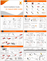
Operating mode
– Inverter with
battery
In order to be able to obtain the highest rate of self-consumption with your PV
system, a battery can be used to store excess energy. The battery is coupled to
the inverter on the direct current side. Multiple current conversion is therefore
not required, and the efficiency is increased.
00 1
6
7
1
Operating mode
– Inverter with
battery and sev-
eral Smart
Meters
00 1
6
7
1
00 1
6
7
2
20
/