Bradford White D-65T-625-3NA User manual

Category
Water heaters & boilers
Type
User manual

This manual is also suitable for

238-41443-00B Rev 7/05
INDUCED DRAFT COMMERCIAL WATER HEATERS
SUPPLEMENT INSTRUCTIONS
TO PART #238-39387-00
THIS INSTRUCTION SUPPLEMENT IS ONLY INTENDED TO GIVE
INSTALLATION INSTRUCTIONS AND INFORMATION RELATED TO THE
INDUCED DRAFT WATER HEATERS WHERE THESE MODELS DIFFER
FROM THE ATMOSPHERICALLY VENTED MODELS IN THE GENERAL
INSTALLATION INSTRUCTIONS (238-39387-00). REFER TO THE
GENERAL INSTRUCTIONS (238-39387-00) FOR ALL APPLICABLE
WARNINGS AND INSTALLATION PROCEDURES.
Specifications and Dimensions
Internet Version for Reference Only
2
Capacity
(gal.)
Input
(BTU/Hr)
AMP
Draw
A
(in.)
B
(in.)
C
(in.)
D
(in.)
Vent
Dia (in.)
65 625,000 3.00 69.38 54.13 41.88 68.88 8.00
80 725,000 3.00 79.63 64.25 55.13 79.13 8.00
Capacity
(Liters)
Input
(kW/Hr)
AMP
Draw
A
(cm)
B
(cm)
C
(cm)
D
(cm)
Vent
Dia
(cm)
246 183.0 3.00 176 137.5 106 175 20.3
303 212.5 3.00 202 163 135 201 20.3
Clearances To Combustible Materials
Sides and Rear Ceiling Vent
6 in. (15.2 cm) 20 in. (51 cm) 6 in. (15.2 cm)
Notes:
1. All models use an induced draft blower with integral damper and
intermittent pilot ignition requiring a power source of (120volt, 60Hz or 220
volt, 50 Hz).
2. Suffix “N” denotes natural gas, Suffix “X” or “P” denotes L.P. gas. Prefix “L”
denotes L.P. on some models.
3. May be installed on combustible flooring.
VENTING
The water heater models described above in this supplement are of the
induced draft type which rely on an induced draft blower to pull the
combustion products through the flue tubes of the water heater. An
integral gravity damper on the induced draft blower outlet is forced open
by the air pressure from the blower and closes at the end of each burner
cycle. NO ADDITIONAL VENT DAMPERS ARE TO BE ATTACHED TO THE
OUTLET OF THESE APPLIANCES.
These water heaters have been approved for vertical venting through a
lined masonry chimney or double wall vent pipe. DO NOT VENT THESE
WATER HEATERS HORIZONTALLY WITH THE VENT TERMINATING
THROUGH THE WALL TO THE OUTSIDE. ALL VENTING MUST
TERMINATE THROUGH THE ROOF WITH A VERTICAL DISCHARGE.
The vent connector attached to the vent collar on the blower must be 8" (20
cm) in diameter. The venting size was designed to produce a negative
pressure inside the venting system when properly installed. Horizontal piping
must be sloped upward at least 1/4" inch per linear foot (2.1 cm/m) of length.
Internet Version for Reference Only
3
All vent piping must be well supported to avoid sagging or adding excessive
weight onto the blower assembly. This water heater may be commonly vented
with another gas appliance, providing the commonly shared vent is the proper
size to handle exhaust gases from both appliances. This water heater must
not have another gas appliance vented into the vent connector. Consult
the venting tables in the latest edition of the National Fuel Gas Code ANSI
Z223.1 or in Canada CAN1-B149.1 or B149.2 and/or local code officials for
proper application for your area. For proper venting, limit the number of elbows
in the venting system. All connections in the venting system must be securely
fastened with sheet metal screws or other approved methods. Consult local
codes and ordinances. Failure to install a proper venting system can result in
fire, injury, or death. See Figures 2 & 3 on the following page for common
venting connections.
Figure 2
Internet Version for Reference Only
4
Figure 3
ELECTRICAL CONNECTIONS
This water heaters must be wired to a (120volt, 60Hz or 220 volt, 50 Hz). power
supply. Refer to the wiring diagram on the water heater and with these
supplemental instructions for proper field wiring connections to the terminal
block. All wiring and conduit must be installed and electrically grounded in
accordance with the latest edition of the National Electric Code (ANSI/NFPA
70) or local applicable codes. In Canada, follow the latest edition of the
Canadian Electrical Code (Part 1, CSA-C22.1) and all applicable local codes.
Refer to the nameplate for the total amp draw for this water heater. The water
heater should be wired on a separate circuit and breaker.
MAINTENANCE OF INDUCED DRAFT BLOWER
The following maintenance should be performed by a qualified service
technician at the minimum periodic interval listed below.
1. Bi-annually, oil the induced draft motor in the ports of the front and rear
motor bearings with 4 drops each of SAE 20 motor oil.
2. Annually, inspect the blower wheel for debris and clean as necessary.
3. Inspect the venting system for corrosion and leaks. Replace any defective
sections of vent pipe.
Internet Version for Reference Only
5
4. Inspect the blower vent damper for proper movement, making sure the
damper extends to the full open position after the blower reaches full speed
(see Figure 5). If the damper blade does not fully open, remove the vent
connector and make sure the blower wheel is clean and debris has not
fallen on the damper blade or blower wheel. If the damper binds, replace
the blower assembly. DO NOT ATTEMPT TO REPAIR THE DAMPER!
Figure 5
REPLACEMENT PARTS LIST FOR INDUCED DRAFT MODELS
Contact your supplier, plumbing professional or the company listed on the
rating plate of the water heater for replacement parts.
Provide the part name as well as the model and serial number(s) of the water
heater(s) when ordering parts. When applicable, the following information shall
be provided: type of gas, voltage and amperage, item number (from the
following list) and description (from the following list).
PART NAME AND DESCRIPTION
1. Induced Draft Blower/Motor Assembly 17. Gas Valve (Emergency Shut-off Device)
2. Blower Mounting Flange 18. Main Burner Orifice(s)
3. Blower Mounting Flange Gasket 19. Control Box
Internet Version for Reference Only
6
4. Collector to Blower Transition Duct 20. Control Box Cover
5. Blower-Vent Pipe Adapter 21. Transformer
6. Air Pressure Switch 22. Ignition Control Module
7. Pressure Switch Tubing 23. Terminal Block
8. Flue Baffle 24. Thermostat
9. Clean-out Hole Tank Cover 25. Capillary Tube Cover
9a. Clean-out Hole Cover O-Ring (not shown) 26. Wire Harness - Thermostat to Blower
9b. Clean-out Hole Cover Gasket (not shown) 27. Wire Harness - Control Box
10. Radiation Shield 28. Wire Harness - Gas Valve
11. Main Burner(s) 29. Flue Collector Cover
12. Burner Tray 30. Flue Collector Cover Gasket
13. Pilot Burner Assembly 31. Anode Rod (Not Shown)
14. Pilot Supply Tube 32. Tank Leg Thermal Break
15. Pilot Draft Shield 33. Manual shut-off (optional)
16. Main Burner Manifold 34. T&P Relief Valve
See the Figure below for parts list drawing
Operating and Troubleshooting Guide - Sequence Of Normal Operation
(White-Rodgers Thermostat With Intermittent Pilot Ignition)
Internet Version for Reference Only
7
1. Thermostat contacts close on temperature drop in the tank causing the
high voltage circuit through the thermostat to be completed to the
transformer and induced draft blower.
2. When the induced draft blower comes up to operating speed, the gravity
damper on the blower outlet is pushed open by the air pressure. The air
pressure in the flue collector chamber is reduced until the vacuum is
sufficient to close the pressure switch contacts (-1.45" w.c. or -.036 kPa).
3. When the pressure switch contacts close, the 24 volt control circuit is
completed to the ("TH" or 24V terminals) ignition control module. The
ignition control module may have a pre-purge time delay of up to 45
seconds. After the pre-purge timing, the ignition control sends 24 volt
power through the thermostat ECO to the pilot valve "PV" terminals on the
gas valve allowing pilot gas to flow to the pilot. The ignition control also
simultaneously sends high voltage, low current electricity through the
electrode wire to the pilot electrode causing sparks to ignite the pilot gas. If
the pilot gas fails to ignite within 90 seconds, the ignition control stops the
pilot gas and sparking. The ignition control may allow the ignition
sequence to "retry" up to 2 more attempts after a 5 minute delay before the
control will "lock out" ignition attempts until the thermostat circuit is reset by
interrupting power for 15 seconds. The induced draft blower continues to
operate as long as the thermostat contacts are closed.
4. When the pilot gas ignites, the flame is sensed by the electrode or a flame
sensing rod. The flame sensing signal received by the ignition control
causes the sparking to stop and the main gas valve to open. The main
burners ignite from the pilot flame. The pilot flame is continually monitored
by the flame sensing circuit. If for any reason, the pilot flame is not sensed
by the electrode or flame sensing rod, the main gas valve closes, the spark
electrode is re-energized, and the ignition trial period is reestablished. The
same sequence occurs during a power or gas supply interruption.
5. The main burners continue to operate until the water temperature in the
tank increases enough to cause the thermostat contacts to open. When
the thermostat contacts open, the 120 volt or 220 volt power is interrupted
to the induced draft blower and the primary transformer windings. The gas
valve closes causing the main and pilot burners to extinguish. The damper
on the blower outlet closes and the pressure switch contacts open.
TROUBLESHOOTING PROCEDURE FOR WHITE-RODGERS
THERMOSTAT
OPERATION: CONDITION: CHECK FOR:
Internet Version for Reference Only
8
Start- Turn
thermostat to
call for heat.
Induced draft blower
starts.
YES NO
- Check to make sure 120 volt or 220 volt power is
present at thermostat terminals to induced draft blower. If
not, make sure power is present at the terminal strip in
the control box. Make sure thermostat contacts close. If
not, replace thermostat.
- If power is present to the blower , but will not operate,
check for continuity from the wires to the blower and the
blower windings. If no continuity check for broken wires.
If wires are O.K. and blower still will not run, replace the
blower.
Pilot ignition
Pilot ignition
(continued)
Pilot ignites after a
30-45 second time
delay (ignition
controls with pre-
purge timings)
YES NO
Does pilot spark after the pre-purge period? If not, check
to make sure pressure switch contacts (mounted on
outside of control box) are closed by checking each
terminal on the pressure switch through the voltmeter with
the other lead to the ground lug. There should be 24 volts
from one terminal to ground. Check the wiring by making
sure 24 volts is available at the "TH" or "24V" terminals on
the ignition control with the other lead of the voltmeter to
the ground lug inside the control box.
- The vacuum at the pressure switch may be checked
with a tee installed at the pressure switch tubing with a
draft gauge or manometer connected. Cold starting
vacuum should be close to -2.0" w.c. (-.49 kPa), with a
hot running operation vacuum near -1.75" w.c. (-.44kPa).
The pressure switch contacts should close by -1.45" w.c.
(-.36kPa) and open in a drop of vacuum to -1.25" w.c. (-
.31kPa). If outside of these specs, replace. DO NOT
LEAVE THE WATER HEATER OPERATING WITH THE
PRESSURE SWITCH BYPASSED.
-Make sure the pressure switch tubing fittings are snug,
but do not use tools to tighten the plastic nut on the
pressure switch connection. Check to make sure the flue
collector lid under the jacket top is tightly secured. The
gasket under the lid must be intact. The gasket under the
blower mounting flange must be secure and the joint
between the blower mounting flange and blower transition
duct must be caulked with high temperature sealant (Dow
RTV or equivalent)
- Make sure the damper position rod is in the open
position while the blower is operating. If the damper
sticks, replace the blower.
- Check the flue baffles to make sure scale or soot
deposits have not accumulated and blocked the flue
passageways.
-Check the amp draw of the induced draft blower if
vacuum to the pressure switch is low. The normal
running amps should be approximately 1.4 amps or 2.8
amps.
-Does pilot spark without lighting pilot? Make sure there
is sufficient gas pressure at the gas valve inlet. Check
the nameplate for minimum gas supply pressures for the
type of gas used.
-Check to make sure 24 volts is present at "PV" wire on
the gas valve. If not, check to make sure ECO high limit
contacts on the two (2) bottom thermostat terminals are
closed (no voltage across terminals, but voltage to
ground). ECO should reset after tank cools. If not, check
for defective control. Also make sure all terminal
connections are tight.
If the pilot valve will not open when voltage is present to
Internet Version for Reference Only
9
the PV terminal and the common terminal "PV/MV" wire
has continuity to the module, the gas valve may be
defective. If no voltage is present at "PV" on the ignition
control, the control may be defective.
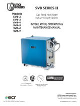
Main burner
ignition
Pilot ignites,
"proves", and main
gas valve opens
with main burners
lighting.
YES NO
- If pilot flame is present, but main burners do not light (no
main burner gas), check to make sure green ground wire
from module to control box ground lug has continuity.
This can be verified by disconnecting the wire and
measuring the resistance through both ends of the wire
with an ohmmeter. The reading should be "0" ohms.
- Check to make sure pilot flame covers the electrode or
flame sensing rod. Check the electrode or flame sensing
wire for continuity. Replace wire if cracked.
- Check for cracked ceramic electrode insulator. Clean
electrode or flame sensing rod if carbon is present.
- Make sure vertical pilot draft shield is installed. Pilot
flame should be steady without wavering or blowing.
- Check for voltage between the "MV" terminal of the
ignition module and the ground lug. If no voltage is
present, and above conditions (ground, pilot flame, flame
sensor, wire leads) are O.K., replace ignition control.
- Check for voltage between MV and MV/PV of the gas
valve. If voltage is present, but valve does not open,
replace gas valve.
Main burners
operate until
thermostat is
satisfied.
Blower and
burners stop.
Main burners
(continued)
Main burners and
blower operate until
thermostat is
satisfied
YES - Checks O.K.
NO
- If blower continues to operate, but main burners cycle
erratically, check for proper grounding of the ignition
control and continuity of the pilot electrode wire. Make
sure the pilot draft shield is in place. The pilot adjustment
screw should be adjusted to the full open position
(counterclockwise). Make sure the pilot electrode is clean
and not damaged or bent. The flame sensing current
output from the pilot can be measured by connecting a
microamp meter from the pilot flame sense lead to the
"sense" terminal on the ignition control. Replace the pilot
if the electrode or wires have deteriorated or if the flame
sense current is below 1.0 microamps. Replace ignition
control if problem persists and above checks proved
satisfactory.
- If the blower continues to operate, but the burners cycle
off, check the ECO (lower) terminals of the thermostat. If
the ECO (high limit) trips, the ignition will "lock out"
requiring resetting. Normally, the thermostat should open
before the high limit trips. If the high limit opens before
the thermostat, replace the control.
- Another possible cause for the burner to cycle is the
pressure switch contacts are opening. Make sure the
pressure switch tubing fittings are snug, but do not use
tools to tighten the plastic nut on the pressure switch
connection. Check to make sure the flue collector lid
under the jacket top is tightly secured. The gasket under
the lid must be intact. The gasket under the blower
mounting flange must be secure and the joint between the
blower mounting flange and blower transition duct must
be caulked with high temperature sealant (Dow RTV or
equivalent). The vacuum at the pressure switch may be
checked with a tee installed at the pressure switch tubing
with a draft gauge or manometer connected. Cold
starting vacuum should be close to -2.0" w.c. (-.49 kPa),
with a hot running operation vacuum near -1.75" w.c. (-.44
kPa). The pressure switch contacts should close by -1.45"
Internet Version for Reference Only
10
w.c. (-.36 kPa) and open in a drop of vacuum to -1.25"
w.c. (-.31 kPa). If outside of these specs, replace. DO
NOT LEAVE THE WATER HEATER OPERATING WITH
THE PRESSURE SWITCH BYPASSED.
Water heater
operates, but
water is not
hot enough.
- Water heater
cycles
- Burners operate
continuously
- Check water heater thermostat setting, adjust if
necessary. Make sure cycling is due to thermostat
setting (check previous sections). Also make sure high
limit contacts are remaining closed by measuring voltage
from each lower thermostat terminal to ground.
- Check outlet water temperature from nearby faucet with
a thermometer. If the outlet water temperature does not
approximate the thermostat setting and the heater is
otherwise functioning normally, the thermostat may be
out of calibration. Remove from tank and replace.
- Make sure there is sufficient gas supply pressure (see
nameplate).
- Check burner manifold pressure (outlet pressure tap on
gas valve)
- Check for proper orifice size for the type of gas used.
- Remove burners and flue baffles and clean as needed.
Make sure gaskets are in good condition (replace if
necessary) before reassembling lid.
- Evaluate hot water usage to determine if hot water draw
exceeds capacity of water heater.
NOTES
Internet Version for Reference Only
11
NOTES
Internet Version for Reference Only
  • Page 1 1
  • Page 2 2
  • Page 3 3
  • Page 4 4
  • Page 5 5
  • Page 6 6
  • Page 7 7
  • Page 8 8
  • Page 9 9
  • Page 10 10
  • Page 11 11

Bradford White D-65T-625-3NA User manual

Category
Water heaters & boilers
Type
User manual
This manual is also suitable for

Ask a question and I''ll find the answer in the document

Finding information in a document is now easier with AI