Compaq Computer Corporation
AlphaServer DS20E
AlphaStation DS20E
Reference Guide
Order Number: ER-K8F6W-UA. D01
This manual is for managers and operators of Compaq
AlphaServer DS20E / AlphaStation DS20E systems.

Revised, August 2000
© 2000 Compaq Computer Corporation.
COMPAQ, the Compaq logo, and AlphaServer Registered in U.S. Patent and Trademark Office.
OpenVMS and Tru64 are trademarks of Compaq Information Technologies Group, L.P.
Linux is a registered trademark of Linus Torvalds in several countries. UNIX is a registered trademark
of The Open Group in the U.S. and other countries.
All other product names mentioned herein may be trademarks of their respective companies.
Compaq shall not be liable for technical or editorial errors or omissions contained herein. The
information in this document is subject to change without notice.

iii
Contents
Preface ........................................................................................................................xi
Chapter 1 System Overview
1.1 System Enclosures ................................................................................ 1-2
1.2 System Parts (Front/Side View)............................................................ 1-4
1.3 System Parts (Rear View) ..................................................................... 1-6
1.4 Operator Control Panel......................................................................... 1-8
1.5 System Board...................................................................................... 1-10
1.6 Server Feature Module ....................................................................... 1-12
1.7 PCI Slots ............................................................................................. 1-14
1.8 Power Supplies.................................................................................... 1-16
1.9 Removable Media Storage................................................................... 1-18
1.10 Hard Disk Drive Storage..................................................................... 1-19
1.11 Two-Way Combination Module........................................................... 1-20
1.12 Console Terminal ................................................................................ 1-21
Chapter 2 Installing the Pedestal System
2.1 System Dimensions and Service Area................................................... 2-2
2.2 Power Requirements............................................................................. 2-3
2.3 Shipment Box........................................................................................ 2-4
2.4 Pedestal Setup ...................................................................................... 2-5
2.5 System Access ....................................................................................... 2-6
2.6 Installing a Pedestal Kit ....................................................................... 2-7
Chapter 3 Installing the Rackmount System
3.1 Rackmount Documentation................................................................... 3-2
3.2 Power Requirements............................................................................. 3-3
3.3 Shipment Box........................................................................................ 3-4
3.4 Marking the Installation Area .............................................................. 3-5
3.5 Rack Accessories ................................................................................... 3-6
3.6 Preparing the System Chassis .............................................................. 3-8
3.7 Preparing the Rack ............................................................................. 3-12

iv
3.8 Installing the System Chassis............................................................. 3-16
3.9 Installing the Interlock System .......................................................... 3-18
3.10 Installing the Cable Management Arm .............................................. 3-20
3.11 Dressing the Cables ............................................................................ 3-22
3.12 Attaching the Front Bezel................................................................... 3-24
Chapter 4 Booting and Installing an Operating System
4.1 Setting Boot Options ............................................................................. 4-2
4.1.1 auto_action...................................................................................... 4-3
4.1.2 bootdef_dev ..................................................................................... 4-5
4.1.3 boot_file........................................................................................... 4-6
4.1.4 boot_osflags..................................................................................... 4-7
4.1.5 ei*0_inet_init or ew*0_inet_init.................................................... 4-11
4.1.6 ei*0_protocols or ew*0_protocols................................................... 4-12
4.2 Booting Tru64 UNIX........................................................................... 4-13
4.2.1 Booting Tru64 UNIX over the Network........................................ 4-16
4.3 Starting a Tru64 UNIX Installation ................................................... 4-18
4.4 Booting Linux...................................................................................... 4-20
4.5 Booting OpenVMS............................................................................... 4-24
4.6 Booting OpenVMS from the InfoServer.............................................. 4-26
4.7 Starting an OpenVMS Installation..................................................... 4-28
Chapter 5 Configuring and Installing Components
5.1 Preparing to Install Components.......................................................... 5-2
5.2 Removing the Side Cover (Pedestal)..................................................... 5-3
5.3 Removing the Top Cover (Rackmount) ................................................. 5-5
5.4 Memory Configuration.......................................................................... 5-6
5.4.1 Installing and Removing DIMMs ................................................... 5-8
5.5 CPU Configuration.............................................................................. 5-10
5.6 Installing a PCI or ISA Option ........................................................... 5-11
5.6.1 Installing a PCI Option................................................................. 5-12
5.6.2 Installing a Multichannel SCSI Option ........................................ 5-14
5.7 Installing a Redundant Power Supply................................................ 5-16
5.8 Network Configuration ....................................................................... 5-18
5.9 Disk Drive Configuration.................................................................... 5-20
5.10 Installing Disk Drives......................................................................... 5-22
5.10.1 Drive Status LEDs........................................................................ 5-24
5.11 Configuring the Storage Subsystem ................................................... 5-26
5.11.1 Connecting a Four-Slot Subsystem............................................... 5-26
5.11.2 Installing a Six-Slot Subsystem.................................................... 5-28

v
5.12 Installing a Tape Drive ....................................................................... 5-35
5.13 External SCSI Expansion ................................................................... 5-37
5.14 AlphaBIOS Configuration Utilities..................................................... 5-38
5.15 Updating Firmware ............................................................................ 5-41
5.15.1 Sources of Firmware Updates....................................................... 5-42
5.15.2 Updating Firmware from the CD-ROM........................................ 5-43
Chapter 6 Remote Management Console
6.1 RMC Overview ...................................................................................... 6-2
6.2 Connecting to RMC............................................................................... 6-3
6.3 Modem Setup ........................................................................................ 6-4
6.4 Dial-In Procedure.................................................................................. 6-5
6.5 Halt Assertion ....................................................................................... 6-7
6.6 RMC Commands ................................................................................... 6-8
6.7 RMC Switch Pack ............................................................................... 6-14
6.7.1 Changing a Switch Setting ........................................................... 6-16
6.7.2 Resetting the RMC to Factory Defaults........................................ 6-17
6.8 Troubleshooting .................................................................................. 6-18
Chapter 7 Using the SRM Console
7.1 SRM Console Overview......................................................................... 7-2
7.1.1 Invoking the SRM Console ............................................................. 7-4
7.2 Command Summary ............................................................................. 7-5
7.3 Getting Help........................................................................................ 7-10
7.4 Displaying the Configuration.............................................................. 7-12
7.5 Displaying the Bootable Devices......................................................... 7-16
7.6 Displaying the Memory Configuration ............................................... 7-18
7.7 Displaying the Power Status............................................................... 7-19
7.8 Displaying the SRM Console Version ................................................. 7-20
7.9 Displaying the CPU Status................................................................. 7-21
7.10 Displaying the PALcode Version......................................................... 7-22
7.11 Booting an Operating System............................................................. 7-23
7.12 Configuring the ISA Bus..................................................................... 7-25
7.13 Testing the System.............................................................................. 7-28
7.14 Starting and Stopping CPUs............................................................... 7-30
7.14.1 halt (or stop).................................................................................. 7-30
7.14.2 continue ........................................................................................ 7-30
7.15 Updating Firmware ............................................................................ 7-32
7.16 Forcing a System Crash Dump ........................................................... 7-36
7.17 Initializing the System........................................................................ 7-37

vi
7.18 Reading a File ..................................................................................... 7-38
7.19 Configuring a PCI NVRAM Module.................................................... 7-40
7.20 Creating a Power-Up Script................................................................ 7-41
7.21 Loading AlphaBIOS ............................................................................ 7-43
7.22 Setting Console Security..................................................................... 7-44
7.22.1 Overview of Secure Mode.............................................................. 7-44
7.22.2 Setting the Console Password....................................................... 7-45
7.22.3 Setting the Console to Secure Mode ............................................. 7-47
7.22.4 Turning Off Security During a Console Session........................... 7-48
7.22.5 Returning to User Mode ............................................................... 7-51
7.23 Setting and Viewing Environment Variables ..................................... 7-52
7.23.1 com*_baud .................................................................................... 7-56
7.23.2 console........................................................................................... 7-57
7.23.3 cpu_enabled .................................................................................. 7-58
7.23.4 ei*0_mode or ew*0_mode.............................................................. 7-60
7.23.5 kbd_hardware_type ...................................................................... 7-61
7.23.6 language........................................................................................ 7-62
7.23.7 os_type .......................................................................................... 7-63
7.23.8 pci_parity ...................................................................................... 7-64
7.23.9 pk*0_fast....................................................................................... 7-65
7.23.10 pk*0_host_id ................................................................................. 7-66
7.23.11 pk*0_soft_term.............................................................................. 7-67
7.23.12 tt_allow_login................................................................................ 7-69
Chapter 8 Troubleshooting
8.1 Error Beep Codes .................................................................................. 8-2
8.2 Diagnostic LEDs on OCP ...................................................................... 8-3
8.3 Power Problems..................................................................................... 8-4
8.4 Console-Reported Failures.................................................................... 8-5
8.5 Boot Problems ....................................................................................... 8-6
8.6 Thermal Problems and Environmental Status..................................... 8-8
8.7 Operating System Reported Failures ................................................... 8-9
8.8 Memory Problems ............................................................................... 8-10
8.9 PCI Bus Problems ............................................................................... 8-11
8.10 SCSI Problems .................................................................................... 8-12
8.11 Fail-Safe Booter Utility....................................................................... 8-13
8.11.1 Starting the FSB........................................................................... 8-13
8.11.2 Preparing Diskettes...................................................................... 8-15
8.11.3 Updating Firmware ...................................................................... 8-16

vii
Chapter 9 Specifications
9.1 Physical Specifications.......................................................................... 9-2
9.2 Environmental Specifications ............................................................... 9-4
9.3 Electrical Specifications........................................................................ 9-5
9.4 Acoustical Data ..................................................................................... 9-7
9.5 Power Cord Requirements .................................................................... 9-8
9.5.1 General Requirements.................................................................... 9-8
9.5.2 Country-Specific Requirements...................................................... 9-9
Appendix A Regulatory and Safety Notices
A.1 Class A and Class B Ratings.................................................................A-1
A.1.1 Class A Device Notices....................................................................A-2
A.1.2 Class B Device Notices....................................................................A-4
A.2 Other Safety Notices.............................................................................A-6
A.2.1 Laser Devices..................................................................................A-6
A.2.2 Battery Replacement ......................................................................A-7
Index

viii
Examples
4–1 Booting Tru64 UNIX from a Local SCSI Disk .................................... 4-13
4–2 RIS Boot .............................................................................................. 4-16
4–3 Text-Based Installation Display ......................................................... 4-18
4–4 Linux Boot Output .............................................................................. 4-21
4–5 Booting OpenVMS from the Local CD-ROM Drive............................. 4-24
4–6 InfoServer Boot ................................................................................... 4-26
4–7 OpenVMS Installation Menu.............................................................. 4-28
7–1 Help (or Man)...................................................................................... 7-10
7–2 Show Config ........................................................................................ 7-12
7–3 Show Device ........................................................................................ 7-16
7–4 Show Memory...................................................................................... 7-18
7–5 Show Power......................................................................................... 7-19
7–6 Show Version ...................................................................................... 7-20
7–7 Show Cpu ............................................................................................ 7-21
7–8 Show Pal.............................................................................................. 7-22
7–9 Tru64 UNIX Boot (Abbreviated)......................................................... 7-23
7–10 Isacfg ................................................................................................... 7-25
7–11 Test...................................................................................................... 7-28
7–12 Halt and Continue............................................................................... 7-30
7–13 Updating Firmware from Floppy ........................................................ 7-32
7–14 Crash ................................................................................................... 7-36
7–15 Init....................................................................................................... 7-37
7–16 More .................................................................................................... 7-38
7–17 Prcache................................................................................................ 7-40
7–18 Editing the Nvram Script ................................................................... 7-41
7–19 Clearing the Nvram Script.................................................................. 7-41
7–20 AlphaBIOS .......................................................................................... 7-43
7–21 Set Password....................................................................................... 7-45
7–22 Set Secure ........................................................................................... 7-47
7–23 Login ................................................................................................... 7-48
7–24 Clear Password ................................................................................... 7-51
7–25 Set envar and Show envar................................................................... 7-52
7–26 User-Created Environment Variable .................................................. 7-52
8–1 Running LFU ...................................................................................... 8-16

ix
Figures
1–1 DS20E System Variants ....................................................................... 1-2
1–2 System Parts......................................................................................... 1-4
1–3 Ports and Connectors............................................................................ 1-6
1–4 Control and Status Indicators............................................................... 1-8
1–5 System Board...................................................................................... 1-10
1–6 Server Feature Module ....................................................................... 1-12
1–7 PCI Slots (Rack Orientation) .............................................................. 1-14
1–8 Power Supplies (Pedestal Orientation)............................................... 1-16
1–9 Removable Media Storage................................................................... 1-18
1–10 Four-Slot and Six-Slot Storage Subsystems ....................................... 1-19
1–11 Combination Module........................................................................... 1-20
1–12 Console Terminal Connections............................................................ 1-21
2–1 System Dimensions............................................................................... 2-2
2–2 Power Supply Requirements................................................................. 2-3
2–3 Unpacking the Shipment ...................................................................... 2-4
2–4 Cabling the System ............................................................................... 2-5
2–5 System Lock and Key............................................................................ 2-6
2–6 Pedestal Kit Contents ........................................................................... 2-8
2–7 Installing the Lower Panel.................................................................. 2-10
2–8 Installing the Upper Panel ................................................................. 2-12
2–9 Installing the Side Dress Panel .......................................................... 2-13
2–10 Installing the Side Access Cover......................................................... 2-14
2–11 Installing the Door .............................................................................. 2-15
3–1 Power Requirements and Connections ................................................. 3-3
3–2 Rackmount System Shipment Box........................................................ 3-4
3–3 Rackmount Installation Area................................................................ 3-5
3–4 Mounting Hardware.............................................................................. 3-6
3–5 Attaching Mounting Brackets to Chassis ............................................. 3-8
3–6 Attaching Slide Brackets to Slides...................................................... 3-10
3–7 Attaching Slide Brackets to Rack Rails .............................................. 3-12
3–8 Stabilizing the Rack ............................................................................ 3-14
3–9 Installing the System into an M-Series Rack ..................................... 3-16
3–10 Installing Shipping Screws ................................................................. 3-17
3–11 Installing the Interlock System .......................................................... 3-18
3–12 Installing the Cable Management Arm .............................................. 3-20
3–13 Dressing the Cables ............................................................................ 3-22
3–14 Attaching the Front Bezel................................................................... 3-24
5–1 Removing the Side Cover ...................................................................... 5-3
5–2 Attaching the Antistatic Wrist Strap.................................................... 5-4

x
5–3 Removing Top Cover ............................................................................. 5-5
5–4 Memory Slot Locations.......................................................................... 5-6
5–5 Installing DIMMs.................................................................................. 5-8
5–6 Removing DIMMs ................................................................................. 5-9
5–7 PCI Slots (Rack Orientation) .............................................................. 5-11
5–8 Installing a PCI Option....................................................................... 5-12
5–9 Multichannel SCSI Installation.......................................................... 5-14
5–10 Adding a Third Supply (Pedestal Orientation) ................................... 5-16
5–11 Network Connection............................................................................ 5-18
5–12 Installing and Removing Disk Drives................................................. 5-22
5–13 Disk Drive LEDs ................................................................................. 5-24
5–14 Subsystem Backplane Connections..................................................... 5-26
5–15 Tape Drive Installation....................................................................... 5-35
5–16 AlphaBIOS Boot Screen...................................................................... 5-38
5–17 AlphaBIOS Setup Menu...................................................................... 5-39
5–18 Run Maintenance Program Dialog Box .............................................. 5-40
5–19 Loadable Firmware Update Utility..................................................... 5-41
6–1 RMC Connections.................................................................................. 6-4
6–2 RMC Switch Pack Defaults................................................................. 6-14
8–1 LED Patterns During Power-Up (Rack Orientation)............................ 8-3
8–2 FSB Switch "On" Setting (Rackmount Orientation).......................... 8-14
Tables
2–1 Pedestal Kit Contents ........................................................................... 2-9
3–1 Mounting Hardware Description .......................................................... 3-7
4–1 OpenVMS Boot Flag Settings ............................................................... 4-9
5–1 Four-Slot SCSI ID Orientation ........................................................... 5-20
5–2 Six-Slot SCSI ID Orientation.............................................................. 5-21
5–3 Drive Status ........................................................................................ 5-25
6–1 RMC Command Summary .................................................................... 6-8
6–2 Status Command Fields...................................................................... 6-13
6–3 RMC Switch Pack Functions............................................................... 6-15
6–4 Troubleshooting RMC ......................................................................... 6-18
7–1 Summary of SRM Console Commands ................................................. 7-5
7–2 Notation Formats for SRM Console Commands................................... 7-7
7–3 Special Characters for SRM Console .................................................... 7-8
7–4 Device Naming Conventions............................................................... 7-16
7–5 PCI Address Assignments................................................................... 7-17
7–6 Environment Variable Summary........................................................ 7-54
8–1 Error Beep Codes .................................................................................. 8-2
8–2 Troubleshooting Power Problems ......................................................... 8-4

xi
8–3 Troubleshooting Console-Reported Failures......................................... 8-5
8–4 Troubleshooting Boot Problems ............................................................ 8-6
8–5 Operating System Reported Failures ................................................... 8-9
8–6 Troubleshooting Memory Problems .................................................... 8-10
9–1 Physical Specifications.......................................................................... 9-2
9–2 Environmental Specifications ............................................................... 9-4
9–3 Electrical Specifications........................................................................ 9-5
9–4 Acoustical Data ..................................................................................... 9-7
9–5 Power Cord Requirements by Country ................................................. 9-9


xiii
Preface
Intended Audience
This manual is for managers and operators of Compaq AlphaServer DS20E /
AlphaStation DS20E systems.
WARNING: To prevent injury, access to internal components is
limited to persons who have appropriate technical training and
experience. Such persons are expected to understand the
hazards of working within this equipment and take measures to
minimize danger to themselves or others. These measures
include:
1. Remove any jewelry that may conduct electricity.
2. Wear an anti-static wrist strap when handling internal
components.
Document Structure
This manual uses a structured documentation design. Topics are organized into
small sections, usually consisting of two facing pages. Most topics begin with an
abstract that provides an overview of the section, followed by an illustration or
example. The facing page contains descriptions, procedures, and syntax
definitions.
This manual has nine chapters and one appendix.
• Chapter 1, System Overview, describes the components of the system.
• Chapter 2, Installing the Pedestal System, gives procedures for setting
up the pedestal system.
• Chapter 3, Installing the Rackmount System, gives procedures for
installing the rack-mountable system into an M-Series cabinet.

xiv
Chapter 4, Booting and Installing an Operating System, explains the
SRM boot environment variables and gives examples of booting Tru64 UNIX,
OpenVMS, and Linux.
Chapter 5, Configuring and Installing Components, shows how to
configure and install components such as memory DIMMs and PCI options.
Chapter 6, Remote Management Console, explains how to use the Remote
Management Console to monitor and control the system.
Chapter 7, Using the SRM Console, describes the SRM commands and
environment variables used to configure the system.
Chapter 8, Troubleshooting, gives basic troubleshooting procedures.
Chapter 9, Specifications, lists the physical, electrical, and environmental
specifications for the system.
Appendix A, Regulatory and Safety Notices, supplies the regulatory
information for Class A and Class B systems as well as safety notices.
Documentation Titles
Table 1 Documentation
Title Order Number
DS20E Reference Guide ER-K8F6W-UA
DS20E Basic Installation ER-K8F6W-IM
DS20E Processor Upgrade ER-PD12U-UG
KN311 CPU Installation Card EK-DSCPU-IN
Memory Option Installation Card EK-MS340-IN
H9A10/H9A15 Rack-Mounting
Template
EK-DS20E-TP
Release Notes EK-K8F6W-RN

xv
Information on the Internet
Visit the following Compaq DS20E Web site for support resources for this
system.
http://www.compaq.com/alphaserver/ds_series.html
Information and files for performing firmware updates is available at:
ftp://ftp.digital.com/pub/Digital/Alpha/firmware/readme.html


System Overview 1-1
Chapter 1
System Overview
This chapter provides an overview of the AlphaServer/AlphaStation DS20E
system, including:
• System enclosures
• System parts (front/side view)
• System parts (rear view)
• Operator control panel
• System board
• Server feature module
• PCI slots
• Power supplies
• Removable media storage
• Hard disk drive storage
• Two-way combination module
• Console terminal

DS20E Reference Guide
1-2
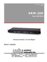
1.1 System Enclosures
The DS20E family consists of a standalone pedestal and a rackmount
system.
Figure 1–1 DS20E System Variants
Rackmount
Pedestal
CAT0039

System Overview 1-3
Enclosure
The system is housed in an enclosure containing the system board, other logic
modules, and two power supplies (maximum of three) with internal fans. The
enclosure has bays for internal mass-storage devices, including a combination
IDE CD-ROM/floppy disk drive, one available half-height removable bay, and
either four 1.6-inch or six
1-inch hot-swap drive bays. An operator control panel includes Power, Reset,
and Halt buttons.
The system can be used as a desk-side pedestal in the vertical position, or with
the addition of brackets, can be mounted in the horizontal position in a
standard rack.
Common Components
The basic building block of the system is the chassis, which houses the following
common components:
• Up to two CPUs, based on the 21264 Alpha chip
• Up to 16, 200-pin memory DIMMs
• Five 64-bit PCI slots and one shared 32-bit ISA or 64-bit PCI slot
• A removable media bay that accommodates one 5-25-inch slim- height
CD/floppy disk combination drive and one 5.25-inch half- height tape device
• One storage disk cage that houses four 1.6-inch drives or a cage that houses
six 1.0-inch drives
• Two 375-watt power supplies and a bay for a third supply for redundancy
• Two serial ports and one parallel port for external options
• An operator control panel with a Power button, Halt button, and Reset
button, and diagnostic LEDs

DS20E Reference Guide
1-4
1.2 System Parts (Front/Side View)
Figure 1–2 identifies the main components of the system in a pedestal
version. Components visible from the front and with the side panel
removed are shown.
Figure 1–2 System Parts
CAT0151b
5
1
6
7
8
10
3
1
4
1
2
4
2
9
Page is loading ...
Page is loading ...
Page is loading ...
Page is loading ...
Page is loading ...
Page is loading ...
Page is loading ...
Page is loading ...
Page is loading ...
Page is loading ...
Page is loading ...
Page is loading ...
Page is loading ...
Page is loading ...
Page is loading ...
Page is loading ...
Page is loading ...
Page is loading ...
Page is loading ...
Page is loading ...
Page is loading ...
Page is loading ...
Page is loading ...
Page is loading ...
Page is loading ...
Page is loading ...
Page is loading ...
Page is loading ...
Page is loading ...
Page is loading ...
Page is loading ...
Page is loading ...
Page is loading ...
Page is loading ...
Page is loading ...
Page is loading ...
Page is loading ...
Page is loading ...
Page is loading ...
Page is loading ...
Page is loading ...
Page is loading ...
Page is loading ...
Page is loading ...
Page is loading ...
Page is loading ...
Page is loading ...
Page is loading ...
Page is loading ...
Page is loading ...
Page is loading ...
Page is loading ...
Page is loading ...
Page is loading ...
Page is loading ...
Page is loading ...
Page is loading ...
Page is loading ...
Page is loading ...
Page is loading ...
Page is loading ...
Page is loading ...
Page is loading ...
Page is loading ...
Page is loading ...
Page is loading ...
Page is loading ...
Page is loading ...
Page is loading ...
Page is loading ...
Page is loading ...
Page is loading ...
Page is loading ...
Page is loading ...
Page is loading ...
Page is loading ...
Page is loading ...
Page is loading ...
Page is loading ...
Page is loading ...
Page is loading ...
Page is loading ...
Page is loading ...
Page is loading ...
Page is loading ...
Page is loading ...
Page is loading ...
Page is loading ...
Page is loading ...
Page is loading ...
Page is loading ...
Page is loading ...
Page is loading ...
Page is loading ...
Page is loading ...
Page is loading ...
Page is loading ...
Page is loading ...
Page is loading ...
Page is loading ...
Page is loading ...
Page is loading ...
Page is loading ...
Page is loading ...
Page is loading ...
Page is loading ...
Page is loading ...
Page is loading ...
Page is loading ...
Page is loading ...
Page is loading ...
Page is loading ...
Page is loading ...
Page is loading ...
Page is loading ...
Page is loading ...
Page is loading ...
Page is loading ...
Page is loading ...
Page is loading ...
Page is loading ...
Page is loading ...
Page is loading ...
Page is loading ...
Page is loading ...
Page is loading ...
Page is loading ...
Page is loading ...
Page is loading ...
Page is loading ...
Page is loading ...
Page is loading ...
Page is loading ...
Page is loading ...
Page is loading ...
Page is loading ...
Page is loading ...
Page is loading ...
Page is loading ...
Page is loading ...
Page is loading ...
Page is loading ...
Page is loading ...
Page is loading ...
Page is loading ...
Page is loading ...
Page is loading ...
Page is loading ...
Page is loading ...
Page is loading ...
Page is loading ...
Page is loading ...
Page is loading ...
Page is loading ...
Page is loading ...
Page is loading ...
Page is loading ...
Page is loading ...
Page is loading ...
Page is loading ...
Page is loading ...
Page is loading ...
Page is loading ...
Page is loading ...
Page is loading ...
Page is loading ...
Page is loading ...
Page is loading ...
Page is loading ...
Page is loading ...
Page is loading ...
Page is loading ...
Page is loading ...
Page is loading ...
Page is loading ...
Page is loading ...
Page is loading ...
Page is loading ...
Page is loading ...
Page is loading ...
Page is loading ...
Page is loading ...
Page is loading ...
Page is loading ...
Page is loading ...
Page is loading ...
Page is loading ...
Page is loading ...
Page is loading ...
Page is loading ...
Page is loading ...
Page is loading ...
Page is loading ...
Page is loading ...
Page is loading ...
Page is loading ...
Page is loading ...
Page is loading ...
Page is loading ...
Page is loading ...
Page is loading ...
Page is loading ...
Page is loading ...
Page is loading ...
Page is loading ...
Page is loading ...
Page is loading ...
Page is loading ...
Page is loading ...
Page is loading ...
Page is loading ...
Page is loading ...
Page is loading ...
Page is loading ...
Page is loading ...
Page is loading ...
Page is loading ...
Page is loading ...
Page is loading ...
Page is loading ...
Page is loading ...
Page is loading ...
Page is loading ...
Page is loading ...
Page is loading ...
Page is loading ...
Page is loading ...
Page is loading ...
Page is loading ...
Page is loading ...
Page is loading ...
Page is loading ...
Page is loading ...
Page is loading ...
Page is loading ...
Page is loading ...
Page is loading ...
Page is loading ...
Page is loading ...
Page is loading ...
Page is loading ...
Page is loading ...
Page is loading ...
Page is loading ...
Page is loading ...
Page is loading ...
Page is loading ...
Page is loading ...
Page is loading ...
Page is loading ...
Page is loading ...
Page is loading ...
Page is loading ...
Page is loading ...
Page is loading ...
Page is loading ...
Page is loading ...
Page is loading ...
Page is loading ...
Page is loading ...
/