Page is loading ...

SPKE SERIES
UL 1971 COMPLIANT
SPEAKER AND SPEAKER/STROBE
Installation Instructions-
Owner's Information
MODELS
SPKE4*.................. SQUARE SPEAKER
SPKE4*.................. SQUARE SPEAKER WITH 24 VDC STROBE
SPKE8*.................. 8 IN. ROUND SPEAKER
SPKE8*.................. 8 IN. ROUND SPEAKER WITH 24 VDC STROBE
* Includes any of the following suffixes, number indicating candela rating, R (Red) or
W (Off-White), W (Wall) or C (Ceiling).
I. INTRODUCTION
The Gentex SPKE Series is a high quality speaker and speaker/visual signal appliance. The
SPKE Series is UL Listed for fire protective service. The high intensity strobe utilizes a Xenon
flash tube which generates a high-intensity light visible from all sides. The strobe is UL Listed in
compliance with UL 1971, Signaling Appliances for the Hearing Impaired (15/75 Cd and 30/75 Cd
models are additionally listed in compliance with UL 1638).
II. PRODUCT INFORMATION
The SPKE Series speaker and speaker/strobe offer a choice of field selectable power taps, 1/8,
1/4, 1/2, 1, 2 and 4 Watts for either 25v or 70.7v audio amplifiers. The speaker/strobe offers the
option of a high intensity strobe which complies with UL 1971. The frequency range of the
speakers is 400-4000Hz. All devices are suitable for line supervision. Speaker includes DC
blocking capacitor which allows for supervision voltage of either polarity.
III. LOCATION
This appliance is intended for use in Fire Alarm Systems and is to be installed in accordance with
this installation manual, the recommendation of the local authorities having jurisdiction, and other
NFPA Standards that provide standards on notification appliances for protective signaling
systems.
The Gentex "SPKE" is intended for indoor installation only. This appliance is not weatherproofed
for outdoor or drip proof applications.
Wall-mounted appliances shall have their bottoms at heights above the finished floor of not less
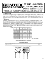
than 80 in. (2m) and no greater than 96 in. (2.4m)**. Spacing shall be in accordance with Table A.
If a room configuration is not square, the room size that will entirely encompass the room or
subdivide the room into multiple squares shall be used.
Maximum Room Minimum Required Light Output, Candela (Cd)
Size (Effective Intensity)
Two Lights per Four Lights
Room (Located per Room
One Light on Opposite (One Light
per Room (Cd) Walls) (Cd) per Wall) (Cd)
20' x 20' 15 N/A N/A
30' x 30' 30 15 N/A
40' x 40' 60 30 15*
50' x 50' 95 60 30*
60' x 60' 135 95 30*
70' x 70' 185 95 60*
80' x 80' 240 135 60
90' x 90' 305 185 95
100' x 100' 375 240 95
110' x 110' 455 240 135
120' x 120' 540 305 135
130' x 130' 635 375 185
TABLE A * - Must be used with the AVS44 Control Module due to distance between strobes being less than 55ft.
VII. ELECTRICAL SPECIFICATIONS:
MODEL NUMBERS SPEAKERS dBA @ 10 FEET
PER UL 1480
RATED WATTS 1/8 1/4 1/2 1 2 4
SPKE4 SERIES 78 81 84 87 90 90
SPKE8 SERIES 78 81 84 87 90 90
STROBE CURRENT RATINGS
DC (mA) FWR (mA)
Cd VOLTAGE INRUSH PEAK AVG INRUSH PEAK AVG
21V 96 94 86 132 236 110
15 24V 114 84 78 176 216 100
30V 150 76 69 176 200 91
21V 110 120 105 245 280 140
15*& 30 (wall) 24V 130 110 93 235 260 125
30V 160 90 77 310 245 115
21V 120 150 130 320 360 180
15*(ceiling) & 60 (wall) 24V 140 120 115 300 340 160
30V 170 100 95 400 330 145
21V 110 180 165 180 480 224
30*(wall) & (ceiling) 24V 120 160 142 180 440 193
30V 160 140 114 220 400 165
21V 128 270 240 220 752 310
110 24V 148 240 220 280 704 298
30V 230 200 179 420 552 234
SYNCHRONIZED STROBE RATINGS
21V 420 180 98 440 260 115
15 (Z suffix) 24V 490 160 92 600 350 107
30V 620 160 85 640 380 100
21V 420 440 144 550 920 172
15* (Z suffix) 24V 490 680 130 640 920 155
30V 620 580 116 700 640 138
*-RATED 75 Cd PER UL 1638, FIRE PROTECTIVE VISUAL SIGNALING APPLIANCES.
LIMITED WARRANTY
For a period of 24 months from the date of purchase, or a
maximum of 30 months from the date of manufacture, Gentex
warrants to you, the original purchaser, that your appliance will be free
from defects in workmanship, materials, and construction under
normal use and service. If a defect in workmanship, materials, or
construction should cause your appliance to become inoperable within
the warranty period, Gentex will repair your appliance or furnish you
with a new or rebuilt replacement appliance without charge to you
except for postage required to return the appliance to us. Gentex will
not reimburse you for repairs or replacement parts provided by other
parties. Your repaired or replacement appliance will be returned to you
free of charge and it will be covered under this warranty for the balance
of the warranty period.
This warranty is void if our inspection of your appliance shows that
the damage or failure was caused by abuse, misuse, abnormal usage,
faulty installation, improper maintenance, or repairs other than those
performed by us.
ANY WARRANTIES IMPLIED UNDER ANY STATE LAW,
INCLUDING IMPLIED WARRANTIES OF MERCHANTABILITY OR
FITNESS FOR A PARTICULAR PURPOSE, APPLY ONLY FOR THE
WARRANTY PERIOD SPECIFIED ABOVE. PLEASE NOTE THAT
SOME STATES DO NOT ALLOW LIMITATIONS ON HOW LONG AN
IMPLIED WARRANTY LASTS, SO THE ABOVE EXCLUSION MAY
NOT APPLY TO YOU.
GENTEX WILL NOT BE LIABLE FOR ANY LOSS, DAMAGE,
INCIDENTAL OR CONSEQUENTIAL DAMAGES OF ANY KIND
ARISING IN CONNECTION WITH THE SALE, USE OR REPAIR OF
THIS APPLIANCE. THE MAXIMUM LIABILITY OF GENTEX SHALL
NOT IN ANY CASE EXCEED THE PURCHASE PRICE PAID BY
YOU FOR THE APPLIANCE. PLEASE NOTE THAT SOME STATES
DO NOT ALLOW THE EXCLUSION OR LIMITATION OF
INCIDENTAL OR CONSEQUENTIAL DAMAGES, SO THE ABOVE
EXCLUSION MAY NOT APPLY TO YOU.
If a defect in workmanship, materials, or construction should
cause your appliance to become inoperable within the warranty
period, you must return the appliance to Gentex postage prepaid.
You must also prove to the satisfaction of Gentex the date of
purchase of your appliance. Warranty service may only be
performed by Gentex personnel at Gentex's facilities in Zeeland,
Michigan. You must also pack the appliance to minimize the risk of it
being damaged in transit. You must also enclose a return address.
Appliances returned for warranty service should be sent to: Gentex
Corporation, 10985 Chicago Drive, Zeeland, MI 49464. If we
receive an appliance in a damaged condition as the result of
shipping, we will notify you and you must file a claim with the shipper.
THIS WARRANTY GIVES YOU SPECIFIC LEGAL RIGHTS AND
YOU MAY ALSO HAVE OTHER RIGHTS WHICH VARY FROM
STATE TO STATE.
GENTEX CORPORATION
10985 CHICAGO DRIVE, ZEELAND, MI 49464
PHONE: 800-436-8391
550-105-11
1-1-94
RATED WATTS 1/8 1/4 1/2 1 2 4
INPUT 25v RMS D E F G H I
INPUT 70.7v RMS A B C D E F
WIRING DIAGRAM

**Effective Intensity Requirements for Sleeping Area
Visible Notification Appliance
Distance from Ceiling to Top of Lens Intensity
greater than or equal to 24" 110 Cd
less than 24" 177 Cd
IV. MOUNTING ROUGH-IN BOX AND RUN WIRING
MOUNTING OPTIONS
All models shown with optional strobe.
SYSTEM CONSIDERATIONS
1. To select the proper wattage input for the speaker. Move the jumper to the appropriate pin.
Refer to Section VII for the proper terminal.
2. Always maintain electrical isolation between speaker and strobe wiring on combination units.
3. Do not exceed 130% of rated speaker voltage. If excessive distortion is heard, check
amplifier for signal clipping. If clipping exists, reduce either amplifier input or gain.
4. When extension rings are used, the conduit should always enter through the backbox.
CAUTION
WHEN INSTALLING, ROUTE FIELD WIRING AWAY FROM SHARP
PROJECTIONS, CORNERS AND INTERNAL COMPONENTS.
NOTE: Strobes are not recommended for use on coded or pulsing signaling circuits.
PANEL VOLTAGE - DEVICE MINIMUM VOLTAGE
TOTAL CURRENT DRAW
* INCLUDES WIRE TO AND FROM APPLIANCE.
ASSUMES ALL APPLIANCES ARE AT THE END OF WIRE RUN (WORST CASE).
CAUTION: APPLIES ONLY TO REGULATED SUPPLIES.
V. CHECKOUT AND TROUBLESHOOTING
1. Supply power to the system control panel. The auxiliary signaling device should not be
activated.
2. If the signal is activated:
a. Check all smoke and fire detectors in the system to make sure they have not been
activated.
b. Check all wiring connections to make sure the signal detection circuits are not reversed or
shorted together. Check wire color codes and traces.
3. To test the "SPKE" series and other signaling appliances, trip the auxiliary panel or activate
alarm circuit at the main control panel or activate one of the fire detection units in the system.
All auxiliary signals should be activated.
4. An operational test on this product should be conducted in accordance with National Standards
or at a minimum annually and more often if dictated by local and state codes or authorities
having jurisdiction.
SIGNALING APPLIANCE LIMITATIONS:
Your speaker meets or exceeds current audibility requirements of Underwriters Laboratories.
However, if the appliance is located outside a bedroom it may not wake up a sound sleeper,
especially if the room door is closed or only partially open.
WARNING
THIS APPLIANCE WILL NOT OPERATE WITHOUT ELECTRICAL POWER. AS
FIRES FREQUENTLY CAUSE POWER INTERRUPTIONS, GENTEX SUGGESTS
YOU DISCUSS FURTHER SAFEGUARDS WITH YOUR LOCAL FIRE
PROTECTION SPECIALIST.
VI. TO RETURN A UNIT
Should you experience problems with your "SPKE" unit, proceed as follows:
1. Turn off electrical power to the auxiliary alarm circuit.
2. Unscrew the unit from the mounting box.
3. Disconnect the unit from the field wiring. Reconnect the two positive supply voltage circuits
(red wires) and the two negative supply voltage circuits (black wires) of the auxiliary alarm
circuit to maintain power to the other auxiliary alarm appliances in the system.
4. Carefully pack the defective unit (the manufacturer cannot be responsible for consequential
damage due to shipping or mishandling). Include your return address and complete details as
to the nature of the difficulties being experienced and date of installation.
5. Return to: Gentex Corporation, 10985 Chicago Drive, Zeeland, MI 49464. Prior to returning,
call Gentex @ 1-800-436-8391 to obtain an RMA number from our return department.
NOTE: DO NOT USE
LOOPED WIRE UNDER
TERMINALS. BREAK WIRE
RUN TO PROVIDE
SUPERVISION OF
CONNECTION.
*MAX. WIRE DISTANCE (IN FEET) = X WIRE CONDUCTIVITY (STROBE ONLY)
/