GEC24, GES24, GEH24 GEC3-24 & GES3-24 SERIES
ANSI/UL & CAN/ULC COMPLIANT
GECA24, GESA24, GECB24, GESB24, GECG24,
GESG24, GECR24 & GESR24, WGEC24, WGES24
WGECA24, WGESA24, WGECB24, WGESB24,
WGECG24, WGESG24, WGECR24 & WGESR24 SERIES
ANSI/UL & CAN/ULC COMPLIANT
VISIBLE AND/OR AUDIBLE
SIGNALING APPLIANCES
I. INTRODUCTION
The Gentex models GEC24, GES24, GEH24, GEC3-24, GES3-24, WGEC24, WGES24, GECA24, GESA24, GECB24, GESB24, GECG24, GESG24, GECR24, GESR24, WGECA24,
WGESA24, WGECB24, WGESB24, WGECG24, WGESG24, WGECR24, WGESR24 are high quality audible and/or visible signaling appliances. The high intensity strobe utilizes a Xenon flash
tube that generates a high-intensity flash visible from all angles. This appliance is intended to provide a visible, audible or audible/visible, depending on the model, notification signal for the
purpose of life safety and property protection. The GEC3-24, GES3-24, GECA24, GESA24, GECB24, GESB24, GECG24, GESG24, GECR24, GESR24 are provided with a slider switch which
allows for candela selection at the installation site; the candela intensities which can be selected are 15Cd, 30Cd, 60Cd, 75Cd, or 110Cd (24VDC only). The GEC24 and GES24 are fixed
candela units; the candela intensities which can be ordered, are 177Cd and 15/75Cd. The WGEC24, WGES24, WGECA24, WGESA24, WGECB24, WGESB24, WGECG24, WGESG24,
WGECR24, WGESR24 are fixed candela units, available in a 75 candela intensity only. This appliance is ideal for any occupancy that requires notification appliances per the applicable building
or fire code or wherever dependable alarms are required.
The GEC24, GES24, GEC3-24, GES3-24 strobe is listed in compliance with ANSI/UL 1971, Signaling Appliances for the Hearing Impaired (the 15/75Cd model on the GEC24 and GES24 is
additionally listed in compliance with ANSI/UL 1638). The WGEC24, WGES24, GECA24, GESA24, GECB24, GESB24, GECG24, GESG24, GECR24, GESR24, WGECA24, WGESA24,
WGECB24, WGESB24, WGECG24, WGESG24, WGECR24, WGESR24 strobe is listed in compliance with ANSI/UL 1638, Visual Signaling Appliances - Private Mode Emergency and General
Signaling. Additionally, colored lens models GECA24, GESA24, GECB24, GESB24, GECG24, GESG24, GECR24, GESR24 comply with the polar dispersion requirements of ANSI/UL 1971.
II. LOCATION
This appliance is intended for use in fire alarm systems and is to be installed in accordance with this manual, the recommendation of the local authorities having jurisdiction, and other NFPA
documents that provide standards on notification appliances for protective signaling systems. The GEC24, GES24, GEH24, GEC3-24, GES3-24, GECA24, GESA24, GECB24, GESB24,
GECG24, GESG24, GECR24, GESR24 are intended for indoor installations only; this appliance is not listed for outdoor or drip proof applications. The WGEC24, WGES24, WGECA24,
WGESA24, WGECB24, WGESB24, WGECG24, WGESG24, WGECR24, WGESR24 are intended for indoor or outdoor installations; this appliance is rated for outdoor or drip proof applications
when used in conjunction with the GOE or GOELP Enclosure.
Wall mounted strobe and horn/strobe appliances shall have their entire lens at heights above the finished floor of not less than 80 in. (2m) and not greater than 96 in. (2.4m)**. Spacing shall be
in accordance with Table A. If a room configuration is not square, the room size that will entirely encompass the room or subdivide the room into multiple squares shall be used. Wall mounted
horn only appliances shall have their tops above the finished floors at heights of not less than 90 in. (2.30m) and below the finished ceilings at heights of not less than 6 in. (152mm). Different
mounting heights shall be permitted by the AHJ provided the sound pressure level requirements of NFPA 72 are met.
III. MOUNTING, ROUGH-IN BOX AND RUN WIRING
This unit is designed for mounting to most single gang boxes, 4" square outlet boxes, 2-gang masonry boxes or non-metallic 2-gang switch boxes. Conduit entrance to boxes should be
selected to insure sufficient wiring clearance.
1. Run a minimum 18 gauge insulated 2 or more conductor cable.
2. Mount a box for each remote signaling appliance. Screw bracket onto box. Insert signal into bracket and slide to the right firmly into the terminal block receptacle. Place housing over
mounted assembly and screw together with single screw at the bottom of the signal. Cover screw with plastic tab.
NOTICE: WIRING SHOULD BE CONNECTED TO MOUNTING BRACKET PRIOR TO MOUNTING SIGNAL. INCOMING POSITIVE POWER LEAD MUST BE BROKEN AND EACH LEAD IS
TO BE INSERTED INTO EACH OF THE TOP TWO TERMINALS. IF TWO POWER RUNS ARE MADE TO THE SIGNAL, ONE FOR THE STROBE AND ONE FOR THE HORN, ONLY ONE OF
THE RUNS MUST HAVE ITS POSITIVE LEAD BROKEN AND PLACED UNDER THE TWO SEPARATE TOP TERMINALS. A BARRIER IS PROVIDED TO PREVENT BOTH LEADS FROM
BEING PLACED UNDER THE SAME TERMINAL.
NA = Not allowable
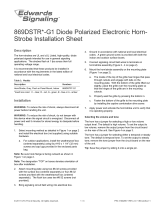
Table A
Room Spacing for Wall-Mounted Visible Appliances per NFPA 72, 2013 Edition
Maximum Room Size Minimum Required Light Output ( Effective Intensity, Cd)
Meters Feet
One Light
per Room
Four Lights per Room
(One Light per Wall)
6.10 x 6.10 20 x 20 15 NA
8.53 x 8.53 28 x 28 30 NA
9.14 x 9.14 30 x 30 34 NA
12.2 x 12.2 40 x 40 60 15
13.7 x 13.7 45 x 45 75 19
15.2 x 15.2 50 x 50 94 30
16.5 x 16.5 54 x 54 110 30
16.8 x 16.8 55 x 55 115 30
18.3 x 18.3 60 x 60 135 30
19.2 x 19.2 63 x 63 150 37
20.7 x 20.7 68 x 68 177 43
21.3 x 21.3 70 x 70 184 60
24.4 x 24.4 80 x 80 240 60
27.4 x 27.4 90 x 90 304 95
30.5 x 30.5 100 x 100 375 95
33.5 x 33.5 110 x 110 455 135
36.6 x 36.6 120 x 120 540 135
39.6 x 39.6 130 x 130 635 185
550-0011
Page 1
GEC24, GES24, GEC3-24, GES3-24 PRODUCT INFORMATION
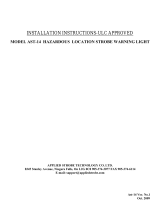
**Effective Intensity Requirements for Sleeping Areas
Visible Notification Appliance
Distance from Ceiling to Top of Lens Intensity
greater than or equal to 24" 110cd
less than 24" 177cd
CAUTION:
Strobe light must be
installed within 16 feet
of the pillow when
used in a sleeping
area.
ADDITIONAL CAN/ULC LISTED PRODUCT INFORMATION IS FOUND ON PAGES 5 AND 6