Page is loading ...

ICE-O-Matic
11100 East 45th Ave
Denver, Colorado 80239
Part Number 9081350-01 Date 2/07
SERVICE AND INSTALLATION MANUAL
GEM0650A/W,GEM0956A/W and GEM1256A/W
GEM0655 Air


GEM0650/0956/1256 A/W Forward
Page i
How To Use This Manual
ICE-O-Matic provides this manual as an aid to the end user and service technician in installation and
maintenance of the GEM Series ice machines. Do not attempt to perform installation, start-up or maintenance
unless you have read and fully understand this manual.
If, at any time, you encounter conditions that are not addressed in this manual, call, E-mail or write the ICE-O-
Matic Service Department:
ICE-O-Matic
11100 E. 45
th
Ave.
Denver, Co. 80239
Attn: Technical Service Department
E-Mail: [email protected]
Telephone Numbers Any Service communication must include:
800-423-3367 All Departments • Model Number
888-349-4423 Technical Assistance Only • Serial number
303-371-3737 • A detailed explanation of the problem
Keep this manual for future reference.
The GEM0650A/W, GEM0956A/W and GEM1256A/W Series Service Parts Manuals are available separately.
ICE-O-Matic icemakers and dispensers are not approved for outdoor installation.
WARNING: Always disconnect electrical power and shut off water supply whenever maintenance or
repairs are performed on the ice machine and related equipment.
CAUTION: Always wear protective eyewear whenever maintenance or repairs are performed on the ice
machine and related equipment

GEM0650/0956/1256 A/W Table Of Contents
Page ii
Table of Contents
Forward........................................................................................................................................ Page i
Table Of Contents........................................................................................................................ Page ii
Freight Claim Procedure.............................................................................................................. Page iii
Warranty...................................................................................................................................... Page iv
For The Installer (Guidelines)...................................................................................................... Page 1
For The Installer (Applications).................................................................................................... Page 4
For The Installer (Location).......................................................................................................... Page 6
For The Plumber.......................................................................................................................... Page 7
For The Electrician....................................................................................................................... Page 8
For The Installer (Check List) ...................................................................................................... Page 9
Start Up........................................................................................................................................ Page 10
Component Description............................................................................................................... Page 11
Electrical Sequence..................................................................................................................... Page 14
Operation: Water ......................................................................................................................... Page 15
Operation: Performance .............................................................................................................. Page 16
Sanitizing and Cleaning............................................................................................................... Page 17
Bearing Maintenance................................................................................................................... Page 18
Sensor Maintenance.................................................................................................................... Page 19
Air Cooled Maintenance .............................................................................................................. Page 20
Auger Maintenance...................................................................................................................... Page 21
Service Diagnosis........................................................................................................................ Page 22
Control System Diagnostics......................................................................................................... Page 24
Removal and Replacement: Water Reservoir and Bin Controls.................................................. Page 25
Removal and Replacement: Bearing and Breaker ...................................................................... Page 26
Removal and Replacement: Auger.............................................................................................. Page 27
Removal and Replacement: Water Seal...................................................................................... Page 28
Removal and Replacement: Evaporator...................................................................................... Page 29
Removal and Replacement: Gear Motor..................................................................................... Page 30
Removal and Replacement: Fan Blade and Fan Motor............................................................... Page 31
Refrigeration System Service...................................................................................................... Page 32
Wiring Diagram: GEM0650.......................................................................................................... Page 33
Wiring Diagram: GEM0956.......................................................................................................... Page 34
Wiring Diagram: GEM1256.......................................................................................................... Page 35
Wiring Diagram: GEM0655.......................................................................................................... Page 36
Service History............................................................................................................................. Page 37

GEM0650/0956/1256 A/W Freight Claim Procedure
Page iii
Important!
Inspect Promptly
This merchandise has been carefully inspected and packed in accordance with the carrier’s packing
specifications. Responsibility for safe delivery has been assumed by the carrier. If loss or damage occurs, you
as the consignee must file a claim with the carrier and hold the container for carrier’s inspection.
Visible Loss or Damage
Any external evidence of loss or damage must be fully described and noted on your freight bill or express
receipt and signed by the carrier’s agent. Claim should be filed on a form available from the carrier.
Concealed Loss or Damage
If loss or damage does not appear until merchandise has been unpacked, make a written request for
inspection by the carrier within 15 days of the delivery date. Then file a claim on a form from the carrier.
File Claim Without Delay Do Not Return Damaged Merchandise to ICE-O-Matic

GEM0650/0956/1256 A/W Warranty
Page iv
ICE-O-Matic
Parts and Labor
Domestic & International Limited Warranty
Mile High Equipment LLC (the “Company”) warrants ICE-O-Matic brand ice machines, ice dispensers, remote condensers, water filters, and ice storage
bins to the end customer against defects in material and factory workmanship for the following:
• Cube ice machines, compressed ice machines and remote
condensers. - Thirty-six (36) months parts and labor
• Ice storage bins -Twenty-four (24) month parts and labor
• Flake ice machines - Twenty-four (24) months parts and
labor
• IOD model dispensers - Twenty-four (24) months parts, Twelve (12) months
labor
• CD model dispensers - Thirty-six (36) months parts and
labor
• Water filter systems - Twelve (12) months parts and labor (not including filter
cartridges)
An additional twenty-four (24) month warranty on parts (excluding labor) will be extended to all cube ice machine evaporator plates and all cube ice and
compressed ice machine compressors from the date of original installation. An additional thirty-six (36) month warranty on parts (excluding labor) will be
extended to all flake ice machine compressors from the date of original installation The company will replace EXW (Incoterms 2000) the Company plant
or, EXW (Incoterms 2000) the Company-authorized distributor, without cost to the Customer, that part of any such machine that becomes defective. In
the event that the Warranty Registration Card indicating the installation date has not been returned to ICE-O-Matic, the warranty period will begin on the
date of shipment from the Company. Irrespective of the actual installation date, the product will be warranted for a maximum of seventy-two (72) months
from date of shipment from the Company.
ICE-model cube ice machines which are registered in the Water Filter Extended Warranty Program will receive a total of eighty-four (84) months parts
and labor coverage on the evaporator plate from the date of original installation. Water filters must be installed at the time of installation and registered
with the Company at that time. Water filter cartridges must be changed every six (6) months and that change reported to the Company to maintain the
extended evaporator warranty.
No replacement will be made for any part or assembly which (I) has been subject to an alteration or accident; (II) was used in any way which, in the
Company’s opinion, adversely affects the machine’s performance; (III) is from a machine on which the serial number has been altered or removed; or,
(IV) uses any replacement part not authorized by the Company. This warranty does not apply to destruction or damage caused by unauthorized service,
using other than ICE-O-Matic authorized replacements, risks of transportation, damage resulting from adverse environmental or water conditions,
accidents, misuse, abuse, improper drainage, interruption in the electrical or water supply, charges related to the replacement of non-defective parts or
components, damage by fire, flood, or acts of God.
This warranty is valid only when installation, service, and preventive maintenance are performed by a Company-authorized distributor, a Company-
authorized service agency, or a Company Regional Manager. The Company reserves the right to refuse claims made for ice machines or bins used in
more than one location This Limited Warranty does not cover ice bills, normal maintenance, after-install adjustments, and cleaning.
Limitation of Warranty
This warranty is valid only for products produced and shipped from the Company after January, 2007. A product produced or installed before that date
shall be covered by the Limited Warranty in effect at the date of its shipment. The liability of the Company for breach of this warranty shall, in any case,
be limited to the cost of a new part to replace any part, which proves to be defective. The Company makes no representations or warranties of any
character as to accessories or auxiliary equipment not manufactured by the Company. REPAIR OR REPLACEMENT AS PROVIDED UNDER THIS
WARRANTY IS THE EXCLUSIVE REMEDY OF THE CUSTOMER. MILE HIGH EQUIPMENT SHALL NOT BE LIABLE FOR ANY INCIDENTAL OR
CONSEQUENTIAL DAMAGES FOR BREACH OF ANY EXPRESS OR IMPLIED WARRANTY ON THIS PRODUCT. EXCEPT TO THE EXTENT
PROHIBITED BY APPLICABLE LAW, ANY IMPLIED WARRANTY OR MERCHANTABILITY OR FITNESS FOR A PARTICULAR PURPOSE ON THIS
PRODUCT IS LIMITED IN DURATION TO THE LENGTH OF THIS WARRANTY.
Filing a Claim
All claims for reimbursement
must be received at the factory within 90 days from date of service to be eligible for credit. All claims outside this
time period will be void. The model, the serial number and, if necessary, proof of installation, must be included in the claim. Claims for labor to
replace defective parts must be included with the part claim to receive consideration. Payment on claims for labor will be limited to the published labor
time allowance hours in effect at the time of repair. The Company may elect to require the return of components to validate a claim. Any defective part
returned must be shipped to the Company or the Company-authorized distributor, transportation charges pre-paid, and properly sealed and tagged. The
Company does not assume any responsibility for any expenses incurred in the field incidental to the repair of equipment covered by this warranty. The
decision of the Company with respect to repair or replacement of a part shall be final. No person is authorized to give any other warranties or to assume
any other liability on the Company’s behalf unless done in writing by an officer of the Company.
GOVERNING LAW
This Limited Warranty shall be governed by the laws of the state of Delaware, U.S.A., excluding their conflicts of law principles. The United Nations
Convention on Contracts for the International Sale of Goods is hereby excluded in its entirety from application to this Limited Warranty.
Mile High Equipment LLC, 11100 East 45
th
Avenue, Denver, Colorado 80239 (303) 371-3737
January 2007

GEM0650/0956/1256 A/W For the Installer
Page 1
Installation Guidelines:
For proper operation of the ICE-O-Matic ice machine, the following installation guidelines must be followed.
Failure to do so may result in loss of production capacity, premature part failures, and may void all warranties.
Ambient Operating Temperatures:
Minimum Operating Temperature: 50°F (10°C)
Maximum Operating Temperature 100°F (38°C)
Note: ICE-O-Matic ice makers and dispensers are not approved for outdoor installation.
Incoming Water Supply
Minimum incoming water temperature: 40°F (4.5°C)
Maximum incoming water temperature: 100°F (38°C)
Minimum incoming water pressure: 20 psi (1.4 bar)
Maximum incoming water pressure: 80 psi (4.1 bar)
Note: If water pressure exceeds 80 psi a water pressure regulator must be installed.
Drains
All drain lines must be installed per local codes. Flexible tubing is not recommended. Route bin drain, vented
float overflow drain and water condenser drain individually to a floor drain. The use of condensate pumps for
draining water is not recommended by ICE-O-Matic. ICE-O-Matic assumes no responsibility for improperly
installed equipment.
Water Filtration
A water filter system should be installed with the ice machine.
Clearance Requirements
Self-contained air cooled ice machines must have a minimum of 6 inches (15cm) of clearance at the sides of
the ice machine for proper air circulation.
Stacking
ICE-O-Matic GEM ice machines are not designed to be stacked.
Dispenser Application
The GEM ice machine is approved for specific dispenser applications, reference page 4.
Electrical Specifications
Refer to the serial plate at the rear of the ice machine to make sure proper voltage and circuit breaker size
have been supplied. Make sure the machine is on a dedicated circuit. The GEM Series are not supplied with
an electrical power cord and will need to be installed and wired per local electrical codes.
Adjustments
Level the machine within 1/8 inch in all directions. Adjust the cabinet or bin legs as required.
Check the bin control for proper operation.
Check the water level in the reservoir for proper adjustment.
Check the water regulating valve adjustment if water cooled.

GEM0650/0956/1256 A/W For The Installer
Page 2
GEM0650/0655/0956A/W

GEM0650/0956/1256 A/W For The Installer
Page 3
GEM1256A/W

GEM0650/0956/1256 A/W For the Installer
Page 4
Bin Application
The GEM Series are designed to fit the following ICE-O-Matic Bins.
●B42, using Bin Top KBT 24 (Note: GEM0650, GEM0655 and GEM0956 ONLY)
●B25, B40 B55 using Bin Top KBT19.
●B100 using Bin Top KBT 23 (one unit) or KBT 22 (two units).
●B120, B150, B170-Not designed for GEM Series.
Dispenser Application
The GEM Series can be placed on and used with certain ice and beverage dispensers. Kits are required for
proper operation.
IOM Gem Accessory List
Dispenser GEM0650 GEM0956 GEM1256
ICE-O-Matic IOD150
KBT15022, KGEMDIV KBT15022, KGEMDIV Does not fit
ICE-O-Matic IOD200 or
IOD250
KBT25022, KGEMBIOD KBT25022, KGEMBIOD KBT25030, KGEMBIOD,
KGEMDIV
Cornelius ED or DF150
KBT15022,
R629088514(Cornelius
Model)
KBT15022,
R629088514(Cornelius
Model)
Does not fit
Cornelius ED or DF200
KBT25022, KGEM200 KBT25022, KGEM200 KBT25030, KGEM200
Cornelius ED or DF250
KBT25022, KGEM250 KBT25022, KGEM250 KBT25030, KGEM250
Lancer Nugget Ready
Flavor Select
N/A N/A N/A
SerVend S-200, SV200,
S-250, SV-250
N/A N/A N/A
Ice Machine Specifications
Refrigerant
Charge oz. R404
Maximum
Fuse Size
Minimum Circuit
Ampacity
Condenser
Basic
Electrical
WxDxH
(Inches)
Model
Number
GEM0650A 21x24x27 115/60/1 Air 19.5 30 24
GEM0650W 21x24x27 115/60/1 Water 18.3 30 19
GEM0655A 21x24x27 230/50/1 Air 10.1 15 24
GEM0956A 21x24x27 208-230/60/1 Air 11.3 15 30
GEM0956W 21x24x27 208-230/60/1 Water 10.8 15 22
GEM1256A 30x24x27 208-230/60/1 Air 15.0 20 36
GEM1256W 30x24x27 208-230/60/1 Water 14.3 20 24

GEM0650/0956/1256 A/W For the Installer
Page 5
Location:
ICE-O-Matic ice machines are designed to be installed indoors in a controlled environment. Install the ice
machine in a location where it has enough space around it to be accessible for service. A minimum of 6 inches
must be allowed at the back for air circulation on air cooled models. Try to avoid hot, dirty and crowded
locations. Be sure that the location of the machine is within the environmental limitations.
Storage Bin:
Remove the bin packaging. Tip the storage bin on its back, using parts of the packaging to protect the exterior
finish. Remove the skid and install the legs into the threaded holes in the bottom of the bin. Turn the leg
levelers all the way in preparation for leveling later. Return the bin to the upright position.
Note: Do not push the bin into position, but lift it there. Pushing a bin, especially one with ice in it, can cause
damage to the bin legs and mounts.
Install the appropriate bin top according to the instructions provided with the bin top.
Ice machine:
The ice machine is heavy, so the use of a mechanical lift is recommended for lifting the machine high enough
to install on top of the bin. After the unit is placed on the bin, line it up so it is even with the back side. Secure
the ice machine to the bin with the hardware provided with the ice machine. Remove the front panel and
remove any shipping blocks or packaging material.
Proper functioning of the bin door requires the bin door, when it is opened, to be in a stable position. If the ice
machine is too far forward on the bin, the opened door may not be stable, resulting in an unexpected closing of
the bin door.
If the ice machine is to be mounted on a bin or dispenser other than an ICE-O-Matic, refer to the
manufacturer’s instructions for machine mounting. ICE-O-Matic will not be responsible for damage or injury
that results from unexpected closing of the bin door as a result of the ice machine being too far forward on the
bin.
Water Limitations:
An ice machine is a food manufacturing plant: it takes a raw material, water and transforms it into a food
product, ice. The purity of the water is very important in obtaining pure ice and maximizing product life. This
section is not intended as a complete resource for water related questions, but it does offer these general
recommendations:
●Check with a water treatment specialist for a water test and recommendations regarding water filters and
treatment.
●In most cases, the water used to make ice should be filtered or treated, depending upon the water.
There is no one type of water filter that is effective in all situations. That is why a water test in important.
RO Water Limitations:
Water conductivity must be no less that 35 microSiemens/cm.
Notice:
ICE-O-Matic ice machines are designed and manufactured with the highest regard for safety and performance
and meet or exceed the standards of UL, NSF and CUL.
ICE-O-Matic assumes no liability or responsibility of any kind for products manufactured by ICE-O-Matic that
have been altered in any way, including the use of any part and/or other components not specifically approved
by ICE-O-Matic.
ICE-O-Matic reserves the right to make design changes and/or improvements at anytime. Specifications and
design are subject to change without notice.

GEM 0650/0956/1256 A/W For the Installer
Page 6
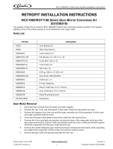
A
llow 6 “Clearance for Air Circulation
A proper installation locates the
ice machine indoors, but in a
place where the heat and noise it
produces are not objectionable.
Air cooled machines discharge
hot air out the
back and must
have a minimum of 6 inches of
clearance behind the ice
machine.
Space for maintenance access is
also important. If two units are
placed side by side on a bin, side
access becomes even more
important.
Two Units on One Bin
A
llow 6 “Clearance for Air Circulation

GEM0650/0956/1256 A/W For the Plumber
Page 7
Water Inlet:
●Air Cooled Models: The recommended water supply is clean, cold water. Use 3/8 inch O.D. copper tubing,
connect to the 3/8 inch male flare at the back of the cabinet. Install a hand valve near the machine to control
the water supply.
●Water Cooled Models: A separate 3/8 inch O.D. copper line is recommended, with a separate hand valve to
control it. Connect to the 3/8 inch FPT condenser inlet at the back of the cabinet. The water pressure to all
lines must always be above 20 psig, and below 80 psig.
●Water Treatment: In most areas, a water filter of some type will be useful. In areas where the water is
highly concentrated with minerals, the water should be tested by a water treatment specialist, and the
recommendations of the specialist regarding filtration and/or treatment should be followed.
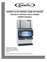
Drains:
●Air Cooled Models: Connect a rigid drain tube to the ¾ FPT drain fitting at the back of the cabinet. The
drain is a gravity type, and a ¼ inch per foot fall is the minimum acceptable pitch for the drain. There should
be a vent at the highest point of the drain line, and the ideal drain receptacle would be a trapped and vented
floor drain. Use only ¾ inch rigid tubing.
●Water Cooled Models: Connect a separate drain line to the ½ inch condenser drain connection at the back
of the cabinet. Do not vent this drain.
●Storage Bin: Connect a
separate gravity type drain line to the ice storage bin drain. Vent this drain if there is
a long horizontal run from the bin to the floor drain. Insulation of this drain line is recommended.
WATER COOLED MODELS
AIR COOLED MODELS
Floor Drain
Water Inlet
Vented Drain
Water Filter
Condenser Drain
Water In
Hand Valve
Bin Drain
Condenser Inlet
Water Filter
Hand Valve
Bin Drain
Condenser Drain
Vented Drain
Condenser Inlet
Vented Drain
Vented Drain
Water In

GEM0650/0956/1256 A/W For the Electrician
Page 8
Electrical Connections:
Check the ice machine nameplate (located on the back panel) for the voltage requirements, and minimum
circuit ampacity. The ice machine requires a solid chassis to earth ground.
Connect the ice machine to its own electrical circuit so it is individually fused. Voltage variation must remain
within the limitations, even under starting conditions.
Note: All external wiring must conform to national, state and local electrical codes.
The use of a licensed electrician is required to perform the electrical installation.
Electrical Inlet
Power
Supply
Water Cooled Models
Air Cooled Models

GEM0650/0956/1256A/W For the Installer
Page 9
Final Check List:
_______
1. Is the ice machine installed indoors in a location where the air and water temperatures are
controlled and where they do not exceed the design limitations?
_____2. Is there an electrical service disconnect within sight of the installed machine?
_____3. Has the voltage been checked and compared to the nameplate requirements?
_____4. Have all the plumbing connections been made and checked for leaks?
_____5. Is the ice machine and storage bin level?
_____6. Is there a minimum of 6 inches of clearance at the back of the machine for proper service
access and air circulation?
_____7. Is the water pressure a minimum of 20 psig?
_____8. Has the ice machine been secured to the bin?
_____9. Is there clearance over the top of the ice machine for service access?
____10. Is there a water shut off valve installed near the ice machine?
____11. Have all the shipping blocks been removed from the ice machine?
Insure the machine is level
Note: Fasten the ice machine
to the bin with the hardware
supplied with the ice machine

GEM0650/0956/1256 A/W Start Up
Page 10
Pre-Start Inspection:
1. Remove the front and side service panels.
2. Check that any shipping blocks have been removed.
3. Inspect the interior of the ice machine for loose screws or wires.
4. Check that no refrigerant lines are rubbing each other.
5. Check that the fan blades turn freely (Air Cooled).
6. Check that the unit is installed correctly according to the final check list on page 8.
Start Up:
1. Go through the pre-start inspection.
2. Open the hand valve, observe that water enters the water reservoir, fills the tube from the water
reservoir to the evaporator and then shuts off. (Water cooled only, Turn the water supply ON to the
water cooled condenser). Check for leaks.
3. Switch the master (mode) switch ON. The electrical start up sequence in automatic.
a. There should be a short (15 second) delay before the gear motor starts.
b. After the gear motor starts, the compressor will start.
4. On air cooled models, the condenser will begin to discharge warm air, on water cooled models, the
water regulating valve will open and warm water will be discharged into the drain.
5. The unit should soon be making ice, if desired; the low side pressure may be checked: it should be 32
psig +/- 2 psig.
The suction line temperature at the compressor is normally very cold, nearly to the point of frost up to
the compressor body, but not on it.
The air cooled discharge pressure will depend upon air and water temperatures, but should be between
200 psig and 280 psig.
The water cooled discharge pressure should be a constant at about 245 psig.
Note: The above pressures are for new, clean machines. You can expect to see some values higher,
and some lower between different units.
6. There are no adjustments to make, so replace the panels.
7. Clean and/or sanitize the storage bin interior, wipe off the exterior with a clean, damp cloth.
8. Give the owner/user the service manual, instruct him/her in the operation of the unit, and make sure
they know who to call for service.
9. Fill out the manufacturer’s registration and mail it to ICE-O-Matic.

GEM0650/0956/1256 A/W Component Description
Page 11
●Control Box: Contains the electrical controls that operate the machine.
●High Pressure Cut Out Switch: An auto-reset switch sensing the high side refrigeration pressure. It will
shut the machine off if the discharge pressure exceeds 450 psig.
●Low Pressure Cut Out Switch: An auto-reset switch sensing the low side refrigeration pressure. It will
disconnect power to the circuit board and shut down the machine if the low pressure falls too low.
●Evaporator: A vertical stainless steel tube, refrigerated and water filled. Utilizes a stainless steel auger.
●Compressor: The refrigerant vapor pump.
●Water Reservoir: Float operated, it maintains the water level in the evaporator at a constant level, and it
also contains the water level sensor.
●Water Level Sensor: Senses if there is water in the reservoir to make ice out of. Will shut the ice machine
off if there is no water in the reservoir.
●Ice Discharge Chute: Directs the ice produced by the evaporator into the storage bin.
●Ice Level Sensor: An “electronic eye”, it senses the presence of ice in the bottom of the discharge chute.
●Gear Motor: An oil filled, speed reduction gearbox, driving the auger.
●Drain Tube: When uncapped and lowered, drains the evaporator.
●Condenser: Air or water cooled, where the heat removed in ice making is discharged.
●Expansion Valve: The refrigerant metering device.
Ex
p
ansion Valve
Drain Tube
High
Pressure
Water Reservoir
Condenser
Control Box
Air Cooled Model Shown
Cut Out
Ice Level Sensor
Ice Discharge Chute
Compressor
Gear Motor

GEM0650/0956/1256 A/W Component Description
Page 12
●Contactor: A definite purpose contactor connecting the compressor and the fan motor to the power supply.
●Circuit Board: Controls the operation of the ice machine using input from the sensors and pressure controls.
Switches loads on and off thru relays. (Reference Photo Below)
●Potential Relay: The compressor start relay.
●Mode (ON/OFF) Switch: Manual control for the machine.
Control Board
Water OK Light
Power Light
Service Light
Freeze Light
Bin Full Light
LED3
LED1
Compressor Relay
Auger Relay

GEM0650/0956/1256 A/W Component Description
Page 13
●Evaporator: A refrigerated vertical tube filled with water and containing a water seal and auger.
●Auger: A solid stainless steel double spiral auger, it pushes the ice crystals up to the top of the evaporator.
●Water Seal: A two part “face” seal, the top half rotating with the auger, the bottom half stationary, the sealing
action being where the two “faces” meet.
●Ice Sweep: A plastic cap with “fingers”. It revolves with the auger to “sweep” the ice into the ice chute.
●Breaker (Divider): Where the ice is compressed and much of the extra water is squeezed out of it before it
is discharged into the bin.
●Motor: A split phase motor that drives the gear reducer.
●Thrust Bearings: As the ice is pushed up the evaporator, the auger is thrust down, and pressure from the
auger thrust is taken up by this bearing.
Evaporator
Auger
Breaker/Divider
Bearing
Ice Sweep
Motor
Water Seal

GEM0650/0956/1256 A/W Electrical Sequence
Page 14
Electrical Sequence:
There are 7 indicator lights on the control board:
●WTR-OK: (Water OK) Green. Normal=Glowing. Glow when there is water in the reservoir.
●PWR-OK: (Power OK) Green. Normal=Glowing. Glows when the power board has power and is functional.
●Service: Red. Normally Off.
●Freeze: Red. Normally glowing when making ice.
●Bin Full: Red. Normally Off when making ice.
●LED1: White. Located next to the Control Board’s Compressor Relay. Normally glowing when making ice.
●LED2: White. Located next to the Control Board’s Auger Motor Relay. Normally glowing when making ice.
If the machine is switched OFF at the mode switch, but otherwise ready to go, switching the mode switch ON
does the following:
●The PWR-OK light glows.
●If there is water in the float reservoir, the WTR-OK light glows.
●After 10 seconds the Freeze, LED1 and LED3 lights glow and the machine starts up.
Start Up:
●The compressor relay and auger motor relay become energized, connecting power to the windings of the
auger motor and contactor coil.
●The contactor is energized, connecting power to the compressor, and the compressor starts.
●As ice is made it passes between the ice level sensors but because it is not a continuous stream it only
interrupts the sensor’s infrared beam momentarily. The bin full light remains off and the machine stays on
until ice builds up in the bin and blocks the path between the sensors for 6 seconds or longer. When that
occurs the bin full light glows and the machine shuts down.
Shut Down:
●The compressor relays opens, LED1 goes out.
●The compressor contactor opens.
●The auger motor stays on for 1 more minute, clearing out ice in the evaporator, and then
●The auger motor relay opens, LED3 goes out and the auger motor stops.
The compressor will not restart until 2 minutes or more have passed after last shutdown. If the path between
the ice level sensors remains clear for more than 10 seconds the ice machine will restart.
Control Board Protection Devices:
●When the water level in the reservoir falls below the water level sensor’s tip, the WTR-OK light goes out and
the machine shuts down. When water refills the reservoir the WTR-OK light glows and the machine starts up
again.
●If the auger drive motor currents becomes excessive the compressor and auger drive motor will be switched
OFF and the Service light will blink. The control board will restart the auger drive motor in 4 minutes. If
during the first 60 seconds after restart the auger motor current stays within limits, the compressor is
restarted and the machine returns to normal operation. If the auger motor’s current is excessive within 60
seconds after restart, the process will be repeated once more. If during that try the current is still excessive
the machine shuts down and must be manually reset. The Service light will then be glowing continuously.
To Reset:
●Switch power to the unit off and then back on.
Other Protection Devices:
●If the high pressure control cut out switch opens the machine will stop immediately. It will automatically
reset when the high pressure falls below its cut in point.
●If the low pressure control cut out switch opens the machine will stop immediately. It will automatically reset
when the pressure rises above its cut in point.
●The mode (ON-OFF) switch is the manual control for the complete machine, but it is not a service
disconnect.
/