
SERVICE MANUAL
FRYMASTER BIRE14/MRE14 SERIES
E
4
ELECTRIC FRYER
Frymaster L.L.C., 8700 Line Avenue 71106
P.O. Box 51000, Shreveport, Louisiana 71135-1000
PHONE 318-865-1711 FAX 318-219-7135
PRINTED IN THE UNITED STATES SERVICE HOTLINE
1-800-24-FRYER APRIL 2006
www.frymaster.com email: service @frymaster.com *8196152*
FOR YOUR SAFETY
Do Not Store or use gasoline or other
flammable vapors and liquids in the
vicinity of this or any other appliance.
This equipment chapter is to be
installed in the Fryer Section of the
Equipment Manual.
MANUFACTURED
BY
P.O. BOX 51000
SHREVEPORT, LOUISIANA 71135-1000
PHONE: 1-318-865-1711
TOLL FREE: 1-800-551-8633
1-800-24 FRYER
FAX: 1-318-688-2200

NOTICE
IF, DURING THE WARRANTY PERIOD, THE CUSTOMER USES A PART FOR THIS ENODIS
EQUIPMENT OTHER THAN AN UNMODIFIED NEW OR RECYCLED PART PURCHASED
DIRECTLY FROM FRYMASTER DEAN, OR ANY OF ITS AUTHORIZED SERVICE CENTERS,
AND OR THE PART BEING USED IS MODIFIED FROM ITS ORIGINAL CONFIGURATION, THIS
WARRANTY WILL BE VOID. FURTHER, FRYMASTER DEAN AND ITS AFFILIATES WILL NOT
BE LIABLE FOR ANY CLAIMS, DAMAGES OR EXPENSES INCURRED BY THE CUSTOMER
WHICH ARISE DIRECTLY OR INDIRECTLY, IN WHOLE OR IN PART, DUE TO THE
INSTALLATION OF ANY MODIFIED PART AND/OR PART RECEIVED FROM AN
UNAUTHORIZED SERVICE CENTER.
NOTICE
This appliance is intended for professional use only and is to be operated by qualified
personnel only. A Frymaster Dean Factory Authorized Service Center (FASC) or other
qualified professional should perform installation, maintenance, and repairs. Installation,
maintenance, or repairs by unqualified personnel may void the manufacturer’s warranty.
NOTICE
This equipment must be installed in accordance with the appropriate national and local
codes of the country and/or region in which the appliance is installed.
DANGER
All wiring connections for this appliance must be made in accordance with the wiring
diagrams furnished with the equipment. Wiring diagrams are locted on the inside of the
fryer door.
NOTICE TO U.S. CUSTOMERS
This equipment is to be installed in compliance with the basic plumbing code of the
Building Officials and Code Administrators International, Inc. (BOCA) and the Food Service
Sanitation Manual of the U.S. Food and Drug Administration.
NOTICE TO OWNERS OF UNITS EQUIPPED WITH COMPUTERS
U.S.
This device complies with Part 15 of the FCC rules. Operation is subject to the following
two conditions: 1) This device may not cause harmful interference, and 2) This device must
accept any interference received, including interference that may cause undesired
operation. While this device is a verified Class A device, it has been shown to meet the
Class B limits.
CANADA
This digital apparatus does not exceed the Class A or B limits for radio noise emissions as
set out by the ICES-003 standard of the Canadian Department of Communications.
Cet appareil numerique n’emet pas de bruits radioelectriques depassany les limites de
classe A et B prescrites dans la norme NMB-003 edictee par le Ministre des Communcations
du Canada.

DANGER
Improper installation, adjustment, maintenance or service, and unauthorized alterations or
modifications can cause property damage, injury, or death. Read the installation, operating,
and service instructions thoroughly before installing or servicing this equipment.
DANGER
The front ledge of this appliance is not a step! Do not stand on the appliance. Serious
injury can result from slips or contact with the hot oil.
DANGER
Do not store or use gasoline or other flammable liquids or vapors in the vicinity of this or
any other appliance.
DANGER
The crumb tray in fryers equipped with a filter system must be emptied into a fireproof
container at the end of frying operations each day. Some food particles can spontaneously
combust if left soaking in certain shortening material.
WARNING
Do not bang fry baskets or other utensils on the fryer’s joiner strip. The strip is present to
seal the joint between the fry vessels. Banging fry baskets on the strip to dislodge
shortening will distort the strip, adversely affecting its fit. It is designed for a tight fit and
should only be removed for cleaning.
DANGER
Adequate means must be provided to limit the movement of this appliance without
depending on or transmitting stress to the electrical conduit. A restraint kit is provided with
the fryer. If the restraint kit is missing contact your local Frymaster Factory Authorized
Service Center (FASC) for part number 826-0900.
DANGER
This fryer has two power cords and prior to movement, testing, maintenance and any repair
on your Frymaster fryer; disconnect both electrical power cords from the electrical supply.
WARNING
Do not use water jets to clean this equipment.
i
i

ii
WARRANTY STATEMENT
Frymaster, L.L.C. makes the following limited warranties to the original purchaser only for this
equipment and replacement parts:
A. WARRANTY PROVISIONS - FRYERS
1. Frymaster L.L.C. warrants all components against defects in material and workmanship for a
period of one year.
2. All parts, with the exception of the frypot, heating elements and fuses, are warranted for one
year after installation date of fryer.
3. If any parts, except fuses and filter O-rings, become defective during the first year after
installation date, Frymaster will also pay straight-time labor costs to replace the part, plus up
to 100 miles/160 km of travel (50 miles/80 km each way).
B. WARRANTY PROVISIONS - FRYPOTS
(Applies to fryers manufactured after December 1, 2003, only.)
If a frypot develops a leak within ten years after installation, Frymaster will, at its option, either
replace the entire battery or replace the frypot, allowing up to the maximum time per the
Frymaster time allowance chart hours of straight-time labor plus up to 100 miles/160 km of
travel (50 miles/80 km each way) to change the frypot.
C. WARRANTY PROVISIONS - HEATING ELEMENTS
1. Frymaster L.L.C. warrants the heating elements against defective material or workmanship
for a period of three years from the original installation date, parts only.
2. This warranty does not cover ancillary components, including the high-limit, temperature
probe, and contactors.
D. WARRANTY PROVISIONS - COOKING COMPUTER
1. Frymaster L.L.C. warrants the M-2000 Cooking Computer against defective material or
workmanship for a period of one year from the original installation date, parts and labor.
Replacements for defective units during the second year include part only. Labor is charged
to the store during the second and third years. The third year, warranty will cover the part at a
reduced cost of $90.00.
2. During this warranty period, Frymaster will, at its option, repair or replace defective cooking
computer returned with new or factory rebuilt and functionally operative units.
3. For replacement of defective computers under warranty, call your local Frymaster Factory
Authorized Service Center. All computers replaced under the Frymaster exchange program
only carry the remaining original warranty.

iii
E. PARTS RETURN
All defective in-warranty parts must be returned to a Frymaster Authorized Factory Service
Center within 60 days for credit. After 60 days, no credit will be allowed.
F. WARRANTY EXCLUSIONS
This warranty does not cover equipment that has been damaged due to misuse, abuse, alteration,
or accident such as:
• improper or unauthorized repair (including any frypot which is welded in the field);
• failure to follow proper installation instructions and/or scheduled maintenance procedures as
prescribed in your MRC cards. Proof of scheduled maintenance is required to maintain the
warranty;
• improper maintenance;
• damage in shipment;
• abnormal use;
• removal, alteration, or obliteration of either the rating plate or the date code on the heating
elements;
• operating the frypot without shortening or other liquid in the frypot;
• no fryer will be warranted under the ten-year program for which a proper start-up form has not
been received.
This warranty also does not cover:
• transportation or travel over 100 miles/160 km (50 miles/80 km each way), or travel over two
hours;
• overtime or holiday charges;
• consequential damages (the cost of repairing or replacing other property which is damaged), loss
of time, profits, use or any other incidental damages of any kind.
There are no implied warranties of merchantability or fitness for any particular use or purpose.
This warranty is applicable at the time of this printing and is subject to change.

iv
ELECTRICAL POWER SPECIFICATIONS
VOLTAGE PHASE
WIRE
SERVICE
MINIMUM WIRE
SIZE
AWG (mm)
AMPS
(per leg)
208 Single 3 3 (5.83) 68
208 3 3 6 (4.11) 39
240 Single 3 4 (5.19) 59
240 3 3 6 (4.11) 34
480 Single 3 8 (3.26) 30
480 3 3 8 (2.59) 17
220/380 3 4 6 (4.11) 21
240/415 3 4 6 (4.11) 20
230/400 3 4 6 (4.11) 21

v
BIRE14/MRE14 SERIES E
4
ELECTRIC FRYERS
TABLE OF CONTENTS
CAUTIONARY STATEMENTS.......................................................................................................................i
WARRANTY STATEMENT .......................................................................................................................... ii
ELECTRICAL POWER SPECIFICATIONS...............................................................................................iv
CHAPTER 1: Service Procedures
1.1 General........................................................................................................................................... 1-1
1.2 Replacing a Controller................................................................................................................... 1-1
1.3 Replacing Component Box Components....................................................................................... 1-1
1.4 Replacing a High-Limit Thermostat .............................................................................................. 1-3
1.5 Replacing a Temperature Probe..................................................................................................... 1-3
1.6 Replacing a Heating Element......................................................................................................... 1-5
1.7 Replacing Contactor Box Components..........................................................................................1-6
1.8 Replacing a Frypot......................................................................................................................... 1-7
1.9 Built-In Filtration System Service Procedures...............................................................................1-9
1.9.1 Filtration System Problem Resolution........................................................................... 1-9
1.9.2 Replacing the Filter Motor, Filter Pump and Related Components............................. 1-10
1.9.3 Replacing the Filter Transformer or Filter Relay ........................................................ 1-12
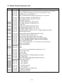
1.10 Interface Board Diagnostic Chart ................................................................................................ 1-13
1.11 Probe Resistance Chart ................................................................................................................ 1-14
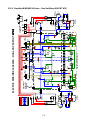
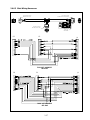
1.12 Wiring Diagrams.......................................................................................................................... 1-15
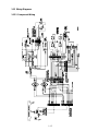
1.12.1 Component Wiring ...................................................................................................... 1-15
1.12.2 Tilt Switch Wiring....................................................................................................... 1-16
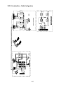
1.12.3 Contactor Box-Delta Configuration............................................................................. 1-17
1.12.4 Contactor Box-WYE Configuration............................................................................ 1-18
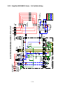
1.12.5 Simplified Full-Vat Delta Wiring................................................................................ 1-19
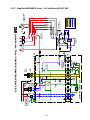
1.12.6 Simplified Dual-Vat Delta Wiring............................................................................... 1-20
1.12.7 Simplified Full-Vat Export WYE Wiring.................................................................... 1-21
1.12.8 Simplified Dual-Vat Export WYE Wiring .................................................................. 1-22
1.12.9 Simplified Full-Vat EPRI Wiring................................................................................ 1-23
1.12.10 Simplified Full-Vat EPRI Wiring Export WYE Wiring.............................................. 1-24
CHAPTER 2: Parts List
2.1 Accessories .................................................................................................................................... 2-1
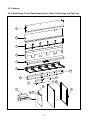
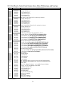
2.2 Cabinetry ....................................................................................................................................... 2-2
2.2.1 Backs, Control Panel Frames, Doors, Sides, Tilt Housings and Top Caps ................... 2-2
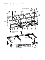
2.2.2 Cabinet Bases, Braces and Associated Parts ................................................................. 2-4
2.3 Drain System Components............................................................................................................. 2-6
2.3.1 Drain Tube Sections and Associated Parts.................................................................... 2-6
2.3.2 Drain Valves and Associated Parts (Units with Built-In Filtration).............................. 2-8
2.3.3 Drain Valves and Associated Parts (Units without Built-In Filtration)....................... 2-12
2.4 Electronics and Electrical Components ....................................................................................... 2-13
2.4.1 Component Boxes........................................................................................................ 2-13
2.4.2 Contactor Boxes........................................................................................................... 2-15
2.4.3 Terminal Blocks........................................................................................................... 2-19
2.4.4 Heating Element Assemblies and Associated Parts..................................................... 2-20
2.4.4.1 Element Assemblies and Hardware............................................................. 2-20
2.4.4.2 Element Tube Assemblies ........................................................................... 2-22
2.4.5 Computers.................................................................................................................... 2-23
2.4.6 Wiring.......................................................................................................................... 2-24
2.4.6.1 Contactor Box Wiring Assemblies 12-Pin Dual Vat................................... 2-24
2.4.6.2 Contactor Box Wiring Assemblies 12-Pin Full Vat .................................... 2-25
2.4.6.3 Contactor Box Wiring Assemblies 6-Pin Left Element............................... 2-26

vi
BIRE14/MRE14 SERIES E
4
ELECTRIC FRYERS
TABLE OF CONTENTS cont.
2.4.6.4 Contactor Box Wiring Assemblies 9-Pin Right Element.............................2-26
2.4.6.5 Main Wiring Harnesses................................................................................2-27
2.4.6.6 Component Box and Filter Pump Wiring Harnesses ...................................2-28
2.4.6.7 Component Box to Filter Pump Harnesses ..................................................2-28
2.4.6.8 Interface Board to Controller Wiring Harness 15-Pin..................................2-29
2.5 Filtration System Components.....................................................................................................2-30
2.6 Frypots and Associated Components ...........................................................................................2-33
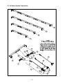
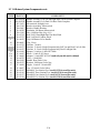
2.7 Oil Return System Components...................................................................................................2-35
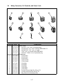
2.8 Wiring Connectors, Pin Terminals and Power Cords...................................................................2-37
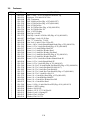
2.9 Fasteners.......................................................................................................................................2-38

1-1
BIRE14/MRE14 SERIES E
4
ELECTRIC FRYERS
CHAPTER 1: SERVICE PROCEDURES
1.1 General
Before performing any maintenance on your Frymaster fryer, disconnect the fryer from the electrical
power supply.
WARNING
To ensure the safe and efficient operation of the fryer and hood, the electrical plug
for the 120-volt line, which powers the hood, must be fully engaged and locked in its
pin and sleeve socket.
When electrical wires are disconnected, it is recommended that they be marked in such a way as to
facilitate re-assembly.
1.2 Replacing a Computer
1. Disconnect the fryer from the electrical power supply.
2. The controller bezel is held in place by tabs at the top and bottom. Slide the metal bezel up to
disengage the lower tabs. Then slide the bezel down to disengage the upper tabs.
3. Remove the two screws from the upper corners of the control panel. The control panel is hinged
at the bottom and will swing open from the top.
4. Unplug the wiring harness from the connector on the back of the computer and disconnect the
grounding wire from terminal adjacent to the connector. Remove the control panel assembly by
lifting it from the hinged slots in the control panel frame.
5. Remove the controller from the control panel assembly and install the replacement computer.
Reinstall the control panel assembly by reversing steps 1 and 2.
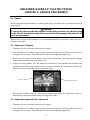
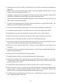
1.3 Replacing Component Box Components
1. Disconnect the fryer from the electrical power supply.
2. The controller bezel is held in place by tabs at the top and bottom. Slide the metal bezel up to
disengage the lower tabs. Then slide the bezel down to disengage the upper tabs.
Ground Wire Terminal
15-Pin Connecto
r

1-2
3. Remove the two screws from the upper corners of the control panel and allow the control panel
to swing down.
4. Unplug the wiring harness from the 15-pin connector on the interface board and disconnect the
grounding wire from terminal adjacent to the 15-pin connector on the back of the controller.
Remove the control panel assembly by lifting it from the hinge slots in the control panel frame.
5. Disconnect the wiring from the component to be replaced, being sure to make a note of where
each wire was connected.
6. Dismount the component to be replaced and install the new component, being sure that any
required spacers, insulation, washers, etc. are in place.
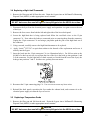
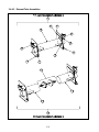
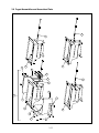
NOTE: If more room to work is required, the control panel frame assembly may be removed by
removing the hex head screws that secure it to the fryer cabinet (see illustration below). If this
option is chosen, all control panel assemblies must be removed per steps 1 and 2 above. The
cover plate on the lower front of the component box may also be removed if desired. Removing
the component box itself from the fryer is not recommended due to the difficulty involved in
disconnecting and reconnecting the oil-return valve rods, which pass through openings in the
component box.
Remove these three
screws at each end.
Remove these two screws
from the center supports.
Removing the Control Panel Frame and Top Cap Assembly
7. Reconnect the wiring disconnected in step 3, referring to your notes and the wiring diagrams on
the fryer door to ensure that the connections are properly made. Also, verify that no other wiring
was disconnected accidentally during the replacement process.
8. Reverse steps 1 through 4 to complete the replacement and return the fryer to service.

1-3
1.4 Replacing a High-Limit Thermostat
1. Remove the filter pan and lid from the unit. Drain the frypots into an McDonald’s Shortening
Disposal Unit (MSDU) or other appropriate metal container.
DANGER
DO NOT drain more than one full frypot or two split frypots into the MSDU at one time.
2. Disconnect the fryer from the electrical power supply and reposition it to gain access to the rear
of the fryer.
3. Remove the four screws from both the left and right sides of the lower back panel.
4. Locate the high-limit that is being replaced and follow the two-black wires to the 12-pin
connector C-6. Note where the leads are connected prior to removing them from the connector.
Unplug the 12-pin connector C-6 and using a pin-pusher push the pins of the high-limit out of
the connector.
5. Using a wrench, carefully unscrew the high-limit thermostat to be replaced.
6. Apply Loctite
™
PST 567 or equivalent sealant to the threads of the replacement and screw it
securely into the frypot.
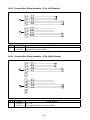
7. Insert the leads into the 12-pin connector C-6 (see illustration below). For full-vat units or the
left half of a dual-vat unit (as viewed from the rear of the fryer) the leads go into positions 1 and
2 of the connector. For the right half of a dual-vat unit (as viewed from the rear of the fryer), the
leads go into positions 7 and 8. In either case, polarity does not matter.
8. Reconnect the 12-pin connecting plug C-6. Use wire ties to secure any loose wires.
9. Reinstall the back panels, reposition the fryer under the exhaust hood, and reconnect it to the
electrical power supply to return the fryer to service.
1.5 Replacing a Temperature Probe
1. Remove the filter pan and lid from the unit. Drain the frypots into a McDonald’s Shortening
Disposal Unit (MSDU) or other appropriate metal container.
DANGER
DO NOT drain more than one full frypot or two split frypots into the MSDU at one time.

1-4
2. Disconnect the fryer from the electrical power supply and reposition it to gain access to the rear
of the fryer.
3. Remove the four screws from both sides of the lower back panel. Then remove the two screws
on both the left and right sides of the back of the tilt housing. Lift the tilt housing straight up to
remove from the fryer.
4. Locate the red and white wires of the temperature probe to be replaced. Note where the leads
are connected prior to removing them from the connector. Unplug the 12-pin connector C-6 and
using a pin-pusher push the pins of the temperature probe out of the connector.
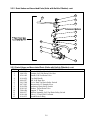
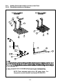
5. Raise the element and remove the securing probe bracket and metal tie wraps that secure the
probe to the element (see illustration below).
6. Gently pull on the temperature probe and grommet, pulling the wires up the rear of the fryer and
through the element tube assembly.
7. Insert the replacement temperature probe (wires first) into the tube assembly ensuring that the
grommet is in place. Secure the probe to the elements using the bracket which was removed in
Step 5 and the metal tie wraps which were included in the replacement kit.
8. Route the probe wires out of the tube assembly following the element wires down the back of the
fryer through the Heyco bushings to the 12-pin connector C-6. Secure the wires to the sheathing
with wire ties.
9. Insert the temperature probe leads into the 12-pin connector C-6 (see illustration below). For
full-vat units or the right half of a dual-vat unit (as viewed from the rear of the fryer) the red lead
goes into position 3 and the white lead into position 4 of the connector. For the left half of a
dual-vat unit (as viewed from the rear of the fryer), the red lead goes into position 9 and the
white lead into position 10. NOTE: Right and left refer to the fryer as viewed from the rear.

1-5
10. Secure any loose wires with wire ties making sure that the lead wires will not interfere with the
movement of the springs. Rotate the elements up and down making sure that movement is not
restricted and that the wires are not pinched.
11. Reinstall the tilt housing and back panels, reposition the fryer under the exhaust hood, and
reconnect it to the electrical power supply to return the fryer to service.
1.6 Replacing a Heating Element
1. Perform steps 1-3 of section 1.5, Replacing a Temperature Probe.
2. On dual-vat fryers, and on full-vat fryers where the temperature probe is attached to the element
being replaced, disconnect the wire harness containing the probe wiring. Using a pin pusher,
disconnect the probe wires from the 12-pin connector C-6.
3. In the rear of the fryer directly behind the frypot disconnect the 6-pin connector for the left
element (as viewed from the front of the fryer) or the 9-pin connector for the right element.
Press in on the tabs on each side of the connector while pulling outward on the free end to extend
the connector and release the element leads (see photo below). Pull the leads out of the
connector and out of the wire sleeving.
4. Raise the element to the full up position and support the elements.
5. Remove the hex head screws and nuts that secure the element to the tube assembly and pull the
element out of the frypot. NOTE: Full-vat elements consist of two dual-vat elements clamped
together. For full-vat units, remove the element clamps before removing the nuts and screws that
secure the element to the tube assembly.
6. If applicable, recover the probe bracket and probe from the element being replaced and install
them on the replacement element. Install the replacement element in the frypot, securing it with
the nuts and screws removed in Step 5 to the tube assembly. Ensure the gasket is between the
tube and element assembly.
7. Route the element leads through the element tube assembly and into the wire sleeving to prevent
chafing. Ensure that the wire sleeving is routed back through the Heyco bushing keeping it clear
from the lift springs. Also ensure that the wire sleeving extends into the tube assembly to protect
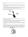
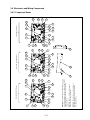
the edge of the tube assembly from chafing the wires. Press the pins into the connector in
accordance with the diagram on the following page, and then close the connector to lock the

1-6
leads in place. NOTE: It is critical that the wires be routed through the sleeving to prevent
chafing.
1
4
2
5
3
6
1
4
2
5
3
6
789
5
R
4R
6
R
1R
2
R
3R
Index Marker marks
Position 1
5L 4L6L 1L2L3L
8. Reconnect the element connector ensuring that the latches lock.
9. Insert the temperature probe leads into the 12-pin wiring harness connector C-6 (see illustration
below). For full-vat units or the right half of a dual-vat unit, the red lead goes into position 3 and
the white into position 4. For the left half of a dual-vat unit, the red lead goes into position 9 and
the white into position 10. NOTE: Right and left refer to the fryer as viewed from the rear.
10. Reconnect the 12-pin connector C-6 of the wiring harness disconnected in Step 2.
11. Lower the element down onto the basket rack.
12. Reinstall the tilt housing and back panels, reposition the fryer under the exhaust hood, and
reconnect it to the electrical power supply.
1.7 Replacing Contactor Box Components
1. If replacing a contactor box component above the built-in filter system, remove the filter pan and
lid from the unit. Drain the frypots into a McDonald’s Shortening Disposal Unit (MSDU) or
other appropriate metal container. If replacing a contactor box component in a non-filter unit or
a frypot that’s not over the filter pan, drain the frypot above the box into a McDonald’s
Shortening Disposal Unit (MSDU) or other appropriate metal container.
DANGER
DO NOT drain more than one full frypot or two split frypots into the MSDU at one time.

1-7
2. Disconnect the fryer from the electrical power supply.
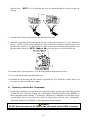
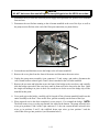
3. Remove the two screws securing the cover of the contactor box. The contactor boxes above the
filter pan are accessed by sliding under the fryer. They are located to the left and right above the
guide rails (see photo below). The contactor boxes of non-filter units or frypots not over the
filter pan are accessed by opening the fryer door directly under the affected frypot.
4. The contactors and relays are held on by threaded pin studs so that only removal of the nut is
required to replace the component.
5. After performing necessary service, reverse steps 1-4 to return the fryer to operation.
Left and right views of mechanical contactor box components.
1.8 Replacing a Frypot
1. Drain the frypot into the filter pan or, if replacing a frypot over the filter system, into a
McDonald’s Shortening Disposal Unit (MSDU) or other appropriate metal container. If
replacing a frypot over the filter system, remove the filter pan and lid from the unit.
DANGER
DO NOT drain more than one full frypot or two split frypots into the MSDU at one time.
2. Disconnect the fryer from the electrical power supply and reposition it to gain access to both the
front and rear.
Remove two screws to access contactor box components above the filter
pan
.

1-8
3. Slide the metal bezel up to release the bottom tabs, then slide the bezel down to disengage the
upper tabs.
4. Remove the two screws from the upper corners of the control panels and allow them to swing
down (see illustration and photo on page 1-1).
5. Unplug the wiring harnesses and ground wires from the backs of the controllers. Remove the
controllers by lifting them from the hinge slots in the control panel frame.
6. Remove the tilt housing and back panels from the fryer. The tilt housing must be removed first in
order to remove the upper back panel.
7. To remove the tilt housing remove the hex head screws from the rear edge of the housing. The
housing can be lifted straight up and off the fryer.
8. Remove the control panel by removing the screw in the center and the nuts on both sides.
9. Loosen the component boxes by removing the screws, which secure them in the cabinet.
10. Dismount the top cap by removing the nuts at each end that secure it to the cabinetry.
11. Remove the hex head screw that secures the front of the frypot to the cabinet cross brace.
12. Remove the top-connecting strip that covers the joint with the adjacent frypot.
13. Unscrew the Teflon vent/vacuum-breaker tube fitting, unscrew the nut located on the front of
each section of drain tube, and remove the tube assembly from the fryer.
14. Remove the covers from the drain safety switch(es) and disconnect the switch wiring at the
switch(es).
15. At the rear of the fryer, unplug the 12-pin connector C-6 and, using a pin pusher, disconnect the
high-limit thermostat leads.
16. Disconnect the oil return flexline(s) at the frypot end(s).
17. Raise the elements to the “up” position and disconnect the element springs.
18. Remove the machine screws and nuts that secure the element tube assembly to the frypot.
Carefully lift the element assembly from the frypot and secure it to the cross brace on the rear of
the fryer with wire ties or tape.
19. Carefully lift the frypot from the fryer and place it upside down on a stable work surface.
20. Recover the drain valve(s), oil return flexline connection fitting(s), and high-limit thermostat(s)
from the frypot. Clean the threads and apply Loctite
™
PST 567 or equivalent sealant to the
threads of the recovered parts and install them in the replacement frypot.
21. Carefully lower the replacement frypot into the fryer. Reinstall the hex head screw removed in
step 7 to attach the frypot to the fryer.

1-9
22. Position the element tube assembly in the frypot and reinstall the machine screws and nuts
removed in step 14.
23. Reconnect the oil return flexlines to the frypot, and replace aluminum tape, if necessary, to
secure heater strips to the flexlines.
24. Insert the high-limit thermostat leads disconnected in step 13 (see illustration on page 1-3 for pin
positions).
25. Reconnect the drain safety switch wiring to the switch(es) in accordance with the diagram below
then reinstall the switch covers.
26. Reinstall the drain tube assembly.
27. Reinstall the top connecting strips, top cap, tilt housing and back panels.
28. Reinstall controllers in the control panel frame and reconnect the wiring harnesses and ground
wires.
29. Reposition the fryer under the exhaust hood and reconnect it to the electrical power supply.
1.9 Built-in Filtration System Service Procedures
1.9.1 Filtration System Problem Resolution
One of the most common causes of filtration problems is placing the filter paper on the bottom of the
filter pan rather than over the filter screen.
CAUTION
Ensure that filter screen is in place prior to filter paper placement and filter pump
operation. Improper screen placement is the primary cause of filtration system
malfunction.
Whenever the complaint is “the pump is running, but no oil is being filtered,” check the installation
of the filter paper, and ensure that the correct size is being used. While you are checking the filter
paper, verify that the O-rings on the pick-up tube of the filter pan are in good condition. A missing
or worn O-rings allow the pump to take in air and decrease its efficiency.

1-10
If the pump motor overheats, the thermal overload will trip and the motor will not start until it is
reset. If the pump motor does not start, press the red reset switch (button) located on the rear of the
motor.
If the pump starts after resetting the thermal overload switch, then something is causing the motor to
overheat. A major cause of overheating is when several frypots are filtered sequentially, overheating
the pump and motor. Allow the pump motor to cool at least 30 minutes before resuming operation.
Pump overheating can be caused by:
• Solidified shortening in the pan or filter
lines, or
• Attempting to filter unheated oil or
shortening (cold oil and shortening are
more viscous, overloading the pump
motor and causing it to overheat).
If the motor runs but the pump does not return
oil, there is a blockage in the pump. Incorrectly
sized or installed paper/pads will allow food
particles and sediment to pass through the filter
pan and into the pump. When sediment enters
the pump, the gears bind, causing the motor to
overload, again tripping the thermal overload.
Shortening that has solidified in the pump will
also cause it to seize, with the same result.
A pump seized by debris or hard shortening can
usually be freed by manually moving the gears
with a screwdriver or other instrument.
Disconnect power to the filter system, remove the input plumbing from the pump, and use a
screwdriver to manually turn the gears.
● Turning the pump gears in reverse will release a hard particle.
● Turning the pump gears forward will push softer objects and solid shortening through the
pump and allow free movement of the gears.
Incorrectly sized or installed paper/pads will also allow food particles and sediment to pass through
and clog the suction tube on the bottom of the filter pan. Particles large enough to block the suction
tube may indicate that the crumb tray is not being used. Pan blockage can also occur if shortening is
left in the pan and allowed to solidify. Blockage removal can be accomplished by forcing the item
out with an auger or drain snake. Compressed air or other pressurized gases should not be used to
force out the blockage.
1.9.2 Replacing the Filter Motor, Filter Pump, and Related Components
1. Remove the filter pan and lid from the unit. Drain the frypots into a McDonald’s Shortening
Disposal Unit (MSDU) or other appropriate metal container.
Sediment Particle
Oil Flow
Up for reverse
Down for forward
Sediment Particle

1-11
DANGER
DO NOT drain more than one full frypot or two split frypots into the MSDU at one time.
2. Disconnect the fryer from the electrical power supply and reposition it to gain access to both the
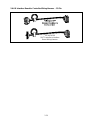
front and rear.
3. Disconnect the two flexlines running to the oil-return manifold at the rear of the fryer as well as
the pump suction flexline at the end of the filter pan connection (see photo below).
Disconnect flexlines indicated by the arrows.
4. Loosen the nut and bolt that secures the bridge to the oil-return manifold.
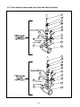
5. Remove the cover plate from the front of the motor and disconnect the motor wires.
6. Unplug the pump motor assembly 6-pin connector C-2 and, using a pin pusher, disconnect the
vent vacuum-breaker solenoid (pins 2 and 5) that is attached to the oil return manifold.
7. Remove the two nuts and bolts that secure the front of the bridge to the cross brace and carefully
slide the bridge rearward off the cross brace until its front end can be lowered to the floor. Undo
the single nut holding it in place in back. Be careful not to let the rear of the bridge slip off the
manifold at this point.
8. Get a good grip on the bridge, carefully pull it forward off the oil-return manifold, and lower the
entire assembly to the floor. Once on the floor, pull the assembly out the front of the fryer.
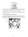
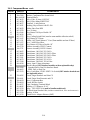
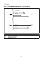
9. When required service has been completed, reverse steps 6-12 to reinstall the bridge. NOTE:
The black motor wires go on the top terminal, the white on the bottom. The pump solenoid valve
wires go in positions 1 and 4 of the 6-pin connector C-2; the vent vacuum-breaker solenoid valve
wires go in positions 2 and 5; the red/black heater tape wires go into position 3 and the
violet/white wires go into position 6 (see illustration below).

1-12
10. Reconnect the unit to the electrical power supply, and verify that the pump is functioning
correctly (i.e., when a filter handle is placed in the ON position, the motor should start and there
should be strong suction at the intake fitting and outflow at the rear flush port.)
11. When proper operation has been verified, reinstall the back panels and the filter pan and lid.
12. Reposition the fryer under the exhaust hood and reconnect it to the electrical power supply to
return the fryer to service.
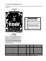
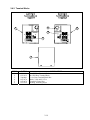
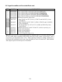
1.9.3 Replacing the Filter Transformer or Filter Relay
Disconnect the fryer from the electrical power supply. Remove the left controller from the fryer to
expose the interior of the left component box. The filter transformer and relay are located as shown
in the illustration below. NOTE: The right component box is identical to the left except that the
filter transformer and relay are not present.
Filter
Relay
Filter
Transformer
Dual-vat configuration illustrated. In full-vat units, left filter handle is not present.
Page is loading ...
Page is loading ...
Page is loading ...
Page is loading ...
Page is loading ...
Page is loading ...
Page is loading ...
Page is loading ...
Page is loading ...
Page is loading ...
Page is loading ...
Page is loading ...
Page is loading ...
Page is loading ...
Page is loading ...
Page is loading ...
Page is loading ...
Page is loading ...
Page is loading ...
Page is loading ...
Page is loading ...
Page is loading ...
Page is loading ...
Page is loading ...
Page is loading ...
Page is loading ...
Page is loading ...
Page is loading ...
Page is loading ...
Page is loading ...
Page is loading ...
Page is loading ...
Page is loading ...
Page is loading ...
Page is loading ...
Page is loading ...
Page is loading ...
Page is loading ...
Page is loading ...
Page is loading ...
Page is loading ...
Page is loading ...
Page is loading ...
Page is loading ...
Page is loading ...
Page is loading ...
Page is loading ...
Page is loading ...
Page is loading ...
Page is loading ...
Page is loading ...
Page is loading ...
-
 1
1
-
 2
2
-
 3
3
-
 4
4
-
 5
5
-
 6
6
-
 7
7
-
 8
8
-
 9
9
-
 10
10
-
 11
11
-
 12
12
-
 13
13
-
 14
14
-
 15
15
-
 16
16
-
 17
17
-
 18
18
-
 19
19
-
 20
20
-
 21
21
-
 22
22
-
 23
23
-
 24
24
-
 25
25
-
 26
26
-
 27
27
-
 28
28
-
 29
29
-
 30
30
-
 31
31
-
 32
32
-
 33
33
-
 34
34
-
 35
35
-
 36
36
-
 37
37
-
 38
38
-
 39
39
-
 40
40
-
 41
41
-
 42
42
-
 43
43
-
 44
44
-
 45
45
-
 46
46
-
 47
47
-
 48
48
-
 49
49
-
 50
50
-
 51
51
-
 52
52
-
 53
53
-
 54
54
-
 55
55
-
 56
56
-
 57
57
-
 58
58
-
 59
59
-
 60
60
-
 61
61
-
 62
62
-
 63
63
-
 64
64
-
 65
65
-
 66
66
-
 67
67
-
 68
68
-
 69
69
-
 70
70
-
 71
71
-
 72
72


Ask a question and I''ll find the answer in the document
Finding information in a document is now easier with AI
Related papers


Other documents
-
Henny Penny HC-934 Installation guide
-
SPT 30209 Operating instructions
-
 DV8 OFFROAD TTJK-01 Installation guide
-
Bennett Marine ES2000 User manual
-
JONARD TOOLS MF-5-25 Operating instructions
-
Scotsman Changing the Control Board from its Original Configuration to the AutoSentry System - 17-2813-01 Operating instructions
-
Pitco Frialator ME14S-C/MFD User manual
-
Ortech OT-96D User manual
-
-
SunStar 43274020 Owner's manual
