Page is loading ...

SERVICE MANUAL Colour Television
Product Code: 13007604
13007605
Original Version
Chassis Series: LA6-A
BC2E
FILE NO.
Model No. C21LF41
C21LF41B
Service Ref. No. C21LF41-00
C21LF41B-00
(Argentina)
Give complete “SERVICE REF. NO.” for
parts order or servicing. It is shown on the
rating plate at the cabinet back of the unit.
This T.V. receiver will not work properly in
foreign countries where the television trans-
mission system and power source differ from
the design specifications. Refer to the speci-
fication table.
Specifications
Power Source . . . . . . . . . AC220V, 50Hz / 60Hz
Receiving System . . . . . . PAL (M/M, N/N), NTSC (M/M)
Channel Coverage
Antenna mode VHF: CH02-CH13, UHF: CH14-CH69
CATV mode VHF band: CH01-CH13, Mid band: CH14-CH22
Super band: CH23-CH36, Hyper band: CH37-CH64
Ultra band: CH65-CH94 and CH100-CH125
Low mid band: CH95-CH99
Aerial Input Impedance . . 75
Input Terminals
AV1 (Video): Phono jack ✕ 1
AV1 (Audio): Phono jack (R/L) ✕ 1 set
AV2 (Video): Phono jack ✕ 1
AV2 (Audio): Phono jack (R/L) ✕ 1 set
Output Terminals
Video Monitor Output: Phono jack ✕ 1
Audio Monitor Output: Phono jack (R/L) ✕ 1
Headphone Jack: Mini stereo jack ✕ 1
Sound Output (RMS) . . . . 3W + 3W
Speakers . . . . . . . . . . . 5cm x 9cm x 2 pcs.
Dimensions . . . . . . . . . 596(W) X 493(H) X462(D) mm
Weight . . . . . . . . . . . . . approx. 22 Kg
Specifications subject to change without notice.
йȉǯNjNJÎࠔÏǯǞnjțശ
JXMRR
POWER

-8-
Service Adjustments
M
E
N
U
MENU
MENU
S1.11100101 S2.11111000
ADDRESS DATA
02 H-PHA 08
Item No.
Item
Data value
General
This set has an On-screen Service Menu system included in the CPU that allows remote operation for most of the
service adjustments.
2. Service Adjustments:
Press the CHANNEL UP or CHANNEL DOWN
button on the remote control handset to select the
desired service menu item you want to adjust.
Use the VOLUME + or
-
to adjust the data. The + or
-
button will increase or decrease the data
sequentially.
3. Exit from the Service Menu
Press the MENU button to turn off the Service Menu
display.
The data which is set in the service mode is stored
into the memory IC automatically.
[ Service Mode Display ]
Service Adjustment-1
1. Enter the Service Menu
While pressing the MENU button on the television, press the Number Key 2 on the remote control unit.
The Service Menu now appear.
IC802 (EEPROM) Replacement
When IC802 (EEPROM) is replaced, IC801 (CPU) will automatically write the initial reference data into IC802 for basic TV operation.
However, the bus data should be checked and some bus data should be set up before attempting the service adjustments. (See
pages 9 ~ 10 for detailed information.)
йȉǯNjNJÎࠔÏǯǞnjțശ
йȉǯNjNJÎࠔÏǯǞnjțശ
VOLUME +
VOLUME
-
CHANNEL UP
CHANNEL DOWN

-9-
Service Adjustments
On-screen Service Menu
Following table shows the initial values which have been stored in the CPU ROM, and items for the service adjustments.
When IC802 (EEPROM) is replaced, check the bus data to confirm they are the same as below. The shaded menu should be
checked and be set up or readjusted according to the procedures described in the following pages.
Initial Setup Data marked with an * should be changed from Initial Value Data.
No Item Initial value Range Description
1 RFAGC 13 00~63 RF AGC adjustment
2 H-PHA 12 00~31 H-PHASE adjustment(50Hz)
3 V-DC 28 00~63 V-POSITION adjustment(50Hz)
4 V-SIZ 79 00~127 V-SIZE adjustment(50Hz)
5 V-SCO 18 00~31 Vertical-S compensation(50Hz)
6 V-LIN 15 00~31 Vertical linearity adjustment(50Hz)
7 H-P60 +3 -16~+15 Difference value of H-PHASE adjustment(60Hz)
8 V-P60 0 -32~+31 Difference value of V-POSITION adjustment(60Hz)
9 V-S60 0 -64~+63 Difference value of V-SIZE adjustment(60Hz)
10 VSC60 0 -16~+15 Difference value of Vertical-"S" compensation(60Hz)
11 VLI60 0 -16~+15 Difference value of Vertical linearity adjustment(60Hz)
12 OSDHP 37 01~255 OSD horizontal remark position
13 OSDC 04 00~07 OSD Contrast
14 V-SCP 03 0~7 V-SIZE COMP
15 SBIAS 31 00~127 Sub Bias adjustment
16 RBIAS 00 00~255 Red Bias adjustment
17 GBIAS 00 00~255 Green Bias adjustment
18 BBIAS 00 00~255 Blue Bias adjustment
19 RDRIV 64 00~127 Red Drive adjustment
20 GDRIV 08 00~15 Green Drive adjustment
21 BDRIV 64 00~127 Blue Drive adjustment
22 White balance (a lateral line)
23 DRV Bright and Dark of White balance adjustment
24 B-YD 11 00~15 B-Y DC Level
25 R-YD 11 00~15 R-Y DC Level
26 B-YDN 0 -16~+15 Difference value of NTSC B-Y DC Level
27 R-YDN 0 -16~+15 Difference value of NTSC
R-Y DC Level
28 G-YA 00 00~01 G-Y Angle
29 RBGB 10 00~15 R-Y/ B-Y Gain Balance
30 RBAG 08 00~15 R-Y/ B-Y Angle
31 G-YAN 00 00~01 NTSC G-Y Angle
32 RBGBN -8 -8
~
+7 Difference value of NTSC R-Y/ B-Y Gain Balance
33 RBAGN +4 -8
~
+7 Difference value of NTSC R-Y/ B-Y Angle
34 COGV 03 00~03 Coring Gain
35 BLKS 00 00~03 Blk.str.start(W/Defeat)

-10-
Service Adjustments
No Item Initial value Range Description
36 BLKG 00 00~03 Blk.STR.gain
37 BRTA 00 00~01 Brt. Abl. Def
38 BRST 00 00~01 Mid. Stp. Def
39 BRTH 00 00~07 Bright. Abl. Threshold
40 WPL 00 00~03 WPL Ope. Point (W/ Defeat)
41 YGAM 00 00~03 Y Gamma Start
42 PRES 02 00~03 AV Mode Pre Shoot adj
43 OVERS 03 00~03 AV Mode Over Shoot adj
44 RFCO +1 -2
~
+1 Difference value of RF Coring Gain
45 PRESN 00 00~03 RF Mode Pre Shoot adj
46 OVERSN 03 00~03 RF Mode Over Shoot adj
47 TINT 0 -16~+15 Tint
48 SHRF +5 -16~+15 Difference value of RF sharpness
49
RFCOL +10
-16
~
+15
Difference value of TV color
50 TEXC +2 -4~+3 OSD TEXT Contrast
51 AUFL 00 00~01 Auto. Flesh
52 COOP 07 00~07 Color Killer opt.
53
VCOFRQ
00
0~255 VCO Freq
54 DEEM 00 00~01 De-emphasis TC
55 V-LVL 06 00~07 Video Lvel
56 STRAP 04 00~07 S.Trap Adjust
57 IFOM-S 00 00~01 OVER MODURATION SW
58 IFMN-S 00 00~01 AUDIO MONITOR SW\ MONITOR OR FM
59 IFTRPS 00 00~01 IC built-in SIF TRAP SW ON-OFF
60 OVMLVL 08 00~15 OVER MOD LEVEL
61 VBSW 00 00~01 VBLK SW
62
FBTS
00 00~01
FBPBLK. SW
63 HBLKL 05 00~07 H-Blanking Control Left
64 HBLKR 03 00~07 H-Blanking Control Right
65 AFCRF 00 00~01 Adj. of AFC Gain & gate (RF)
66 VSURF 00 00~01 Adjustment of Vertical Sync.Separation Sensitivity (RF)
67 CDMRF 00 00~07 Vertial Count Down Loop Adjustment (RF)
68 AFCAV 01 00~01 Adj. of AFC Gain & gate (AV)
69 VSUAV 00 00~01 Adjustment of Vertical Sync.Separation Sensitivity (AV)
70 CDMAV 00 00~07 Vertial Count Down Loop Adjustment (AV)
71 HLK-T 00 0,1 Hlock,Vdet(RF)
72 HLK-V 00 0,1 Hlock,Vdet(AV)
73 VCOADJ 04 00~07 C.VCO Adjust (NTSC PAL-N
corresponding
)
74 GRAY 00 0,1 GRAY MODE
75 CROSS 00 0~3 CROSS B/W

-11-
Service Adjustments
No Item Initial value Range Description
76 HL-TON 00 0~3 HALF TONE LEVEL
77 AVNCON 64 00~127 AV CONTRAST(No Signal in AV)
78 AVNBRI 64 00~127 BRIGHT (No Signal in AV)
79 POMT 12 00~127 Power Mute Time
80 CHMT 05 00~31 CH Mute Time
81 SYST 03 00~255 System N
82 RELAY 125 00~255 Power relay on time(8msec)
83 CCD 35 1~63 CAPTION Horizontal Remark Position
84
AVTVTM
01
0~255 FEATHER MENU AV/TV CHAGNE
85
FM-G
01 00
~
01 FM Gain
86
VSHIFT
02
0~15 V.SHIFT
87
CTRAP
04
0~7 C.TRAP ADJUST
88
CBPF
00
0~3 C.BPF ADJUST
89
C-KILL
00
0~1 C_KILL ON
90
G-YAMP
08
0~15 G-Y AMP
91 B-YDPM 0 -16~+15 Difference value of PALM B-Y DC Level
92 R-YDPM 0 -16~+15 Difference value of PALM R-Y DC Level
93
YTH
00
0~3 Y TH
94
YGAIN
00
0~3 Y Gain
95
RWIDTH
00
0~3 R Width
96
ROFSET
00
0~3 R Offset
97
BWIDTH
00
0~3 B Width
98
BOFSET
00
0~3 B Offset
99
RGBTMP
00
0~1 RGB TEMP SW
100 VCOPLM 02 00~07 C.VCO Adjust (PAL-M corresponding)
101 OSDPIC 00 00~127 OSD MENU PICTURES H-POSITION
102 OPTPOW 00
0~1
LAST POWER STATUS OPTION
103
OPTAVN
00
0~1 1AV OR 2AV SYSTEM OPTION
104 VER VERSION AND DATE

-12--12-
Service Adjustments
Important Notice:
Do not attempt to adjust service adjustments not listed on below otherwise it may cause loss of performance and for
correct operation.
Item 01 [RFAGC] AGC
NOTE: Do not attempt this adjustment with weak signal.
1. Tune the receiver to most clearest (or strongest) VHF
station in your area. Set the brightness and contrast
controls to maximum. Set the colour control to mini-
mum.
2. Select Item No. 01 [RFAGC] in the service mode.
3. Change value until the snow noise just disappears.
4. Exit from the service mode.
1. Receive a monochrome circular pattern.
2. Set the brightness and contrast to normal.
3. Select Item No. 02 [H-PHA] in the service mode.
4. Change value to be optimum horizontal centre posi-
tion.
5. Exit from the service mode.
1. Receive a monochrome circular pattern.
2. Set the brightness and contrast to maximum.
3. Select Item No. 03 [V-DC] in the service mode.
4. Change value to be optimum vertical centre position.
5. Exit from the service mode.
Item 04 [V-SIZ] VERTICAL SIZE
1. Receive a monochrome circular pattern.
2. Set the brightness and contrast to maximum.
3. Select Item No. 04 [V-SIZ] in the service mode.
4. Change value to be optimum vertical size.
5. Exit from the service mode.
1. Receive a monochrome circular pattern.
2. Set the brightness and contrast to normal.
3. Select Item No. 12 [OSDHP] in the service mode.
4. Change value to be proper OSD position.
5. Exit from the service mode.
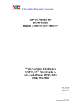
1. Tune receiver to a caption channel.
2. Check that CAPTION position is in the horizontal
center of the screen. If CAPTION center is too right or
left, perform steps 3-6. (See figure below.)
3. Select Item No. 85 [CCD] in the service mode.
4. Adjust data with + or - key for proper horizontal center.
5. Exit from the service mode.
Vertical centre
Vertical size
XXX XXXX XXXX XXX
A
B
Caption H-position Adj.
A=B
Item 02 [H-PHA] HORIZONTAL CENTRE
Item 12 [OSDHP] OSD POSITION
Horizontal centre
Item 03 [V-DC] VERTICAL CENTRE
±Item 85 [CCD] CAPTION H-POSITION ADJ.

-13-
йȉǯNjNJÎࠔÏǯǞnjțശ
JXMRR
-13-
Items 16-23 GREY SCALE
(1) Receive a monochrome circular pattern.
(2) Set the brightness and colour to normal, contrast to maximum.
(3) Enter to the service mode.
(4) Set each value of Item-16 RBIAS, 17 GBIAS, 18 BBIAS mode to 00. Set each value of Item-19 RDRIV, 21 BDRIV
mode to 63, 20 GDRIV to 07.
(5) Select Item-22 mode to be one horizontal scanning line and turn the screen volume on the FBT to obtain just vis-
ible one coloured line.
(6) Press the 1 (Red Bias +), 4 (Red Bias
-
), 2 (Green Bias +), 5 (Green Bias
-
), 3 (Blue Bias +) or 6 (Blue Bias
-
)
button to adjust the brightness of each colour until a dim white line produced. Please see the control button alloca-
tions in this mode.
(7) Select Item-23 DRV mode to enter the white balance adjusting mode.
(8) Press the 7 (Red Drive +), RECALL (Red Drive
-
), 8 (Green Drive +) or 0 (Green Drive
-
) button, 9 (Blue
Drive +) or SLEEP TIMER (Blue Drive
-
) alternately to produce normal black and white picture.
(9) Exit from the service mode.
(10) Check for proper grey scale tracking at all brightness levels.
NOTE: If the grey scale adjustment is made after picture tube replacement, check the high voltage.
Service Adjustments
Red Bias
-
Red Bias +
Green Bias
-
Blue Bias +
Red Drive +
Green Drive
-
Blue Drive +
Green Bias +
Blue Bias
-
Press the MENU button to exit from
service mode
Red Drive
-
Green Drive +
Blue Drive
-
SCREEN VR
(Under side)
MAIN BOARD

-14-
йȉǯNjNJÎࠔÏǯǞnjțശ
Service Adjustments
-14-
Service Adjustment-2 (MTS Adjustment)
1. Enter the Service Menu
While pressing the MENU button on the televi-
sion, press the Number Key 3 on the remote control
unit. The Service Menu now appear.
[ MTS Adjustment Mode ]
INPUT LEVEL 08
HI SEPARATION 21
LOW SEPARATION 34
ADJUST: - /+
CHOOSE: ▲▼
EXIT : MENU
M
E
N
U
2. Service Adjustments:
Press the CHANNEL UP or CHANNEL DOWN
button on the remote control handset to select the
desired service menu item you want to adjust.
Use the VOLUME + or
-
to adjust the data. The + or
-
button will increase or decrease the data
sequentially.
3. Exit from the Service Menu
Press the MENU button to turn off the Service Menu
display.
The data which is set in the service mode is stored
into the memory IC automatically.
MENU
[ Entering the Service Menu ]
[ Service Adjustment ]
[ Exit from the Service Menu ]
MENU
йȉǯNjNJÎࠔÏǯǞnjțശ
VOLUME +
VOLUME
-
CHANNEL UP
CHANNEL DOWN

-15-
Service Adjustments
-15-
INPUT LEVEL 08
HI SEPARATION 21
LOW SEPARATION 34
ADJUST: - /+
CHOOSE: ▲▼
EXIT : MENU
SOUND LEVEL ADJUSTMENT
1. Connect a signal to the antenna terminal with audio signal
of 1KHz at 100% modulated.
2. Connect a DC Volt-Meter to TP-317 ( pin-38 of IC3401)
and the ground.
3. Switch the TV set on, and set the Surround OFF.
Press and hold the MENU button on the TV set, and
press “3” button on the remote control transmitter to enter
to the service mode.
5. Adjust voltage to become DC 400mVrms±20mVrms at
TP317 by pressing the VOLUME(+/-) button on the remote
control or TV set.
6. To exit from the service mode, press the MENU button.
STEREO SEPARATION ADJUSTMENT
1. Connect an oscilloscope:
Probe-A to TP-317 (pin-38 of IC3401) and the ground.
Probe-B to TP-318 (pin-39 of IC3401) and the ground.
2.
Turn on the TV set, and receive the multi sound programme.
3. Press and hold the MENU button on the TV set, and press
“3” button on the remote control transmitter to enter the
service mode.
4. Select “LOW SEPARATION” by pressing the CHANNEL
UP/DOWN button on the remote control or TV set.
TP-317
(pin-38 of IC3401)
MAIN BOARD
(Solder side)
TP-318 (pin-39 of IC3401)
INPUT LEVEL 08
HI SEPARATION 21
LOW SEPARATION 34
ADJUST: - /+
CHOOSE: ▲▼
EXIT : MENU
5. Adjust the level of 300Hz at TP-317 (pin-38 of IC3401)
to become minimum level by pressing the VOLUME(+/ -)
button on the remote control or TV set.
Minimum leakage
TP-317(R)
300Hz
TP-317
(pin-38 of IC3401)
MAIN BOARD
(Solder side)
IC3401
IC3401

-16-
M
E
N
U
MENU
Service Adjustments
-16-
To return to normal TV mode, press the MENU button on
the TV set or remote control handset. (Or will automati-
cally return to normal TV mode after 5 seconds.)
FINE TUNING
-
+
Fine tuning service mode
Fine tuning data value will be automatically stored in memory.
Service Adjustment-3
FINE TUNING
This adjustment is used to do a fine tuning of the channels with poor reception after they have been stored by the
automatic tuning.
This function is available for one channel only and the fine-tuned channel is memorized into IC802 (EEPROM).
1. Enter the Service Menu
While pressing the MENU button on the television,
press the “4” or MENU button on the remote control
unit. The Service Menu now appear.
2. Service Adjustments:
Press and hold the VOLUME + or VOLUME
-
button
on the remote control handset or TV set to make fine
tuning adjustment. Press and hold the VOLUME +
button for higher frequency tuning, and press and hold
the VOLUME
-
for lower frequency tuning.
[ Entering the Service Menu ]
[ Exit from the Service Menu ]
MENU
MENU
[ Service Adjustment ]
6. Select “HI SEPARATION” by pressing the CHANNEL
UP/DOWN button on the remote control or TV set.
7. Adjust the level of 4KHz at TP-318 (pin-39 of IC3401)
to become minimum level by pressing the VOLUME (+/-)
button on the remote control or TV set.
8. To exit from the service mode, press the MENU button.
TP-318 (L)
Minimum leakage
4KHz
INPUT LEVEL 08
HI SEPARATION 21
LOW SEPARATION 34
ADJUST: - /+
CHOOSE: ▲▼
EXIT : MENU
йȉǯNjNJÎࠔÏǯǞnjțശ
VOLUME +
VOLUME
-

-17-
Service Adjustments
-17-
Service Adjustment-4
HIGH VOLTAGE CHECK
Note: +B (+130V) Voltage and Grayscale Adjustment must
be completed before attempting High Voltage Check.
1. Connect high voltage voltmeter negative lead to
ground, and connect + lead to anode of picture tube.
2. Tune receiver to an active channel and confirm TV is
operating properly.
3. The high voltage must be 25KV ± 1KV and less than
28KV at 0 beam current (Brightness and contrast
minimum setting).
Note: If the picture tube is replaced, check the high
voltage.
This TV set has a built-in power supply protection circuit.
It is provided to protect the TV set in case of a power
supply circuit malfunctions. When something abnormality
occurs during TV reception, the TV set goes to the stand-
by mode.
When an abnormality occurs during TV reception,
it causes pin 23 of the CPU to go continually Low
voltage for about one second. The CPU detects
that this has occurred and outputs the signal from
pin 36 to switch off the power supply lines.
Releasing the protective circuit and restor-
ing power supply
To release the protective circuit and restore power supply,
turn the power to the TV set OFF and then ON again via
either the main power switch or the ON-OFF button on
the remote control. This will work only if the power supply
trouble was temporary. If there is permanent trouble such
as a damaged circuit, power cannot be restored and the
circuit will have to be repaired.
Protection Circuit
FOCUS ADJUSTMENT
1. Receive the monochrome circular pattern.
2. Set the brightness to normal and contrast to maxi-
mum.
3. Adjust the focus control on the F.B.T. for the best
focus on the screen centre.
FOCUS VR (Upper side)

-18--18-
Purity and Convergence Adjustment
RED
BLUE
Adjust tabs together to
superimpose red and
blue horizontal line.
Figure- 2 BLUE AND RED LINE MOVEMENT
Figure- 3 BLUE/RED AND GREEN MOVEMENT
Adjust tabs together
to superimpose red/
blue and green hori-
zontal line.
Adjust tabs angle to superimpose
blue and red vertical line.
Adjust tabs angle to superimpose
red/blue and green vertical line.
GREEN
BLUE / RED
CAUTION: The Convergence and Purity adjustments have been made at the factory. Readjustment
should be made only after picture tube or deflection yoke replacement, following the steps below:
PURITY ADJUSTMENT
1. Demagnetize the picture tube and receiver using an external
degaussing coil. When replacing picture tube or deflection
yoke, mount deflection yoke and purity-convergence mag-
nets assembly properly, see figures 1 and 4.
2. Turn Red and Blue guns off and provide only Green raster.
Rotate Screen control to fully counterclockwise. Rotate Red
and Blue Bias controls fully counterclockwise. Slowly rotate
Green Bias control clockwise to produce Green raster.
3. Loosen the screw holding the Deflection Yoke and remove
the 3 Rubber Wedges, and slide the Deflection Yoke fully for-
ward.
4. Rotate and spread the Tabs of the two Purity Magnets to
centre the vertical green belt in the picture screen. The Purity
Magnets are also adjusted to obtain vertical centring of the
raster.
5. Slowly slide the Deflection Yoke backward until a uniform
green screen is obtained.
6. Check the purity of the red and blue screens for uniform-
ity, turn off other colours to check this (use bias controls).
Readjust the yoke position if necessary until all screens are
pure.
7. Adjust each Bias control and screen control to obtain white
raster. Refer to Gray Scale Adjustment. If part of the picture
screen is coloured, adjust the Deflection Yoke position for-
ward or backward slightly.
8. Tighten the mounting screw of the Deflection Yoke. Adjust
Convergence next.
CENTRE CONVERGENCE ADJUSTMENT
1. Use a dot crosshatch pattern signal.
2. Turn Red and Blue guns on and turn off Green gun. Adjust
the angle between the Tabs of the Four Pole Magnet 1 and 2,
and superimpose the Red and Blue vertical lines in the cen-
tre area of the picture screen. Refer to figure 2.
3. Keeping the mutual angle of the Tabs of the Four Pole
Magnet turn them together to superimpose the Blue and Red
horizontal lines in the centre area of the picture screen. Refer
to figure 2.
4. Turn Green gun on and adjust Six Pole Magnet 3 and 4 that
the Green line superimposed on the Red/Blue lines.
This is the same procedure used in steps 2 and 3.
Refer to figure 3.
OUTER AREA CONVERGENCE ADJUSTMENT
Slightly loosen the screw holding the Deflection Yoke. Adjust the
Deflection Yoke to converge the detail in the outer area (left side
and right side) of the picture screen by orbital movement of the
front of the Yoke, then secure the Deflection Yoke in appropri-
ate position by putting the wedges as illustrated. Tighten screw
holding the Deflection Yoke.
RUBBER
WEDGE
DEFLECTION YOKE
DEFLECTION YOKE
MOUNTING SCREW
Figure 4. Deflection Yoke Movement
SIX-POLE
MAGNET TABS
FOUR-POLE
MAGNET TABS
ANGLE
OF TABS
PURITY
MAGNET
TABS
4
3
2
1
FOCUS GAP
(G3-G4)
Figure 1. Purity and Convergence Magnets
MAGNET TABS
ANGLE OF MAGNET TABS
Figure 5. Adjusting Magnet
/